Fronius FK 5000 MV Operating Instructions/Spare Parts List
Cooling unit
Hide thumbs
Also See for FK 5000 MV:
- Operating instructions manual (31 pages) ,
- Operating instructions manual (60 pages)

Subscribe to Our Youtube Channel
Related Manuals for Fronius FK 5000 MV


Summary of Contents for Fronius FK 5000 MV
- Page 1 / Perfect Charging / Perfect Welding / Solar Energy Operating Instructions FK 5000, FK 5000 MV Spare parts list Cooling unit 42,0426,0079,EN 030-15032018...
- Page 3 Thank you for the trust you have placed in our company and congratulations on buying this high-quality Fronius product. These instructions will help you familiarise yourself with the product. Reading the instructions carefully will enable you to learn about the many different features it has to offer.
-
Page 5: Table Of Contents
Contents Safety rules ..............................General ..............................Proper use ............................Environmental conditions........................Obligations of the operator........................Obligations of personnel ........................Mains connection ..........................Protecting yourself and others ......................Noise emission values .......................... Danger from toxic gases and vapours ....................Danger from flying sparks ........................Risks from mains current and welding current.................. - Page 6 Symbols for care and maintenance of the cooling unit ................. Maintenance intervals, maintenance work.................... Gas purging the cooler.......................... Changing the coolant ..........................Disposal ..............................Technical data Technical data............................General ..............................FK 5000, FK 5000 MV .......................... Appendix Spare parts list: FK 5000, FK 5000 MV .....................
-
Page 7: Safety Rules
Safety rules General The device is manufactured using state-of-the-art technology and according to recognised safety standards. If used incorrectly or misused, however, it can cause: injury or death to the operator or a third party, damage to the device and other material assets belonging to the operat- ing company, inefficient operation of the device. -
Page 8: Environmental Conditions
Environmental Operation or storage of the device outside the stipulated area will be deemed conditions as not in accordance with the intended purpose. The manufacturer shall not be held liable for any damage arising from such usage. Ambient temperature range: during operation: -10 °C to + 40 °C (14 °F to 104 °F) during transport and storage: -20 °C to +55 °C (-4 °F to 131 °F) Relative humidity:... -
Page 9: Protecting Yourself And Others
Protecting your- Anyone working with the device exposes themselves to numerous risks, e.g. self and others flying sparks and hot pieces of metal Arc radiation, which can damage eyes and skin Hazardous electromagnetic fields, which can endanger the lives of those using cardiac pacemakers Risk of electrocution from mains current and welding current Greater noise pollution... -
Page 10: Danger From Toxic Gases And Vapours
Danger from toxic The fumes produced during welding contain harmful gases and vapours. gases and va- Welding fumes contain substances that may, under certain circumstances, pours cause birth defects or cancer. Keep your face away from welding fumes and gases. Fumes and hazardous gases must not be breathed in must be extracted from the working area using appropriate methods. -
Page 11: Meandering Welding Currents
During MIG/MAG welding and TIG welding, the welding wire, the wirespool, the feed rollers and all pieces of metal that are in contact with the welding wire are live. Always set the wirefeeder up on a sufficiently insulated surface or use a suit- able, insulated wirefeeder holder. -
Page 12: Emc Device Classifications
If the floor is electrically conductive, the device must be set up with sufficient insulating material to insulate it from the floor. If distribution boards, twin-head mounts, etc., are being used, note the follow- ing: The electrode of the welding torch / electrode holder that is not used is also live. -
Page 13: Emf Measures
EMF measures Electromagnetic fields may pose as yet unknown risks to health: effects on the health of others in the vicinity, e.g. wearers of pacemakers and hearing aids wearers of pacemakers must seek advice from their doctor before ap- proaching the device or any welding that is in progress for safety reasons, keep distances between the welding cables and the welder's head/torso as large as possible do not carry welding cables and hosepacks over the shoulders or wind... -
Page 14: Factors Affecting Welding Results
Use only suitable load-carrying equipment supplied by the manufacturer when transporting devices by crane. Hook chains and/or ropes onto all suspension points provided on the load-carrying equipment. Chains and ropes must be at the smallest angle possible to the vertical. Remove gas cylinder and wire-feed unit (MIG/MAG and TIG devices). -
Page 15: Danger From Escaping Shielding Gas
If the shielding gas cylinder is not connected, leave the valve cap in place on the cylinder. The manufacturer's instructions must be observed as well as applicable na- tional and international regulations for shielding gas cylinders and accesso- ries. Danger from es- Risk of suffocation from the uncontrolled escape of shielding gas caping shielding Shielding gas is colourless and odourless and, in the event of a leak, can dis-... -
Page 16: Safety Measures In Normal Operation
Safety measures Only operate the device when all safety devices are fully functional. If the safe- in normal opera- ty devices are not fully functional, there is a risk of tion injury or death to the operator or a third party damage to the device and other material assets belonging to the operator inefficient operation of the device Any safety devices that are not functioning properly must be repaired before... -
Page 17: Safety Inspection
(e.g. relevant product standards of the EN 60 974 series). Fronius International GmbH hereby declares that the device is compliant with Directive 2014/53/EU. The full text on the EU Declaration of Conformity can be found at the following address: http://www.fronius.com Devices marked with the CSA test mark satisfy the requirements of the rele- vant standards for Canada and the USA. -
Page 18: Copyright
Copyright Copyright of these operating instructions remains with the manufacturer. The text and illustrations are all technically correct at the time of printing. We reserve the right to make changes. The contents of the operating instructions shall not provide the basis for any claims whatsoever on the part of the pur- chaser. -
Page 19: General
General... -
Page 21: General
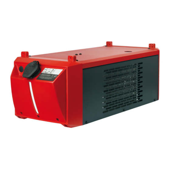
Two versions of the cooling unit are available: FK 5000 (basic version) FK 5000 MV (Multivoltage version) The FK 5000 MV adapts itself automatically to the mains voltage. The Multivoltage version is available only from the factory. Scope of supply... -
Page 22: Information About The Coolant
The symbols warn against operating the equipment incorrectly, as this may result in serious injury and damage. Part No.: www.fronius.com Ser.No.: IEC 60 974-2/-10 Cl.A IP 23 400 V 0.7 A... -
Page 23: Options
Options General The options listed below are available for all cooling unit variants. Coolant tempera- Coolant temperature monitoring and flow monitoring are parts of an installation set and ture monitoring cannot be ordered separately. and flow monitor- Coolant temperature monitoring A temperature sensor monitors the coolant return temperature during welding. -
Page 25: Connections And Mechanical Components
Connections and mechanical compo- nents... -
Page 27: Connections And Mechanical Components
Connections and mechanical components Connections and (1) (2) mechanical com- ponents Part No.: www.fronius.com Ser.No.: IEC 60 974-2/-10 Cl.A IP 23 400 V 0.7 A 50 Hz 0.42 MPa (4.2 bar) 1.0 kW 1l/min (8) (9) Front of cooling unit... -
Page 29: Installation And Commissioning
Installation and commissioning... -
Page 31: Before Installation And Commissioning
Information about The cooling unit is delivered empty. the coolant Use only original Fronius coolant (Cooling Liquid FCL 10/20 or torch coolant) when filling the cooling unit. Other coolants are not recommended for electrical conductivity and mate- rial compatibility reasons. -
Page 32: Guarantee Provisions Regarding The Coolant Pump
The manufacturer accepts no liability for damage caused in such cases. Proper use The device is intended solely for use in conjunction with Fronius system components. The device is to be used exclusively for its intended purpose. Any use above and beyond this purpose is deemed improper. The manufacturer is not lia- ble for any damage, or unexpected or incorrect results arising out of such misuse. -
Page 33: Fitting The Cooling Unit To The Trolley
Fitting the cooling unit to the trolley General The welding system can be fitted to a trolley to make the system (incl. cooling unit) more mobile. NOTE! If the welding system is not equipped with an auto-transformer, the cool- ing unit must be installed right at the bottom. Fitting the cool- *) ... -
Page 34: Connecting The Cooling Unit To The Power Source
Connecting the cooling unit to the power source Safety WARNING! An electric shock can be fatal. Before starting the work described be- low: turn the power source mains switch to the "O" position disconnect the power source from the mains ensure that the power source remains disconnected from the mains until all work has been completed After opening the device, use a suitable measuring instrument to check that elec-... -
Page 35: Connect The Coolant Hoses To The Cooling Unit
Connect the coolant hoses to the cooling unit Safety WARNING! An electric shock can be fatal. Before starting the work described be- low: turn the power source mains switch to the "O" position disconnect the power source from the mains ensure that the power source remains disconnected from the mains until all work has been completed Connecting inter-... -
Page 36: Filling And Starting Up The Cooling Unit
Filling and starting up the cooling unit Filling the cooling WARNING! An electric shock can be fatal. Before starting the work described be- unit low: turn the power source mains switch to the "O" position disconnect the power source from the mains ensure that the power source remains disconnected from the mains until all work has been completed NOTE! Make sure that no coolant enters the device. -
Page 37: Commissioning The Cooling Unit
Commissioning NOTE! Before starting up the cooling unit, first check that it contains an adequate the cooling unit amount of coolant and that the coolant is clean and uncontaminated. NOTE! During welding, check at regular intervals that the coolant is flowing prop- erly. -
Page 38: Fitting The Coolant Filter Option
Fitting the coolant filter option Safety WARNING! An electric shock can be fatal. Before starting the work described be- low: turn the power source mains switch to the "O" position disconnect the power source from the mains ensure that the power source remains disconnected from the mains until all work has been completed CAUTION! Danger of scalding by hot coolant. -
Page 39: Troubleshooting
Troubleshooting... -
Page 41: Troubleshooting
Troubleshooting Safety WARNING! Work that is carried out incorrectly can cause serious injury or dam- age. All the work described below must only be carried out by trained and quali- fied personnel. Do not carry out any of the work described below until you have fully read and understood the following documents: this document all the operating instructions for the system components, especially the safe-... - Page 42 Insufficient or no coolant flow Cause: Coolant level too low Remedy: Top up coolant Cause: Constriction or foreign body in cooling circuit Remedy: Remove constriction or foreign body Cause: Coolant contaminated Remedy: Change the coolant Cause: Coolant filter (option) misplaced when connecting coolant return Remedy: Clean coolant filter/replace filter element Cause:...
-
Page 43: Displayed Service Codes
The welding torch becomes very hot Cause: The specification of the cooling unit is inadequate Remedy: Observe the duty cycle and loading limits Cause: The specification of the welding torch is inadequate Remedy: Observe the duty cycle and loading limits Cause: Inadequate coolant flow Remedy:... -
Page 44: Twisting The Coolant Pump Shaft
Twisting the coolant pump shaft Safety WARNING! Work that is carried out incorrectly can cause serious injury or dam- age. All the work described below must only be carried out by trained and quali- fied personnel. Do not carry out any of the work described below until you have fully read and understood the following documents: this document all the operating instructions for the system components, especially the safe-... -
Page 45: Care, Maintenance And Disposal
Care, maintenance and disposal... -
Page 47: Care, Maintenance And Disposal
Care, maintenance and disposal Safety WARNING! Work that is carried out incorrectly can cause serious injury or dam- age. All the work described below must only be carried out by trained and quali- fied personnel. Do not carry out any of the work described below until you have fully read and understood the following documents: this document all the operating instructions for the system components, especially the safe-... -
Page 48: Maintenance Intervals, Maintenance Work
NOTE! If water-cooled system components are oper- ated without coolant, this will normally result in the fail- ure of the system components. Fronius shall not be liable for any damage resulting from such action. In addition, no warranty claims will be entertained. -
Page 49: Changing The Coolant
NOTE! The coolant must not be disposed of in the public sewage system. Dis- pose of coolant in accordance with the applicable local and national regulations. NOTE! Use only original Fronius coolant when refilling the cooling unit. - Page 50 NOTE! Seal off the coolant hose as soon as it is pulled out of the coolant pump connection. This will ensure that as little coolant as possible enters the device. Imme- diately remove any coolant that enters the device or spills onto its exterior.
-
Page 51: Disposal
Ensure that all hose connections are properly established and are not leaking Ensure that there is no coolant inside the device or on its exterior Disposal Dispose of in accordance with the applicable national and local regulations. -
Page 53: Technical Data
Technical data... -
Page 55: Technical Data
Flow rate Q (l/min) - The flow rate Q depends on the length of the interconnecting hosepack and the diameter of the hose. FK 5000, FK 5000 FK 5000 FK 5000 MV Mains voltage 400 V AC 200-230/400-480 V AC... -
Page 57: Appendix
Appendix... -
Page 58: Spare Parts List: Fk 5000, Fk 5000 Mv
Spare parts list: FK 5000, FK 5000 MV... - Page 60 FRONIUS INTERNATIONAL GMBH Froniusplatz 1, A-4600 Wels, Austria Tel: +43 (0)7242 241-0, Fax: +43 (0)7242 241-3940 E-Mail: sales@fronius.com www.fronius.com www.fronius.com/addresses Under http://www.fronius.com/addresses you will find all addresses of our Sales & service partners and Locations...
Need help?
Do you have a question about the FK 5000 MV and is the answer not in the manual?
Questions and answers