
Related Manuals for Lumens VC-TR1


Summary of Contents for Lumens VC-TR1
- Page 1 VC-TR1 Auto Tracking Camera User Manual - English [Important] To download the latest version of Quick Start Guide, multilingual user manual, software, or driver, etc., please visit Lumens https://www.MyLumens.com/support...
-
Page 2: Table Of Contents
6.2 Using LumensCMS Software to View the Images ..........14 6.3 Using RTSP Player to View the Images ............. 15 6.4 Get the VC-TR1 image by connecting the computer via USB ......15 Chapter 7 DIP Switch Setting ..............17 7.1 OUTPUT SWITCH .................... -
Page 3: Copyright Information
Lumens Digital Optics Inc. unless copying this file is for the purpose of backup after purchasing this product. In order to keep improving the product, Lumens Digital Optics Inc. hereby reserves the right to make changes to product specifications without prior notice. The information in this file is subject to change without prior notice. -
Page 4: Chapter 1 Safety Instructions
Chapter 1 Safety Instructions Always follow these safety instructions when setting up and using the VC-TR1 Auto Tracking Camera: 1 Operation 1.1 Please use the product in the recommended operating environment, away from water or source of heat 1.2 Do not place the product on a tilted or unstable trolley, stand or table. -
Page 5: Chapter 2 Package Contents
Chapter 2 Package Contents Instruction for VC-TR1 Remote Control installation Quick Installation Guide USB cable Power Cord Power Adapter (Type A to Type A) Appearance may vary depending on country/ region 3 PIN to 2 PIN connector (For Japan only) -
Page 6: Chapter 3 Function Introduction
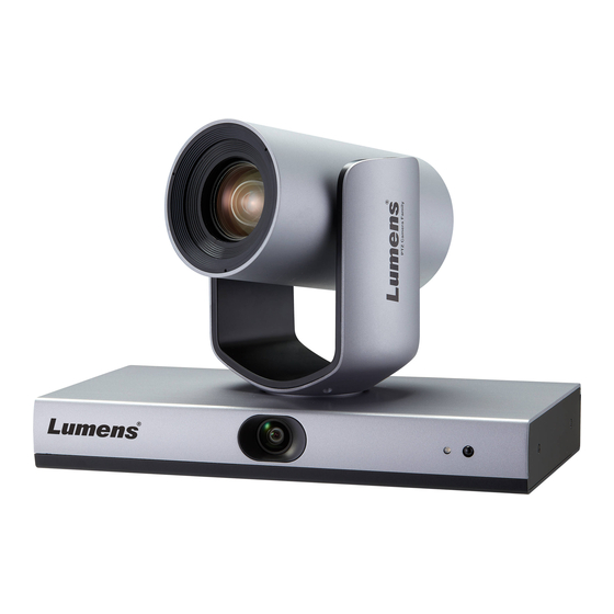
Chapter 3 Function Introduction 3.1 I/O Functions Introduction 3.1.1 Front View Item Function Descriptions Camera lens 20x HD camera lens Panoramic lens Panoramic camera lens Power indicator Display the status of the camera, please refer to 3.2 Description of LED indicator Support infrared remote control IR receive <Description>The recommended distance of IR remote control is... -
Page 7: Description Of Led Indicator
Network connecting port supports routers or hubs of PoE+ Network port (IEEE802.3at) with power supply Reserved hole Audio input Support Line In Can be used with conference software, and support up to 1080p30 USB 2.0 port <Description>USB and Ethernet cannot be used at the same time, and only one can be selected as an output port HDMI output HDMI 2.0 output (Audio output not supported) -
Page 8: Chapter 4 Instruction For Installation
Chapter 4 Instruction for installation 4.1 Scenario Applicable distance range of VC-TR1: 4-15 m, best tracking target distance recommended: Mounting height: 2 - 3 m, best height recommended: 2.4 m 4.2 Camera Size 4.2.1 Camera Front View and Side View Length x Width x Height: 245 x 145 x 165 mm Weight: 1.4 Kg (without mental plates) -
Page 9: Preparation Before Installation
4.4 Instruction for installation 4.4.1 Precautions for installation VC-TR1 does not support upside-down installation Do not grab the camera head by hand when handling the device Do not rotate the camera head by hand. Improper rotation may result in breakdown of the camera 4.4.1.1 Install the camera on the desk... -
Page 10: Connecting Devices
4.4.1.3 Install camera on the wall-mounted frame When the camera is installed on the wall, it can go with Lumens VC-WM11 wall-mounted frame (optional) 4.4.1.4 Install the camera on the ceiling bracket To install the camera on the ceiling, the ceiling bracket can be purchased separately 4.5 Connecting Devices... - Page 11 RS-232 pins definition instructions Pin NO. Definition IR OUT N.C. English - 10...
-
Page 12: Chapter 5 Remote Control And Setting Menu
Chapter 5 Remote Control and Setting Menu 5.1 Functions of remote control Item Description HOME button: PTZ returns to initial position Buttons for selecting the camera: Only working for Camera 1 Reserved buttons for Camera 2 ~ 4, no function Focus button [AUTO]: Auto focus [MANU]: Manual focus, use... -
Page 13: Setting Menu
5.2 Setting Menu <Description> Press [Menu] on the remote control to enter the setting menu; the bold underlined values in the following table are defaults. 1st Level 2nd Level 3rd Level 4th Level Adjustment Values ANTI-FLICKER OFF / 60HZ / 50HZ SHARPNESS 1~A~15 BRIGHTNESS... - Page 14 1st Level 2nd Level 3rd Level 4th Level Adjustment Values SATURATION/HUE 1~A~14 INDOOR SATURATION/HUE 1~A~14 OUTDOOR SATURATION/HUE 1~A~14 R.GAIN/ B.GAIN 0~A~128 MANUAL SATURATION/HUE 1~A~14 SODIUM LAMP SATURATION/HUE 1~A~14 FLUO LAMP SATURATION/HUE 1~A~14 CCTLEVEL 2500K~A~7500K COLOR TEMP SATURATION/HUE 1~A~14 PAN/TILT SPEED 1~A~8 PAN TILT ZOOM RATIO SPEED...
-
Page 15: Chapter 6 Network Function Settings Description
E.g.: The factory-preset default IP address of VC-TR1 is 192.168.100.100. The computer IP address must be set with the same network segment, such as 192.168.100.101, so that... -
Page 16: Using Rtsp Player To View The Images
6.4 Get the VC-TR1 image by connecting the computer via USB VC-TR1 can be connected to a PC via a USB cable as a USB video source, and used with a USB video conference system, such as AMCAP, Skype, and Zoom. - Page 17 Example: Enter Skype settings, go to audio and video page, and select VC-TR1 as the camera source English - 16...
-
Page 18: Chapter 7 Dip Switch Setting
Chapter 7 DIP Switch Setting 7.1 OUTPUT SWITCH The factory default is MENU (depend on the setting menu), and the default resolution of the setting menu is 1080p60 The camera will restart 5 seconds after modifying the DIP ... -
Page 19: Chapter 8 Troubleshooting
Chapter 8 Troubleshooting This chapter describes problems you may encounter while using VC-TR1. If you have questions, please refer to related chapters and follow all the suggested solutions. If the problem still occurred, please contact your distributor or the service center. -
Page 20: Appendix 1
Appendix 1 Output specification table IP Stream (LumensCMS setting) HDMI/SDI IP Stream Resolution Resolution 1920*1080 PTZ Main stream 1080P / 720P / D1 / QVGA 1280*720 1080P60 Panoramic stream 1080P / 720P / D1 / QVGA 640*480 Preview stream 720P / D1 / QVGA 320*240 1920*1080 PTZ Main stream... -
Page 21: Supplier's Declaration Of Conformity 47 Cfr § 2.1077 Compliance Information
Supplier's Declaration of Conformity 47 CFR § 2.1077 Compliance Information Manufacturer:Lumens Digital Optics Inc. Product Name:VC-TR1 Model Number:Auto Tracking Camera Responsible Party – U.S. Contact Information Supplier:Lumens Integration, Inc. 4116 Clipper Court, Fremont, CA 94538, United States e-mail :support@mylumens.com FCC Compliance Statement This device complies with Part 15 of the FCC Rules.
Need help?
Do you have a question about the VC-TR1 and is the answer not in the manual?
Questions and answers