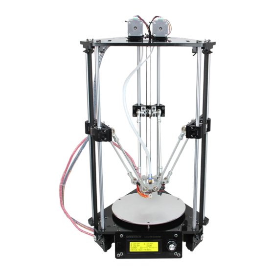
Geeetech Rostock mini G2 Quick Starter Manual
Hide thumbs
Also See for Rostock mini G2:
- Building instructions (78 pages) ,
- Building instruction (125 pages)
Advertisement
Quick Links
Geeetech Rostock mini G2 & G2s pro Quick Starter Manual
Please DO NOT rush to start your first printing after assembly, as this is a DIY kit,
some parameters of the printer may be different from each other, you need to modify
the firmware according the the real situation of your printer.
You are advised to read through the whole set-up instructions step by step to get a
whole picture of what you will be doing and stick to our instructions before you start
with your printer. Do not skip any details.
1 How to modify and upload firmware.
In the following set-up process, you will need to modify and upload the firmware by
yourself, so, first of all, let's start with the firmware compiling and uploading process.
1. Download the firmware here:
Firmware for Delta Rostock mini G2 &G2s pro
2. Connect GT2560 to your PC with a USB cable,install FTDI drive. Usually it will
install automatically. If not you need to install manually.
download the FTDI driver here.
3. If there is nothing wrong with the hardware of board, you can find COM port in
device manager. But every computer has different COM watchword, you need check
by yourself.
4. Unzip the firmware, drag all the files into Arduino IDE.(I use Arduino1.0.5),
choose Board\Arduino Mega or Mega2560, and selects ATmega2560(Mega2560) as
default Processor. The order cannot be wrong. Selects the COM port you find in the
device manager.
Advertisement

Subscribe to Our Youtube Channel
Related Manuals for Geeetech Rostock mini G2


Summary of Contents for Geeetech Rostock mini G2
- Page 1 Geeetech Rostock mini G2 & G2s pro Quick Starter Manual Please DO NOT rush to start your first printing after assembly, as this is a DIY kit, some parameters of the printer may be different from each other, you need to modify the firmware according the the real situation of your printer.
- Page 4 4 Most of the code you need to modify is in Configuration.h . More details on this later. Find the value you need to compile according to your printer. ( we will elaborate which part of setting you need to change later one by one). Upon compiling, you can upload the firmware to your control board.
- Page 5 Compiling...
- Page 6 Uploading...
- Page 7 Upload successfully 2 Printer preparing 1. Bed leveling Put a level meter on the bed when adjusting the 3 screws of the bed to check if it is level.
- Page 8 Or you can use the such a cube use a reference height about 10mm to make sure that each top of each bed mounting point is the same after tightening the wing nuts. Simply place a 10mm cube next to the bed (not under!), and tighten the screw till the cube rightly fill gap between the bed and the base plate.
- Page 9 * To protect the bed and the nozzle from crashing, please attach a piece of tape on the bed.
- Page 10 3 Printer setting Step1. Connect the USB to your Rostock mini G2 or G2s and power it up. You can see the LED lights and fan come to life, you may be able to hear the motors idling. Step 2. Open Repetier Host and ensure that you have a valid port selected for communications.
- Page 11 Step 3. Choose the Connection menu to select the COM6 port and the Baud rate 250000. Click OK to continue.
- Page 12 If you can not find the COM port, you can check the device manager to see which port it is). If you still cannot find the port, please re -install your USB driver here. Step4 set the printing speed. And un-check the disable the motors after job/kill.
- Page 13 Step5. Set the number and the offset of the extruders (offset only need for duan extruder printer),choose the nozzle size and different colors for each.
- Page 15 Step6 Choose printer shape. This is very important. Choose printer type as Rostock Printer (circular shape) and set the following parameters Home X: 0 Home Y: 0 Home Z: Max Printer Radius: 100mm Printable height: 200mm ( this is the corresponding height in the firmware, remember to modify this each time after you change the height in the firmware)
- Page 16 Step7. Write the script 1,2,3,4,5 We will use this script as shortcuts later to move the print head to the corresponding point. For each point, keep the Z as 2. For G2 or G2pro: ○ ○ ○ ○ 1 (0, 0, 2) 2 (0,50, 2) 3 (43.3, -25, 2) 4 (-43.3,-25, 2)
- Page 17 Code G2 or G2pro G2s or G2s pro Script1: G0 X0 Y0 Z2 G0 X0 Y0 Z2 Script2: G0 X0 Y50 Z2 G0 X0 Y63 Z2 Script3: G0 X43.3 Y-25 Z2 G0 X43.3 Y-2 Z2 Script4: G 0 X-43.3 Y-25 Z2 G 0 X-43.3 Y-2 Z2 Apart from the above 4 script, we need to add the fifth code to keep the print head staying in the air and will not creep down the rods.
- Page 18 Write the script 1,2,3,4,5. Here we take the G2 & G2 pro as example. Script 1: G0 X0 Y0 Z2...
- Page 20 Script 2: G0 X0 Y50 Z2...
- Page 21 Script 3: G0 X43.3 Y-25 Z2...
- Page 22 Script 4: G0 X-43.3 Y-25 Z2...
- Page 23 Script 5: G0 X0 Y0 Z180 M84 S0 Note: here we can add “M84 S0” to stop the motors from creeping down the rods when hanging in the air.
- Page 24 Step8. Remember to name the printer as delta or as you like, next time you open the Repetier Host, just choose the name of the printer, you don’t have to set the above parameters again. Step9. Hit "connect" in the upper left-hand corner. You should see the details of the connection in the console window in the bottom section of the screen.
- Page 26 4 Homing the printer Homing is the first and foremost hing you need to test. To home the printer, you can check if the three axis of the printer move in the same direction,if not, there will be crack for the spider and the carriage. Before homing, you need to follow the next steps.
- Page 27 3. Move the extruder head to the middle and be ready for emergency stop. You can click the emergency stop icon on the Repetier host or shut the power supply directly.
- Page 28 Click Homing icon, you will see the three carriages move upwards till the bolt on the carriage hit the endstop. If the three axis move in the different directions,such as one moves downwards, please check the direction setting in the firmware. E.g.
- Page 29 #define INVERT_E2_DIR false #define INVERT_E3_DIR false 5 Define the initial Z axis height If the printer can home normally, the three axis move in the same directions(Up), we can set the initial height of the Z axis now, but this value may not be the final height. ( For the G2s and G2s pro, the height is on the base of the hotend 1.)
- Page 30 1. Homing the printer and move the print head down using manual control. 2. When the Z axis reaches (0,0). You can see there is a big gap between the nozzle and the bed, about 10mm. 3. Change the height of Z axis into in the firmware.
- Page 31 #endif 2 Upon uploading, change the corresponding setting in the Repetier Host and connect.
- Page 32 Use manual control to move the Z axis down to the building platform till the nozzle just touches the bed. When moving the Z axis, please slow it down. Move 0.1mm per click.
- Page 34 5. Read the coordinates of the Z axis when the nozzle just touches the bed. E.g. if it is (0,0,4), then the Z axis height is 210-4=206。If it is (0,0,5) the height is 210-5=205. (*210 is height we just set in the firmware. 4 is the Z coordinate we read) 6.
- Page 35 6 Reconfirm the Z axis height Here, we are not measuring the height, but to adjust the printer to make the height at 205mm. That means the following adjusting is based on the the Z axis height of 205mm. Step1. Homing the printer. Step2.
- Page 36 Adjust the screw on these 3 carriages. Step3.Using G-code command to send the print head to the test points and observe the distance between the nozzle and the print surface separately for the test point 2,3,4. Click 2 on the manual control manual. The print head will move to the corresponding point.
- Page 37 When it stopped, use manual control to move the Z axis down to the building platform till the nozzle just touches the bed. When moving the Z axis, please slow it down. Move 0.1mm per click. When the nozzle just touches the bed, read the Z coordinate. If the nozzle touches the bed at the height of 2mm, but not 0 mm, you need to unscrew the bolts on the Z axis carriage.
- Page 38 Coordinate value should be the same, or almost the same. You are required to operate again and again till you get a satisfied result. Step 4. If the 3 points touch the bed at 0mm height. We can make sure that the peripheral points are in one plane.
- Page 39 Find the following code in the firmware and upload again after modifying. (For each 1.0 unit increase or reduce of the DELTA_RADIUS, the z printing volume will increase or reduce 0.2 unit) #define DELTA_RADIUS (DELTA_SMOOTH_ROD_OFFSET-DELTA_EFFECTOR_OFFSET-DELTA_CARR IAGE_OFFSET+1) You may have to adjust this for many times to keep the center point and its around point in one plane.
- Page 40 the Z axis in other words. That is 205mm as we set in the firmware. If you want to make it more accurate, you can test again refer to the steps in Define the initial Z axis height. When the height of the Z axis is determined, we have win half the battle. 7 Hotend leveling This step is exclusive for the dual extruder model.
-
Page 41: Slic3R Configuration
8 Slic3r configuration After the above setting, we can go on with the slicer setting. 1. Set the bed shape. In the latest version of Slic3r,V1.2.7, you can set the bed shape, this is very important when printing with your delta Rostock mini. go to general manual, click set button, choose circular and fill in the diameter of the printer bed. - Page 43 if your slic3r is not the latest version, you can update or download it here, unzip the file and drag them into the directory of your previous slic3r directory. do please delete the old version. Restart your Repetier and continue. 2.
- Page 44 Click OK to continue. Step 3. Save the three parameters as G2s or G2 (according to your printer and the config file you choose, here i choose G2s.)
- Page 46 2. Confirm the parameters. 1) confirm the start and end G-code. They should be like this.
- Page 47 2) confirm the extruder offset. One is 13, another is -13. For G2 and G2 pro, just set the number of the extruder as 1.
- Page 48 We have covered all the important settings. For other parameters you need to learn by yourself with the increasing of your 3D printing experience. 9 Auto-leveling function Though we have added an auto-leveling probe for the Rostock mini, but generally there is no G-code in the sli3er, so we need to add the G29 command to the sli3er.
- Page 49 Step2. Choose printer setting> Custom G-code. You can see from the start G-code, there is no G29.
- Page 50 So you need to add the G29 after G28 to start it. And change Z5 into Z50. Save the current printing setting, click “OK” to continue.
- Page 51 9.2 Check the status of endstop Before going to set up for the auto-leveling, we need to check the status of the endstops. 1. Check the wire connection. the correct connection is as follow:...
- Page 52 2. Put down the auto-level probe. And make sure the probe is not blocked by the red wires.
- Page 53 3. Homing the printer 4. Send M119 command Send the command M119 to verify the endstop first.
- Page 54 You can see the following message at the bottom of the Repetier Host. * x_max,y_max,z_max is for the endstop of the three axis: if the endstop is triggered, the feedback is Triggered; If the endstop is not triggered, the feedback is Open. *z_min is for the probe: When probe is put down, the feedback is Open;...
- Page 55 9.3 Define the Z_PROBE_OFFSET You can calculate the Z_PROBE_OFFSET values with this steps : Step1. Put down the prob. Step2. Homing the printer. Step3. Use manual control to move the print head to the building platform till the prob just touches the bed. When moving the Z axis, please slow it down to 0.1mm or 0.01mm per click.
- Page 56 9.4 Verify the auto-leveling result. Auto-leveling probe is controlled by G29 command. As this is a DIY 3d printer, you may need to help it complete the leveling: 1.You need to put down the auto-leveling probe manually.
- Page 57 2.Homing the printer.
- Page 58 3.Send G29 command. 4.Auto-leveling probe will probe the the pre-setted probing points. After probing, the print head will raise up a bit and stop in the air.
- Page 59 5.Hook up the probe manually.
- Page 60 3.Send G1 X0 Y0 command to move the printing head to the center (0,0). 4.Click -Z icon on manual control to move the print head down until it rightly touches the print bed.
- Page 61 5. Send M114 command to get the present coordinates.
- Page 62 6. If the coordinate is (0,0,0), the auto-leveling is successful.
- Page 63 7.If not, you need to modify the #define Z_PROBE_OFFSET_FROM_EXTRUDER -0.9 , e.g. Reduce -0.9 to -1.1, and then re-upload the firmware and test again. 8.You may have to test it for more than once, but for the sake of better printing object,please be patient.
-
Page 64: Printing Test
9.5 Overall steps for the auto-leveling calibration 1.Manually put down the probe, then send M119 command to check if the Z-min is open. 2.Send G28 command to auto home the printer. 3.Send G29 command to start the auto-leveling. *there might be collisions, please always be ready to cut off the power supply. - Page 65 1. Load the filament into the pipe from the push-fitting on the extruder. 2. Download this stl.file to test printing. And unzip it. 3. Click printing setting> extruder, change the number of extruder to 1.
- Page 66 3.Open slis3r> configuration 4.Click file>Load the config.file you download before.
- Page 67 5. Save the three parameters as G2 (or anything you like).
- Page 68 1.Note the nozzle size below, set it according to your printer, the default kit is 0.4mm. 2. The Extruder offset is x:0, y:0 mm...
- Page 69 6. Confirm the start and end G-code. They should be like this. We have covered all the important settings. For other parameters you need to learn by yourself with the increasing of your 3D printing experience. Choose the printer and printing settings, filament settings we just saved in the drop-down menu.
- Page 70 ○ 8. Load the stl. File you will print from Object placement > + icon. Direct to the file and open it. 9. Stl. File is successfully loaded.
- Page 71 9. You can see it in the preview window. And you can choose different point of view by clicking the cubic on the left.
- Page 72 11. Click Slic3r> slice with Slic3r.
- Page 73 12 After slicing, you will get the following information about this printing job.
- Page 74 13 click G-code Editor to save the file for future use. Or if you have SD card, you can click SD card to save it in the SD card. 14. Click manual control and remove the slash on fan, heated bed and extruder 1.(If you are using extruder 1 now)
- Page 75 14. Click start print job to begin. 15. When the temperature reaches the preset value, the printer will start printing, you will see the operation track of the print head as shown below.
- Page 76 If you want to stop the printing job, just click pause. Now you can take a rest and wait till the model is built. Example 2. Print with dual extruder. 1. Download the stl. File here and unzip. 2. Click printing setting> extruder, change the number of extruder to 2.
- Page 77 3. Choose the printer and printing settings, filament settings we just saved in the drop-down menu. Here we choose G2s.
- Page 78 ○ 10. Load the stl. File you will print from Object placement > icon. Direct to the file and open it. Load both files. 9. Stl. File is successfully loaded.
- Page 79 Now, you can see the two files are separated. You need to put them together.
- Page 80 You need to put them together. Choose the file and click center icon on the top separately. Now the two files are centered and combined together.
- Page 81 10.Assign extruder for each file. 11. Click Slic3r> slice with Slic3r. Choose No to continue.
- Page 82 12 After slicing, you will get the following information about this printing job.
- Page 83 13 click G-code Editor to save the file for future use. Or if you have SD card, you can click SD card to save it in the SD card.
- Page 84 14. Click manual control and remove the slash on fan, heated bed and extruder 1.(If you are using extruder 1 now) 16. Click start print job to begin. 17. The printer will home first and wait till the temperature reaches the preset value, the printer will start printing, you will see the operation track of the print head as shown below.
- Page 85 The printer is working now. That is all for the geeetech rostock mini G2 and G2s pro. If you have any problem running the printer, please go to our forum for tech support.
Need help?
Do you have a question about the Rostock mini G2 and is the answer not in the manual?
Questions and answers