Table of Contents

Related Manuals for CKD FFLD Series


Summary of Contents for CKD FFLD Series
- Page 1 Electric Actuator FFLD Series INSTRUCTION MANUAL SM-A25107/3-A • Read this Instruction Manual before using the product. • Read the safety notes carefully. • Keep this Instruction Manual in a safe and convenient place for future reference.
-
Page 2: Preface
• Since there are a wide variety of customer applications, it is impossible for CKD to be aware of all of them. Depending on the application and usage, the product may not be able to exercise its full performance due to fluid, piping, and other conditions, or an accident may occur. -
Page 3: Safety Information
SM-A25107/3-A SAFETY INFORMATION SAFETY INFORMATION When designing and manufacturing any device incorporating the product, the manufacturer has an obligation to ensure that the device is safe. To that end, make sure that the safety of the machine mechanism of the device and the electric system that controls such mechanism is ensured. In order to use our products safely, it is important to select, use, handle, and maintain the products properly. -
Page 4: Precautions On Product Use
SM-A25107/3-A SAFETY INFORMATION Precautions on Product Use DANGER Do not use the product for the following applications: • Medical equipment pertaining to sustainment and management of human life and body • Mechanism and mechanical device for transferring and transporting people •... -
Page 5: Table Of Contents
Names of Parts ....................2 1.3.1 FFLD-08,30 ....................2 1.3.2 FFLD-50 ....................... 3 Model Number Indication ..................4 1.4.1 FFLD Series ....................4 Specifications ...................... 5 1.5.1 Actuator specifications ................. 5 1.5.2 Communication specifications ..............6 INSTALLATION ......................7 Environment .......................11 Unpacking ......................11... - Page 6 SM-A25107/3-A CONTENTS 3.7.8 Positioning width ..................60 Manual Operation ..................... 61 3.8.1 FFLD-08,30 ....................61 3.8.2 FFLD-50 ..................... 62 MAINTENANCE AND INSPECTION ............... 63 Periodic Inspection.................... 64 4.1.1 Inspection item ................... 64 TROUBLESHOOTING..................... 65 Items to Check When a Problem Occurs ............65 Alarm Code .......................
-
Page 7: Product Overview
SM-A25107/3-A 1. PRODUCT OVERVIEW 1. PRODUCT OVERVIEW 1.1 System Overview 1.1.1 System structure Components in the system structure that are available from CKD are listed below. Component Product name/Model no. This product Actuator/Controller FFLD Series 24 VDC power supply EA-PWR-KHNA240F-24... -
Page 8: Instruction Manuals Related To This Product
SM-A25107/3-A 1. PRODUCT OVERVIEW 1.2 Instruction Manuals Related to This Product For the Instruction Manuals for controllers and setting tools related to this product, refer to the following. Part name PC Setting Software for Electric Actuators - S-Tools SM-A11147 1.3 Names of Parts 1.3.1 FFLD-08,30 ◼... -
Page 9: Ffld-50
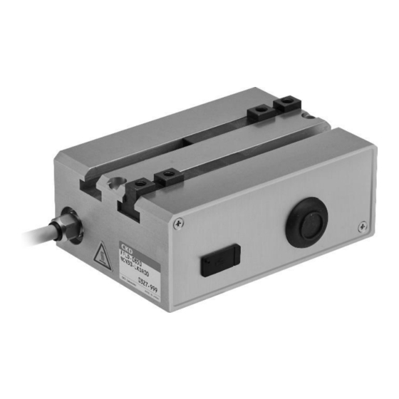
SM-A25107/3-A 1. PRODUCT OVERVIEW 1.3.2 FFLD-50 ◼ External appearance USB cover Manual operation cover Actuator Finger Lead cable Threaded hole for earthing Controller (built into the actuator) ◼ Connection Manual operation shaft CN2: USB connector CN1: Interface connector Symbol Part name Description Connector for connecting to upper level equipment Refer to "2.4.1 Connecting to upper level equipment"... -
Page 10: Model Number Indication
SM-A25107/3-A 1. PRODUCT OVERVIEW 1.4 Model Number Indication 1.4.1 FFLD Series 2021-03-23... -
Page 11: Specifications
SM-A25107/3-A 1. PRODUCT OVERVIEW 1.5 Specifications 1.5.1 Actuator specifications Model FFLD-08 FFLD-30 FFLD-50 Item □20 □25L □25L Motor size Motor type Stepping motor Encoder type Incremental encoder Drive system Rack and pinion, worm gear Controller Embedded Stroke (mm) 100 (50 per finger) 140 (70 per finger) 160 (80 per finger) Gripping power (each finger) -
Page 12: Communication Specifications
Note 1: When setting the data with the IO-Link master (PLC), if the data table cannot be set with the data length shown here, the data table is generally mapped to be larger than this data length. Note 2: Indicates CKD Corporation. Note 3: Indicates this product. -
Page 13: Installation
SM-A25107/3-A 2. INSTALLATION 2. INSTALLATION DANGER Do not use the product in a place where dangerous substances such as ignitable, inflammable, or explosive materials are present. Ignition, inflammation, or explosion may occur. Prevent water and oil from splashing onto the product. A fire, electric leakage, or failure may occur. - Page 14 SM-A25107/3-A 2. INSTALLATION WARNING Do not install the product to a combustible material. If the product is installed directly to or near a combustible material, a fire may result. If the system is such that the machine stops in the event of a system failure such as an emergency stop or a power failure, design and implement a safety circuit or a safety device to prevent damages to the devices and injuries to people.
- Page 15 SM-A25107/3-A 2. INSTALLATION CAUTION Install the wiring so that no induction noise is applied. • Avoid using the product in a place where a large current or strong magnetic field occurs. • Do not pipe or wire the product in the same wiring (with multi-conductor cables) as the power lines for other large motors.
- Page 16 SM-A25107/3-A 2. INSTALLATION CAUTION Do not carry or install the product by holding its cable or the movable section. An injury or cable disconnection may occur. Secure sufficient space for maintenance and inspection. Maintenance and inspection cannot be performed if sufficient space is not provided and this may cause equipment stoppage, failure, or injury.
-
Page 17: Environment
SM-A25107/3-A 2. INSTALLATION 2.1 Environment • Check the environment temperature and atmosphere before using and storing the product. • Use the product at an ambient temperature between 0°C and 40°C. Ventilate if heat can become trapped. • Use the product at an ambient humidity between 35% and 80%. Do not use the product in a place where condensation occurs. -
Page 18: Mounting
SM-A25107/3-A 2. INSTALLATION 2.3 Mounting 2.3.1 Body Do not apply an excessive shock or moment to the slider. • A malfunction or damage may occur. The flatness of the workpiece mounting surface should be 0.02 mm or less. Do not apply •... -
Page 19: Fingers
SM-A25107/3-A 2. INSTALLATION 2.3.2 Fingers When tightening the bolts to mount the attachment to the finger, support the finger using a tool such as a spanner so to prevent the finger from distorting and having an effect on the actuator body. -
Page 20: Wiring
SM-A25107/3-A 2. INSTALLATION 2.4 Wiring WARNING Turn off the power before wiring. An electric shock may occur by touching the electrical wiring connection (bare live part). Do not touch live parts with bare hands. An electric shock may occur. Thoroughly read and understand this Instruction Manual before working on electrical wiring. CAUTION Check the working voltage and polarity before wiring and energizing. - Page 21 SM-A25107/3-A 2. INSTALLATION ◼ Connection method <IO-Link master, power supply> Wire the master and the power supply according to the connection diagram below <Network cable> Follow the steps below to connect the network cable to CN1. After confirming safety, stop network communication and turn off all peripheral equipment. Refer to the following figure to wire the IO-Link compliant network cable (M12 connector, 5-conductor) to the network connector included.
- Page 22 SM-A25107/3-A 2. INSTALLATION <Y-branch connector> Follow the steps below to use a Y-branch connector (sold separately) for wiring to CN1. After confirming safety, stop network communication and turn off all peripheral equipment. Wire the Y-branch connector to CN1. Refer to the following figure to wire the IO-Link compliant network cable (M12 connector, 4-conductor) to Y-branch connector.
-
Page 23: Connecting To S-Tools
SM-A25107/3-A 2. INSTALLATION 2.4.2 Connecting to S-Tools CAUTION During normal operation, remove the USB cable from the controller before use. The actuator may malfunction. ◼ Communication specifications Item Specification Interface USB 2.0 Baud rate Full speed (12 Mbps) ◼ Connection method(FFLD-08,30) <Connecting>... - Page 24 SM-A25107/3-A 2. INSTALLATION ◼ Connection method(FFLD-50) <Connecting> Follow the steps below to connect the PC. Remove the bolts and attach it to screw hole. Pull on the bolts and remove the USB cover. Connect a USB cable (mini-B) to CN2 and PC's USB port. <Disconnecting>...
-
Page 25: Usage
SM-A25107/3-A 3. USAGE 3. USAGE 3.1 Safety Instructions DANGER Do not enter the operating area of the device when the product is in an operational state. The product may operate unexpectedly and an injury may occur. Do not work with wet hands. An electric shock may occur. - Page 26 SM-A25107/3-A 3. USAGE CAUTION Do not move the movable section of the product with external force and do not use the product in an application that requires the movable section to decelerate suddenly. A malfunction or damage may occur due to regenerative currents. Other than in home position return and pressing operations, do not subject the fingers to impact (such as allowing the fingers to hit against the stroke end or the attachments to collide with each other).
-
Page 27: Iodd File
IODD file. Use the latest IODD file to configure an appropriate network. The IODD file is available on our company’s website (https://www.ckd.co.jp/). Other files are downloaded at the same time as the IODD file. Copy them to the folder designated by the PLC development tool used. -
Page 28: Communication Format
SM-A25107/3-A 3. USAGE 3.4 Communication Format Process data and service data are transmitted and received between the PLC and the controller. 3.4.1 Process data The controller is operated from the PLC by operating the items described later with process data. In addition, the present position can be monitored. - Page 29 SM-A25107/3-A 3. USAGE ◼ Process data input (FFLD IO-Link master) Item Format Unit Byte order Status monitor UInteger8 Point number monitor UInteger8 Present position monitor Integer16 0.01 mm 2, 3 Selection monitor UInteger8 % mm/s <Byte 0: Status monitor> Description Item Setting...
- Page 30 SM-A25107/3-A 3. USAGE <Byte 1: Point number monitor> Description Item Setting This item is ON ("1") when the actuator has started direct 0: Point travel value travel and OFF ("0") when the actuator has started Direct value travel status 1: Direct value travel point travel.
- Page 31 SM-A25107/3-A 3. USAGE <Byte 0: Control 1> Description Item Setting When this item is ON ("1"), the actuator can travel. When it is OFF ("0"), the actuator cannot travel. 0: Stop When it is set to OFF while the actuator is traveling, the Stop 1: Release actuator decelerates to a stop and the travel command is...
- Page 32 SM-A25107/3-A 3. USAGE <Byte 1: Point number selection> Description Item Setting Point number selection bit 5 Point number selection bit 4 Point number selection bit 3 When set to direct value travel, this bit is not referenced. 0 to 63 When set to point travel, the point number can be set.
- Page 33 SM-A25107/3-A 3. USAGE <Byte 9: Mode selection (direct value travel)> Item Setting 0: Absolute Position specification method 1: Incremental 0: Positioning operation Operation method 1: Pressing operation 1 2: Pressing operation 2 0: Common 1: Control 2: Fixed excitation Stop method 3: Automatic servo OFF 1 4: Automatic servo OFF 2 5: Automatic servo OFF 3...
- Page 34 SM-A25107/3-A 3. USAGE <Byte 14: Control 2> Description Item Setting INCH is selected when this item is ON ("1") and the actuator will start inching with "JOG/INCH (+)/(−) travel 0: JOG start". INCH selection 1: INCH JOG is selected when this item is OFF ("0") and the actuator will start jogging with "JOG/INCH (+)/(−) travel start".
- Page 35 SM-A25107/3-A 3. USAGE ◼ Timing charts The minimum communication cycle time of this product is 10 ms. Response output may be delayed depending on the cycle time. <From power-on to home position return> CAUTION Make sure that the fingers are not in contact with the mechanical end or the workpiece before the first servo ON after power-on.
- Page 36 SM-A25107/3-A 3. USAGE <Positioning operation: Point number selection> Set the point number to which the actuator should travel to Point number selection. Set Travel start to ON. When the actuator completes traveling, Travel complete switches to ON and the point number is output to Point number confirmation.
- Page 37 SM-A25107/3-A 3. USAGE <Positioning operation: direct value travel selection> Set the point data for direct value travel in process data output. Set Direct value travel selection to ON. (Order of steps 1 and 2 can be reversed.) Set Travel start to ON. When the actuator completes traveling, Travel complete switches to ON.
- Page 38 SM-A25107/3-A 3. USAGE <Jog/Inch operation> Jog operation Set JOG/INCH speed in service data as desired. Set INCH selection to OFF. To operate the actuator in the direction in which the fingers close, set JOG/INCH (+) travel start to ON. To operate the actuator in the direction in which the fingers close, set JOG/INCH (−) travel start to ON.
- Page 39 SM-A25107/3-A 3. USAGE <Alarm> When an alarm is triggered, the servo is turned off and Operation preparation complete switches to OFF. When the alarm is cleared with Alarm reset, the servo is turned back on and Operation preparation complete also switches back to its original state. Some alarms cannot be reset.
-
Page 40: Service Data
SM-A25107/3-A 3. USAGE 3.4.2 Service data With service data (on-request data, message communication), the point data and parameters are set, and the alarm history is read. The controller is operated from the PLC by transmitting and receiving service data. Also, process data can be read as service data. Process data input Index: 0x0028 Process data output... - Page 41 SM-A25107/3-A 3. USAGE ◼ Access example 3: Transmitting a message to the controller from the IO-Link master The following object format provides only the information necessary for explaining the data writing and reading examples described later. Since the format differs depending on the object used, refer to the manual for the IO-Link master for details on the object.
- Page 42 SM-A25107/3-A 3. USAGE If the entire data composed of multiple elements (data with multiple Subindex data) is • accessed with Subindex = 0, some items (such as the point data "Position specification method") will have bit configuration. Refer to "3.4 Communication Format" for details. If the data of the item that is stored with the DS function is rewritten, data download in the DS •...
- Page 43 In each table, "R" stands for Read and "R/W" stands for Read/Write. (1) Identification Index Value Data Item Access Format (Hex) index (Dec) length 0x0010 Vendor Name CKD Corporation 64 bytes String 0x0011 Vender Text https://www.ckd.co.jp/ 64 bytes String 0x0012 Product Name FFLD-LK 64 bytes String 0x0013...
- Page 44 SM-A25107/3-A 3. USAGE (2) Parameters and commands Common specifications Index Value Data Item Access Format Note (Hex) index (Dec) length 0x0002 System Command Refer to the table "System Command". 1 byte UInteger8 0x0000: Unlocked 0x000C Device Access Locks 0x0001: Parameter locked 2 bytes Record ●...
- Page 45 SM-A25107/3-A 3. USAGE Individual specifications 1 (Vendor) Index Value Data Item Access Format (Hex) index (Dec) length 0x0042 Data Storage mode 1: Forced upload Note 1 1 byte UInteger8 1: Data initialization executing 0x0044 Data initialization executing 1 byte UInteger8 Note 2 Note 1: This requests a forced data storage upload.
- Page 46 SM-A25107/3-A 3. USAGE Individual specifications 3 Index Value Data Item Access Format Note (Hex) index (Dec) length Soft limit + 0x0302 Soft limit (−) to + stroke 2 bytes Integer16 ● (0.01 mm) Soft limit − 0x0304 − stroke to soft limit (+) 2 bytes Integer16 ●...
- Page 47 SM-A25107/3-A 3. USAGE Individual specifications 5 Index Value Data Item Access Format Note (Hex) index (Dec) length Common positioning width 0x0319 1 to 999 2 bytes UInteger16 ● (0.01 mm) Common speed 0x031A 1 to 10 1 byte UInteger8 ● (mm/s) Common acceleration 0x031B...
- Page 48 SM-A25107/3-A 3. USAGE Individual specifications 6 Index Value Data Item Access Format (Hex) index (Dec) length 0x0400 Actuator mode number FFLD-****NCN30-LK 40 bytes String 0x0401 Actuator serial number ****-*** 16 bytes String Integrated number of travels 0x0451 0 to 999999999 4 bytes UInteger32 (times)
- Page 49 SM-A25107/3-A 3. USAGE Process data input Index Value Data Item Access Format (Hex) index (Dec) length All items Process data input 5 bytes Record (Read in the following order) 0: Incomplete Operation preparation 1 byte UInteger8 1: Complete complete 0: Triggered 1 byte UInteger8 Warning...
- Page 50 SM-A25107/3-A 3. USAGE Process data output Index Value Data Item Access Format (Hex) index (Dec) length All items Process data output 15 bytes Record (Read in the following order) 0: Stop 1 byte UInteger8 Stop 1: Release Alarm reset 1: Reset 1 byte UInteger8 0: Servo OFF...
- Page 51 SM-A25107/3-A 3. USAGE ◼ Return error When reading/writing data, following error codes are set as FB output parameters for the set input parameters. If CoE object is used, the error codes are set to Subindex = 0x07 (Errorcode) of the corresponding Index (such as 0x4000).
-
Page 52: Data Storage (Ds) Function
SM-A25107/3-A 3. USAGE 3.5 Data Storage (DS) Function Data Storage function is a function that backs up the IO-Link device setting parameter data for each port of the IO-Link master. With this function, the backup data can be restored as necessary, such as when the IO-Link device is replaced due to a failure. -
Page 53: Download/Upload
SM-A25107/3-A 3. USAGE 3.5.2 Download/Upload ◼ Download If the backup data stored in the IO-Link master does not match the parameter data set in the connected IO-Link device at startup, the IO-Link master downloads the stored backup data. Therefore, if the controller is replaced with a backup controller for reasons such as a controller failure, the minimum setting data required for operation can be written to the new controller. - Page 54 SM-A25107/3-A 3. USAGE ◼ Items that can be uploaded/downloaded Item Data length Device Access Locks 2 bytes Application Specific Tag 32 bytes Soft limit (+) 2 bytes Soft limit (−) 2 bytes Home position return speed 1 byte Home position offset amount 2 bytes Home position return direction 1 byte...
-
Page 55: Parameters
SM-A25107/3-A 3. USAGE 3.6 Parameters Parameter settings and changes are executed by accessing service data. Settings and changes can also be executed with the setting software (S-Tools). Refer to the Instruction Manual for S-Tools (SM-A11147) for details. 3.6.1 List of parameters Name Initial Description... - Page 56 SM-A25107/3-A 3. USAGE Initial Name Description Setting range Unit value This is for setting the point zone automatic setting during pressing operation to "Enabled" or "Disabled". Automatic point zone If the point data "Point zone (+)/(−)" is set, the point Enabled, Disabled Disabled None...
-
Page 57: Soft Limits
SM-A25107/3-A 3. USAGE 3.6.2 Soft limits The movable range can be set for the transfer operation and the pressing operation. If the range of the soft limit is exceeded during those operations, an alarm is output. If the operation completion position is outside the range of the soft limit, an alarm is output at the start of the operation. -
Page 58: Home Position Return Operation
SM-A25107/3-A 3. USAGE 3.6.3 Home position return operation If the home position return direction is "normal", the home position return is performed by pressing against the mechanical end of the finger opening direction. If the home position return direction is "opposite", the home position return is performed by pressing against the mechanical end of the finger closing direction. -
Page 59: Automatic Point Zone
SM-A25107/3-A 3. USAGE 3.6.4 Automatic point zone For the pressing operation, a point zone can be set at the position of "pressing start point" + "automatic point zone position" with respect to the traveling direction. The offset position from the pressing start point is set to "automatic point zone position". When this setting is "Enabled", it is valid for all pressing operations. -
Page 60: Point Data
SM-A25107/3-A 3. USAGE 3.7 Point Data Point data settings and changes are executed by accessing service data. Settings and changes can also be executed with the setting software (S-Tools). Refer to the Instruction Manual for S-Tools (SM-A11147) for details. 3.7.1 Number of point data The number of point data that can be set for the actuator is 64 points. -
Page 61: Position Specification Method
SM-A25107/3-A 3. USAGE 3.7.3 Position specification method Absolute or incremental can be selected for the position specification method. Position Description Setting example specification Example) Point 1 position: +30 mm is set Home Point 1 Opposite the motor Distance from the home Motor position is set using the Absolute... - Page 62 SM-A25107/3-A 3. USAGE <Pressing operation 1> 横軸:時間 Horizontal axis: Time Pressing operation 押付け動作 Start position 開始位置 変位 Displacement Operation 動作開始位置 Start position 搬送時の Set transfer speed 設定速度 Speed 速度 Pressing speed 押付け速度 Pressing current 押付け電流 Current 電流 Automatic servo OFF time 自動サーボOFF時間...
- Page 63 SM-A25107/3-A 3. USAGE <Pressing operation 2> Horizontal axis: Time 横軸:時間 押付け動作 Pressing operation Complete position 完了位置 Pressing operation 押付け動作 Start position 開始位置 変位 Displacement Operation 動作開始位置 Start position 搬送時の Set transfer speed 設定速度 Speed 速度 Pressing speed 押付け速度 Holding current at stop 停止時固定電流...
-
Page 64: Position
SM-A25107/3-A 3. USAGE 3.7.5 Position Position of point operation is set. The implications change depending on the operation method. Operation Setting example Example Set to Point 1 Position (absolute): +50 mm Present position Point 1 Final target position Speed Positioning operation Distance 50 mm Set position is the final target position. -
Page 65: Stop Method
SM-A25107/3-A 3. USAGE 3.7.6 Stop method The stop method applied upon completion of the positioning operation and pressing operation (pressing operation 2) is set. Either Common, Control, Fixed excitation, or Automatic servo OFF 1 to 3 can be selected for the stop method. -
Page 66: Positioning Width
SM-A25107/3-A 3. USAGE 3.7.8 Positioning width The output range of Travel complete output signal is set. It is the width (per finger) (mm) with respect to the operation completion position. The positioning width can only be changed by the common setting. Operation Setting example Example... -
Page 67: Manual Operation
SM-A25107/3-A 3. USAGE 3.8 Manual Operation CAUTION Before performing manual operation, make sure that the servo is turned off. The product may become damaged or malfunction. Do not apply any excess force to the manual operation shaft. A damage or operation fault may occur. Manual operation is mainly intended for use during startup, maintenance, and inspection. -
Page 68: Ffld-50
SM-A25107/3-A 3. USAGE 3.8.2 FFLD-50 ◼ Operation Remove the manual operation cover and turn the manual operation shaft with a flat blade screwdriver. Manual operation shaft dimensions Manual operation shaft Remove manual operation cover ◼ Direction of operation and rotation CW: The fingers close. -
Page 69: Maintenance And Inspection
SM-A25107/3-A 4. MAINTENANCE AND INSPECTION 4. MAINTENANCE AND INSPECTION WARNING Install the product before wiring. An electric shock may occur. Do not work with wet hands. An electric shock may occur. Before performing wiring and inspection, wait five minutes or longer after turning off the power and check the voltage with a tester. -
Page 70: Periodic Inspection
SM-A25107/3-A 4. MAINTENANCE AND INSPECTION 4.1 Periodic Inspection In order to use the product under optimum conditions, perform a periodic inspection two to three times a year. 4.1.1 Inspection item Turn off the power before performing items 1, 2, and 3 below. Inspection item Inspection method Action... -
Page 71: Troubleshooting
SM-A25107/3-A 5. TROUBLESHOOTING 5. TROUBLESHOOTING 5.1 Items to Check When a Problem Occurs When a problem occurs, ensure safety and follow the procedure below. Check if there is a problem with the PLC. Check the voltage of L+ (24 VDC) of the communication cable. Check the details on the alarm. -
Page 72: Alarm Code
Initialize the alarm data and power cycle. Other codes indicate that there is an error in the data inside. If the error reoccurs even after power cycling, contact your nearest CKD sales office or distributor. An error has been 0x2000... - Page 73 Check that there is no problem and reset the alarm. output has continued. 0x6BFF An error has been 0x7000 Memory detected in initializing If the error reoccurs even after power cycling, contact your nearest (Initialization) memory data when CKD sales office or distributor. 0x7FFF changing data. 2021-03-23...
- Page 74 SM-A25107/3-A 5. TROUBLESHOOTING ◼ Warnings A warning is output when a slight error that does not affect the operation of the actuator is detected. It can be cleared by changing the controller settings. Alarm Alarm item Problem Cause/Solution code The integrated number of travels has exceeded the threshold set in The integrated number Maintenance the user parameter.
-
Page 75: Problems, Causes, And Solutions
Check how long the product has been in use (operation distance). Repair or replace the product. Actuator body is damaged. Refer to "5.1 Items to Check When a Problem Occurs" and contact your nearest CKD sales office or distributor. Product itself vibrates. Connection to actuator is loose. Tighten the bolts. - Page 76 Check that the workpiece weight and the operation speed satisfy the Amount of deceleration is large Overshoot occurs. specified values. because transfer weight is large. Adjust the gain. If you have any other questions or concerns, contact your nearest CKD sales office or distributor. 2021-03-23...
-
Page 77: Product Compliance
This product is intended to be incorporated into the customer equipment and use as a part of equipment. The CE marking affixed to the product itself indicates that CKD has declared conformity to the EMC Directive under our limited conditions. If the customer equipment incorporating this product is to be shipped to or used in the European Economic Area as a final product, it is the responsibility of the customer to confirm compliance with the EU Directives. -
Page 78: System Structure
6.1.2 System structure The following figure shows an example of how the system should be structured when using this product (FFLD Series) as a product conforming to the European standards. A surge protector is required to comply with European standards. -
Page 79: Warranty Provisions
If the product specified herein fails for reasons attributable to CKD within the warranty period specified below, CKD will promptly provide a replacement for the faulty product or a part thereof or repair the faulty product at one of CKD’s facilities free of charge.
Need help?
Do you have a question about the FFLD Series and is the answer not in the manual?
Questions and answers