Juniper CTP2000 Series Hardware Documentation
Hide thumbs
Also See for CTP2000 Series:
- Hardware manual (149 pages) ,
- Quick start manual (27 pages) ,
- Upgrade (26 pages)

Related Manuals for Juniper CTP2000 Series


Summary of Contents for Juniper CTP2000 Series
- Page 1 CTP2000 Hardware Documentation Modified: 2017-03-01 Copyright © 2017, Juniper Networks, Inc.
- Page 2 END USER LICENSE AGREEMENT The Juniper Networks product that is the subject of this technical documentation consists of (or is intended for use with) Juniper Networks software. Use of such software is subject to the terms and conditions of the End User License Agreement (“EULA”) posted at http://www.juniper.net/support/eula.html.
-
Page 3: Table Of Contents
Chapter 1 CTP2000 Series Platform Overview ........3 Introducing CTP Platforms . - Page 4 CTP2000 Serial Interface Module Pinouts ....... 49 CTP2000 Series Console Cable Pinouts ....... . 58 CTP Fast Ethernet and Power Cables .
- Page 5 Contacting Juniper Networks ........
- Page 6 Information You Might Need to Supply to JTAC ......134 Copyright © 2017, Juniper Networks, Inc.
- Page 7 Chapter 1 CTP2000 Series Platform Overview ........3 Figure 1: PP833 Processor (AC and DC Version, Front View) .
- Page 8 Figure 28: CTP2000 Serial DCE/DTE Cable Pin Configurations ....49 Figure 29: CTP2000 Series Console Cable Pin Configurations for PP310 and PP332 Processors ..........59 Figure 30: Upgrading from PP310/PP332 Processor to PP833 Processor .
- Page 9 Chapter 2 CTP2000 Series Interface Modules ........11 Table 3: Jumper Positions for Configuring Port Signaling Type .
- Page 10 Table 25: Required Cables ......... . . 102 Table 26: CTP Power Supply Cables and Wires Needed ....104 Copyright © 2017, Juniper Networks, Inc.
-
Page 11: About The Documentation
® To obtain the most current version of all Juniper Networks technical documentation, see the product documentation page on the Juniper Networks website at http://www.juniper.net/techpubs/ If the information in the latest release notes differs from the information in the documentation, follow the product Release Notes. -
Page 12: Table 1: Notice Icons
RFC 1997, BGP Communities Attribute Italic text like this Represents variables (options for which Configure the machine’s domain name: you substitute a value) in commands or [edit] configuration statements. root@# set system domain-name domain-name Copyright © 2017, Juniper Networks, Inc. -
Page 13: Documentation Feedback
We encourage you to provide feedback, comments, and suggestions so that we can improve the documentation. You can provide feedback by using either of the following methods: Online feedback rating system—On any page of the Juniper Networks TechLibrary site , simply click the stars to rate the content, http://www.juniper.net/techpubs/index.html and use the pop-up form to provide us with information about your experience. -
Page 14: Requesting Technical Support
7 days a week, 365 days a year. Self-Help Online Tools and Resources For quick and easy problem resolution, Juniper Networks has designed an online self-service portal called the Customer Support Center (CSC) that provides you with the following features: Find CSC offerings: http://www.juniper.net/customers/support/... - Page 15 About the Documentation For international or direct-dial options in countries without toll-free numbers, see http://www.juniper.net/support/requesting-support.html Copyright © 2017, Juniper Networks, Inc.
- Page 16 CTP2000 Hardware Documentation Copyright © 2017, Juniper Networks, Inc.
-
Page 17: Overview
PART 1 Overview CTP2000 Series Platform Overview on page 3 CTP2000 Series Interface Modules on page 11 Copyright © 2017, Juniper Networks, Inc. - Page 18 CTP2000 Hardware Documentation Copyright © 2017, Juniper Networks, Inc.
-
Page 19: Ctp2000 Series Platform Overview
Web-based management tool for provisioning, managing, running diagnostics, monitoring, and reporting on all CTP devices and circuits in the network. CTP2000 Series Processor Starting with CTPOS Release 6.6, Juniper Networks CTP2000 Series Circuit to Packet platforms support the PP833 processors (see Figure 1 on page 4) in addition to the older PP310 and PP332 family of processors. -
Page 20: Ctp2008 Platform
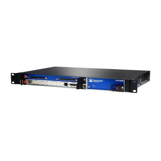
RS232 CTP2008 Platform The Juniper Networks CTP2008 Circuit to Packet platform is a 3-U high, full-rack wide chassis designed for tabletop or shelf installation. It can also be installed in a rack with the supplied rack-mounting kit. The CTP2008 platform has one removable interface module and one removable processor module, and is available in both AC-powered and DC-powered versions. -
Page 21: Ctp2024 Platform
DC version. There is no power redundancy for the AC version and the DC version. There are no power switches on CTP2000 Series DC models, so a readily accessible disconnect device must be provided as part of the electrical installation of the unit. -
Page 22: Figure 5: Ctp2024 Chassis Containing The Pp332 Processor
AC power supply modules, which keeps the chassis turned on in the event of failure of one of the power supplies. There are no power switches on CTP2000 Series DC models, so a readily accessible disconnect device must be provided as part of the electrical installation of the unit. -
Page 23: Ctp2056 Platform
CTP2056 Platform on page 7 CTP2056 Platform The Juniper Networks CTP2056 Circuit to Packet platform can have up to seven removable interface modules and one removable processor module, and is available in both AC-powered and DC-powered versions. It has a removable fan tray, and airflow is side-to-side. -
Page 24: Figure 8: Ctp2056 Chassis Containing The Pp332 Processor (Ac And Dc Version, Front View)
AC power supply modules, which keeps the chassis turned on in the event of failure of one of the power supplies. There are no power switches on CTP2000 Series DC models, so a readily accessible disconnect device must be provided as part of the electrical installation of the unit. -
Page 25: Figure 9: Ctp2056 Platform Containing The Pp332 Processor
Chapter 1: CTP2000 Series Platform Overview Ethernet connection—Provides the 1-Gbps Ethernet connection to the IP network by means of a local Ethernet switch or router. Console connection—Provides an asynchronous tty connection for locally configuring the CTP Series device. On the PP310 and PP332 processors, you can connect a console directly to the COM2 port (which is an RJ-45 type connector) found on the RTM panel. -
Page 26: Figure 10: Ctp2056 Platform Containing The Pp332 Processor (Dc Version, Rear View)
CTP2000 Hardware Documentation Figure 10: CTP2056 Platform Containing the PP332 Processor (DC Version, Rear View) Related CTP2008 Platform on page 4 Documentation CTP2024 Platform on page 5 Copyright © 2017, Juniper Networks, Inc. -
Page 27: Ctp2000 Series Interface Modules
CTP2000 Clock Interface Modules on page 25 CTP2000 Serial Interface Modules The Juniper Networks CTP2008, CTP2024, and CTP2056 Circuit to Packet platforms have up to one, three, and seven serial interface modules, respectively. The interface modules are interchangeable between the platforms. -
Page 28: Ctp2000 T1/E1 Interface Module
CTP2000 8P-IRIG Interface Module on page 25 CTP2000 T1/E1 Interface Module The CTP2000 Series T1/E1interface module has RJ-48 ports numbered 0–7 left to right. It provides a configurable eight-port E1 (2.048 MHz) or T1 (1.544 MHz) interface with AMI or B8ZS encoding. (See Figure 12 on page 12.) -
Page 29: Ctp2000 Compression 2 High Density Interface Module
CTP2000 Compression 2 High Density Interface Module on page 13 CTP2000 Compression 2 High Density Interface Module The CTP2000 Series Compression 2 High Density Interface Module enables serial data and voice bundles to be compressed and passed through a CTP2000 platform. It provides twice the digital signal processor (DSP) density of the original compression module. -
Page 30: Ctp2000 4We&M Interface Module
CTP2000 Hardware Documentation CTP2000 4WE&M Interface Module The CTP2000 Series 4WE&M interface module has eight 4-wire E&M ports and provides support for voice applications. It is used with voice compression (VCOMP) bundles in CTP2000 models and can be used only with a CTP2000 compression module. -
Page 31: Figure 16: Jumper Locations On The Rtm
Chapter 2: CTP2000 Series Interface Modules Figure 16: Jumper Locations on the RTM E&M type config jumpers Unused dual RJ-45 Figure 17: Jumper Positions for Signaling Types Type I Type II Pin 1 Type V NOTE: Jumper JP17 must be in Position 1-2 (see... - Page 32 The audio output pair for port 0 is R and T on pins 1 and 26. Table 4 on page 17 for signal definitions. See “CTP2000 4WE&M Interface Connector Pinouts” on page 43 for the connector A and B pinouts. Copyright © 2017, Juniper Networks, Inc.
-
Page 33: Supervisory Signaling
Chapter 2: CTP2000 Series Interface Modules Table 4: Signal Definitions Signal Name Signal Definition Port x T, R Audio transmit pair, 600 Ohm Port x T1, R1 Audio receive pair, 600 Ohm Port x E E lead–output Port x M M lead–input... -
Page 34: Figure 18: Analog 4We&M Signaling Types
E lead to SG. Note that two signaling units can be connected back-to-back if the appropriate signaling leads are swapped. With Type II signaling, the signaling unit and the trunk do not share a common ground. Copyright © 2017, Juniper Networks, Inc. -
Page 35: Ctp2000 2W-Fxs And 2W-Fxo Interface Modules
Chapter 2: CTP2000 Series Interface Modules Type V uses two leads, the E and M leads, for signaling. During inactivity, both the E and M leads are open. The CTP device signals off-hook by connecting the E lead to ground. -
Page 36: Required Cables And Pinouts
When a call is initiated from the CO (or FXS) side, the FXS interface puts an AC ring voltage on the R lead (typically 70-90 Vrms). This ring voltage generates the ringing that you hear on an analog phone. When the FXO device answers the call (someone picks up Copyright © 2017, Juniper Networks, Inc. -
Page 37: Answer Supervision
Chapter 2: CTP2000 Series Interface Modules the handset), the switch is closed between the T and R leads to complete a loop between the battery and ground in the FXS device. The FXS device detects the current, which flows from the battery (–48 V) through the R leads and back through the T leads to ground and stops the ring voltage. -
Page 38: Digital Signaling
In response to this toggling, the CTP device generates a ring voltage on the analog FXS interface. When the attached FXO device goes off-hook, the CTP FXS interface detects the off-hook, sets the A bit to 1, and stops the ring voltage. During the Copyright © 2017, Juniper Networks, Inc. -
Page 39: Digital Fxs/Fxo Ground-Start Signaling
Chapter 2: CTP2000 Series Interface Modules call, the CTP device sends A = B = 1 signaling bits. At the end of the call, the FXO device goes back to on-hook, the CTP detects the on-hook, sends out A=0 and B=1 signaling bits, and the circuit returns to the idle state. -
Page 40: Table 8: Ground-Start Signaling At Fxs Interface For Call Initiated By The Fxs
CTP2000 T1/E1 Interface Module on page 12 CTP2000 Compression Interface Module on page 12 CTP2000 Compression 2 High Density Interface Module on page 13 CTP2000 4WE&M Interface Module on page 14 CTP2000 8P-IRIG Interface Module on page 25 Copyright © 2017, Juniper Networks, Inc. -
Page 41: Ctp2000 8P-Irig Interface Module
Chapter 2: CTP2000 Series Interface Modules CTP2000 FXS and FXO Interface Module Cables and Pinouts on page 45 CTP2000 8P-IRIG Interface Module The CTP2000 8P-IRIG interface module enables an interrange instrumentation group time code (IRIG-B) signal to be transported through an IP network. IRIG-B is a special time code transmission format that uses a hybrid analog/digital physical interface. -
Page 42: Figure 24: Clock Main Module
DB-25 port. Each RJ-45 port can be connected to one spoke module. The spoke module has one ingress RJ-45 port and one DB-25 interface. (See Figure 24 on page Figure 25 on page 26, and Figure 26 on page 26.) Copyright © 2017, Juniper Networks, Inc. -
Page 43: External Reference Clock
Chapter 2: CTP2000 Series Interface Modules NOTE: BITS input is a T1/E1 line interface unit (LIU), with AMI (alternate mark inversion) encoding enabled and B8ZS/HDB3 (Zero Suppression) disabled. The equalization is set for a 0-133 feet cable. An internal 100 ohm termination is present, although it might need to be externally augmented based on the type of cabling used. - Page 44 CPU RTM in the chassis. Leaving the CPU RTM in the chassis will not adversely affect the functioning of the PP833 processor. Leaving the RTM installed will provide proper airflow within the CTP node. Copyright © 2017, Juniper Networks, Inc.
-
Page 45: Planning
PART 2 Planning System Specifications on page 31 Planning and Preparing the Site on page 37 Equipment Rack Requirements on page 39 Cable and Pinout Specifications on page 43 Copyright © 2017, Juniper Networks, Inc. - Page 46 CTP2000 Hardware Documentation Copyright © 2017, Juniper Networks, Inc.
-
Page 47: System Specifications
Ambient operating humidity 5% to 90% (noncondensing) DC Input Voltage –40 to –72 VDC Current 3A @ –48 VDC Power 144 W Redundancy (input power) 2 independent line feeds AC Input Power required 100–240 VAC Copyright © 2017, Juniper Networks, Inc. - Page 48 IECS-03 Issue 3 Class A FCC Part 15 Class A VCCI (Voluntary Control Council for Interference by Information Technology Equipment) Related CTP2024 Platform Specifications and Certification on page 33 Documentation CTP2056 Platform Specifications and Certification on page 34 Copyright © 2017, Juniper Networks, Inc.
-
Page 49: Ctp2024 Platform Specifications And Certification
3 ft. (90 cm) behind device or rack. Do not block air vents on the front or back of the device. Airflow Air intake occurs from the front of the device. Air is exhausted out the back of the device. Copyright © 2017, Juniper Networks, Inc. -
Page 50: Ctp2056 Platform Specifications And Certification
Table 12: CTP2056 Platform Specifications Category Specification Weight Chassis only 27 lb (12.25 kg) Dimensions Chassis only 7.0 in. (17.8 cm) high 17.25 in. (43.81 cm) wide 11.25 in. (28.57 cm) deep Environmental Requirements Copyright © 2017, Juniper Networks, Inc. - Page 51 Part 1: General Requirements IEC 60950-1(2001-10) Ed. 1.0 Information Technology Equipment - Safety - Part 1: General Requirements Low Voltage Directive (2006/95/EC) UL 60950-1, First Edition, Information Technology Equipment - Safety - Part 1: General Requirements Copyright © 2017, Juniper Networks, Inc.
- Page 52 IECS-03 Issue 3 Class A FCC Part 15 Class A VCCI (Voluntary Control Council for Interference by Information Technology Equipment) Related CTP2008 Platform Specifications and Certification on page 31 Documentation CTP2024 Platform Specifications and Certification on page 33 Copyright © 2017, Juniper Networks, Inc.
-
Page 53: Planning And Preparing The Site
CTP2000 Environmental Requirements on page 37 Before You Install a CTP Platform Before you install a Juniper Networks CTP Circuit to Packet platform: Verify that the electrical supply meets all power requirements. See the system specifications for the applicable CTP model. - Page 54 Be sure to allow enough space around the device for adequate ventilation. Inadequate ventilation can cause the device to overheat. CAUTION: Do not block the air vents on the device. Otherwise, the device might overheat. Related Before You Install a CTP Platform on page 37 Documentation Copyright © 2017, Juniper Networks, Inc.
-
Page 55: Equipment Rack Requirements
Select from the following rack options: Two-post rack—a freestanding enclosed cabinet with two mounting posts in the front Telco-type rack—two adjacent mounting posts that you must secure to the floor or an overhead structure Copyright © 2017, Juniper Networks, Inc. -
Page 56: Ctp2000 Space Requirements
EIA-310-D document. A fully loaded rack with three CTP2056 systems must structurally support at least 100 lb (46 kg). An optional mounting kit is available for midchassis mounting. Contact your Juniper Networks sales representative for more information. Related... - Page 57 Consider using cable-management brackets to keep network cables untangled and orderly and to prevent cables from hindering access to other slots. For additional cable recommendations, consult the document GR-63–CORE: Network Equipment Building System (NEBS) Requirements: Physical Protection, Issue 2, April 2002. Copyright © 2017, Juniper Networks, Inc.
- Page 58 CTP2000 Hardware Documentation Copyright © 2017, Juniper Networks, Inc.
-
Page 59: Cable And Pinout Specifications
CTP2000 FXS and FXO Interface Module Cables and Pinouts on page 45 T1/E1 Interface Module Pinouts on page 48 CTP2000 Serial Interface Module Pinouts on page 49 CTP2000 Series Console Cable Pinouts on page 58 CTP Fast Ethernet and Power Cables on page 63 CTP2000 4WE&M Interface Connector Pinouts CTP2000 4WE&M RTM Connector A Pinouts on page 43... -
Page 60: Ctp2000 4We&M Connector B Pinouts
Port 4 R1 Port 4 T1 Port 4 SG Port 4 E Port 4 SB Port 4 M Port 5 R Port 5 T Port 5 R1 Port 5 T1 Port 5 SG Port 5 E Copyright © 2017, Juniper Networks, Inc. -
Page 61: Ctp2000 Fxs And Fxo Interface Module Cables And Pinouts
CTP2000 4WE&M Interface Module on page 14 Documentation CTP2000 FXS and FXO Interface Module Cables and Pinouts on page 45 CTP2000 Series Console Cable Pinouts on page 58 CTP2000 FXS and FXO Interface Module Cables and Pinouts Required Cables on page 45... -
Page 62: Fxs Connector Pinouts
Port 3 R Port 3 T Port 4 R Port 4 T Port 5 R Port 5 T Port 6 R Port 6 T Port 7 R Port 7 T Port 8 R Port 8 T Copyright © 2017, Juniper Networks, Inc. -
Page 63: Fxo Connector Pinouts
RTM pinouts for the FXO module. Table 16: CTP2000 FXO Connector Pinouts on the RTM Signal Signal Port 0 T Port 0 R Port 1 T Port 1 R Port 2 T Port 2 R Copyright © 2017, Juniper Networks, Inc. -
Page 64: T1/E1 Interface Module Pinouts
CTP2000 2W-FXS and 2W-FXO Interface Modules on page 19 Documentation CTP2000 4WE&M Interface Connector Pinouts on page 43 CTP2000 Series Console Cable Pinouts on page 58 CTP Fast Ethernet and Power Cables on page 63 T1/E1 Interface Module Pinouts Table 17 on page 48 lists the T1/E1 interface module pinouts for the RJ-45 connector. -
Page 65: Ctp2000 Serial Interface Module Pinouts
CTP2000 T1/E1 Interface Module on page 12 Documentation CTP2000 FXS and FXO Interface Module Cables and Pinouts on page 45 CTP2000 Series Console Cable Pinouts on page 58 CTP2000 Serial Interface Module Pinouts Figure 28 on page 49 displays the serial DCE/DTE cable pin configurations for CTP2000 series devices. -
Page 66: Table 18: Ctp2000 Serial Dce Cable Pinouts
Table 18: CTP2000 Serial DCE Cable Pinouts Cable J1 SCSI DB-25 P0-2 P0-14 P0-20 P0-23 P0-4 P0-19 P0-15 P0-12 P0-16 P0-3 P0-22 P0-6 P0-13 P0-5 P0-8 P0-25 P0-9 P0-10 P0-18 P0-17 P0-24 P0-11 P0-7 P0-21 Copyright © 2017, Juniper Networks, Inc. - Page 67 Table 18: CTP2000 Serial DCE Cable Pinouts (continued) Cable J1 SCSI DB-25 P0-1 P1-14 P1-2 P1-23 P1-20 P1-19 P1-4 P1-12 P1-15 P1-3 P1-16 P1-6 P1-22 P1-5 P1-13 P1-25 P1-8 P1-10 P1-9 P1-17 P1-18 P1-11 P1-24 P1-21 Copyright © 2017, Juniper Networks, Inc.
- Page 68 Table 18: CTP2000 Serial DCE Cable Pinouts (continued) Cable J1 SCSI DB-25 P1-7 P1-1 P2-2 P2-14 P2-20 P2-23 P2-4 P2-19 P2-15 P2-12 P2-16 P2-3 P2-22 P2-6 P2-13 P2-5 P2-8 P2-25 P2-9 P2-10 P2-18 P2-17 P2-24 P2-11 Copyright © 2017, Juniper Networks, Inc.
- Page 69 Table 18: CTP2000 Serial DCE Cable Pinouts (continued) Cable J1 SCSI DB-25 P2-7 P2-21 P2-1 P3-14 P3-2 P3-23 P3-20 P3-19 P3-4 P3-12 P3-15 P3-3 P3-16 P3-6 P3-22 P3-5 P3-13 P3-25 P3-8 P3-10 P3-9 P3-17 P3-18 P3-11 Copyright © 2017, Juniper Networks, Inc.
-
Page 70: Table 19: Ctp2000 Serial Dte Cable Pinouts
CTP2000 serial DTE cable pinouts. Table 19: CTP2000 Serial DTE Cable Pinouts Cable J1 SCSI DB-25 P0-3 P0-16 P0-6 P0-22 P0-5 P0-13 P0-15 P0-12 P0-14 P0-2 P0-23 P0-20 P0-19 P0-4 P0-8 P0-21 P0-11 Copyright © 2017, Juniper Networks, Inc. - Page 71 Table 19: CTP2000 Serial DTE Cable Pinouts (continued) Cable J1 SCSI DB-25 P0-10 P0-18 P0-24 P0-17 P0-9 P0-7 P0-25 P0-1 P1-16 P1-3 P1-22 P1-6 P1-13 P1-5 P1-12 P1-15 P1-2 P1-14 P1-20 P1-23 P1-4 P1-19 P1-21 P1-8 Copyright © 2017, Juniper Networks, Inc.
- Page 72 Table 19: CTP2000 Serial DTE Cable Pinouts (continued) Cable J1 SCSI DB-25 P1-10 P1-11 P1-24 P1-18 P1-9 P1-17 P1-25 P1-7 P1-1 P2-3 P2-16 P2-6 P2-22 P2-5 P2-13 P2-15 P2-12 P2-14 P2-2 P2-23 P2-20 P2-19 P2-4 P2-8 Copyright © 2017, Juniper Networks, Inc.
- Page 73 Table 19: CTP2000 Serial DTE Cable Pinouts (continued) Cable J1 SCSI DB-25 P2-21 P2-11 P2-10 P2-18 P2-24 P2-17 P2-9 P2-7 P2-25 P2-1 P3-16 P3-3 P3-22 P3-6 P3-13 P3-5 P3-12 P3-15 P3-2 P3-14 P3-20 P3-23 P3-4 P3-19 Copyright © 2017, Juniper Networks, Inc.
-
Page 74: Ctp2000 Series Console Cable Pinouts
The console port CTP2008, CTP2024, and CTP2056 devices with the new PP833 processor uses a USB-type connector located on the right of the PP833 faceplate labelled “RS-232”. CTP2000 series devices with the PP310 and PP332 processors use an RJ-45 connected to the port. -
Page 75: Table 20: Ctp2000 Series Console Cable Pinouts For Pp310 And Pp332
6 (tied to pin 7) RXD 1 DCD 7 DSR 4 DTR 8 CTS 7 RTS Table 21: CTP2000 Series Console Cable (p/n 720-071594) Pinouts for the PP833 Processor USB Console Connector DB-9 Male 2 RXD 3 TXD 3 TXD... - Page 76 USB-to-DB9 cable (p/n 720-071594), in which the DB-9 connector has the same pinout as a standard RS-232 DTE port. When the USB-to-DB9 cable is used in conjunction with the DB-9 adapter labelled “p/n 450-071855” (see Copyright © 2017, Juniper Networks, Inc.
-
Page 77: Figure 30: Upgrading From Pp310/Pp332 Processor To Pp833 Processor
62) is used instead of “p/n 450-071855”, the available RJ-45 console pinout will be similar to the CTP150 console port (and other Juniper routers). To connect the PP833 processor with the DB-9 male serial port of a PC, additionally connect a straight RJ-45 cable with the DB-9 adapter from the bag labelled “p/n 720-056657”. -
Page 78: Figure 31: Connecting The Pp833 Processor With The Rj-45 Serial Console
RJ-45 male end of user’s console cable 3— DB-9 male end of 720-071594 6— User’s cable that connects to the console on a CTP150 or other Juniper product Figure 32: Connecting the PP833 Processor with the PC DB-9M Serial Console 1— PP833 front panel 6—... -
Page 79: Ctp Fast Ethernet And Power Cables
DC Power Cables For CTP chassis with DC power options, we recommend 18-AWG power cables. Copyright © 2017, Juniper Networks, Inc. - Page 80 CTP2000 Hardware Documentation Copyright © 2017, Juniper Networks, Inc.
-
Page 81: Safety
PART 3 Safety General Safety Guidelines and Warnings on page 67 Module Installation Safety Guidelines and Warnings on page 69 Hardware Compliance on page 71 Copyright © 2017, Juniper Networks, Inc. - Page 82 CTP2000 Hardware Documentation Copyright © 2017, Juniper Networks, Inc.
-
Page 83: General Safety Guidelines And Warnings
Connect the device or rack to ground (earth), and ensure that a reliable grounding path is maintained in the rack. WARNING: Do not work on the device or connect or disconnect cables during lightning activity. Copyright © 2017, Juniper Networks, Inc. - Page 84 FCC Requirements for Consumer Products on page 73 Food and Drug Administration, Center for Devices and Radiological Health on page 74 Compliance with Canadian Regulations on page 74 Before You Install a CTP Platform on page 37 Copyright © 2017, Juniper Networks, Inc.
-
Page 85: Module Installation Safety Guidelines And Warnings
WARNING: Never attempt to repair parts of modules yourself. Only trained customer service personnel are authorized to service parts. Call Juniper Networks Customer Service to make arrangements to return defective modules for repair. Copyright © 2017, Juniper Networks, Inc. - Page 86 Federal Communications Commission (FCC) Statement on page 73 FCC Requirements for Consumer Products on page 73 Food and Drug Administration, Center for Devices and Radiological Health on page 74 Compliance with Canadian Regulations on page 74 Copyright © 2017, Juniper Networks, Inc.
-
Page 87: Hardware Compliance
Food and Drug Administration, Center for Devices and Radiological Health on page 74 Compliance with Canadian Regulations on page 74 Declaration of Conformity for CTP2000 Platforms Figure 33 on page 72 shows the Declaration of Conformity for the CTP2000 platforms. Copyright © 2017, Juniper Networks, Inc. -
Page 88: Figure 33: Ctp2000 Declaration Of Conformity
CTP2000 Hardware Documentation Figure 33: CTP2000 Declaration of Conformity Related CTP2008 Platform Specifications and Certification on page 31 Documentation CTP2024 Platform Specifications and Certification on page 33 CTP2056 Platform Specifications and Certification on page 34 Copyright © 2017, Juniper Networks, Inc. -
Page 89: Federal Communications Commission (Fcc) Statement
Related Federal Communications Commission (FCC) Statement on page 73 Documentation Food and Drug Administration, Center for Devices and Radiological Health on page 74 Compliance with Canadian Regulations on page 74 Copyright © 2017, Juniper Networks, Inc. -
Page 90: Food And Drug Administration, Center For Devices And Radiological Health
The termination on an interface may consist of any combination of devices subject only to the requirement that the sum of the Ringer Equivalence Numbers of all the devices does not exceed 5. Copyright © 2017, Juniper Networks, Inc. -
Page 91: Avis Cs-03 D'industrie Canada
In some cases, the company's inside wiring associated with a single line individual service may be extended by means of a certified connector assembly (telephone extension cord). The customer should be aware Copyright © 2017, Juniper Networks, Inc. - Page 92 électricien, selon le cas. Related Federal Communications Commission (FCC) Statement on page 73 Documentation FCC Requirements for Consumer Products on page 73 Food and Drug Administration, Center for Devices and Radiological Health on page 74 Copyright © 2017, Juniper Networks, Inc.
- Page 93 Installing and Removing SFPs in a CTP Module on page 95 Upgrading Components for Memory Upgrades on page 99 Cabling on page 101 Powering On on page 107 Accessing the CTP2000 Platform on page 111 Copyright © 2017, Juniper Networks, Inc.
- Page 94 CTP2000 Hardware Documentation Copyright © 2017, Juniper Networks, Inc.
-
Page 95: Unpacking And Inspecting The Ctp Platform
Inspecting Platform Components and Accessories on page 80 If You Detect or Suspect Damage on page 80 Contacting Juniper Networks on page 81 Before You Unpack the CTP Platform Before you begin unpacking the device, be sure you have the following tools: No. -
Page 96: Inspecting Platform Components And Accessories
If You Detect or Suspect Damage If you detect or suspect damage to any equipment: Contact the shipper responsible for delivery, and formally report the damage. Contact your Juniper Networks sales representative or reseller. Related Before You Unpack the CTP Platform on page 79... -
Page 97: Contacting Juniper Networks
Inspecting Platform Components and Accessories on page 80 Contacting Juniper Networks on page 81 Contacting Juniper Networks Please contact Juniper Networks at 1-888-314-JTAC (from the United States, Canada, or Mexico) or 1-408-745-9500 (from elsewhere), or contact your sales representative if you have any questions or concerns. See “Contacting Customer Support”... - Page 98 CTP2000 Hardware Documentation Copyright © 2017, Juniper Networks, Inc.
-
Page 99: Installing The Chassis
When installing the device on a table top or in any other freestanding mode, be sure to leave enough space around the device for adequate ventilation. Position the chassis with easy access to the connections that it needs for power, local communications, and remote communications. Copyright © 2017, Juniper Networks, Inc. -
Page 100: Special Guidelines For Installing Ctp2056 Chassis In A Rack
Position the device in its designated location in the equipment rack. Make sure the holes of the mounting brackets align evenly with the holes of the equipment rack on both sides. Copyright © 2017, Juniper Networks, Inc. - Page 101 Related Before You Install the CTP2000 Platform on page 83 Documentation Installing the CTP2000 Platform in Freestanding Mode on page 83 Cabling the CTP2000 Platform Overview on page 101 Copyright © 2017, Juniper Networks, Inc.
- Page 102 CTP2000 Hardware Documentation Copyright © 2017, Juniper Networks, Inc.
-
Page 103: Installing Modules
Installing a CTP Interface Module, Processor Module, or Clock Module on page 89 Removing a CTP Interface Module, Processor Module, or Clock Module on page 89 Installing or Removing a CTP2000 Series CompactFlash Card on page 90 Installing a PMC on CTP2000 Platforms on page 92... -
Page 104: Required Tools And Safety Items For Installing Ctp Modules
Flathead screwdriver ESD wrist strap or other grounding device Related Safety Guidelines and Warnings for Installing CTP Modules on page 69 Documentation Installing a CTP Interface Module, Processor Module, or Clock Module on page 89 Copyright © 2017, Juniper Networks, Inc. -
Page 105: Installing A Ctp Interface Module, Processor Module, Or Clock Module
Removing a CTP Interface Module, Processor Module, or Clock Module on page 89 Documentation Removing a CTP Interface Module, Processor Module, or Clock Module NOTE: We recommend that you issue the slot disable command from the CLI before removing a line module. Copyright © 2017, Juniper Networks, Inc. -
Page 106: Installing Or Removing A Ctp2000 Series Compactflash Card
CompactFlash card is installed on the processor rear transition module (RTM). Some CTP devices may ship with a CompactFlash card already installed. To remove or install the CompactFlash card for the CTP2000 series with the new PP833 processor (see Figure 34 on page 91): Power off the unit. -
Page 107: Figure 34: Installing Compactflash On The Pp833 Processor
Chapter 12: Installing Modules Figure 34: Installing CompactFlash on the PP833 processor To remove or install the CompactFlash card for the CTP2000 series with the PP310 and PP332 processors (see Figure 35 on page 91): Power off the unit. Remove the processor RTM by unscrewing the retaining screws and pushing the extractors outward with the latching buttons depressed. -
Page 108: Installing A Pmc On Ctp2000 Platforms
Gently press the PMC into the processor module. From the back of the processor module, use the four Phillips head screws to secure the two PMC standoff posts and PMC front assembly to the processor module. Reinstall the processor. Copyright © 2017, Juniper Networks, Inc. - Page 109 Chapter 12: Installing Modules Related Installing a CTP Interface Module, Processor Module, or Clock Module on page 89 Documentation Copyright © 2017, Juniper Networks, Inc.
- Page 110 CTP2000 Hardware Documentation Copyright © 2017, Juniper Networks, Inc.
-
Page 111: Installing And Removing Sfps In A Ctp Module
Ground yourself by using an antistatic wrist strap or other device, and connect it to an ESD grounding jack. Identify the following items on the SFP (Figure 37 on page 96): The connection circuitry on the base The cable connectors on the front Copyright © 2017, Juniper Networks, Inc. -
Page 112: Removing Sfps In A Ctp2000 Module
Obtain an antistatic container for the SFP you plan to remove. Ground yourself by using an antistatic wrist strap or other device, and connect it to an ESD grounding jack. Disconnect the cable from the SFP on the module. Copyright © 2017, Juniper Networks, Inc. -
Page 113: Figure 38: Possible Release Mechanisms On The Sfp
Figure 38: Possible Release Mechanisms on the SFP Release the SFP and pull it out of the slot. Place the SFP into an antistatic bag. Related Installing SFPs in a CTP2000 Module on page 95 Documentation Copyright © 2017, Juniper Networks, Inc. - Page 114 CTP2000 Hardware Documentation Copyright © 2017, Juniper Networks, Inc.
-
Page 115: Upgrading Components For Memory Upgrades
Upgrading CTP2000 Series Components for Memory Upgrades on page 99 Upgrading CTP2000 Series Components for Memory Upgrades Certain CTP2000 Series components need to be upgraded when RAM memory is increased, as required by certain JUNOS version updates. The affected modules and... - Page 116 Failure to do this can make it difficult to install adjacent modules. Go to Cabling a CTP Interface Module. Related Removing a CTP Interface Module, Processor Module, or Clock Module on page 89 Documentation Copyright © 2017, Juniper Networks, Inc.
-
Page 117: Cabling
Connect grounding wires to the chassis. Connect the power cables from the power source to the power supply. Connect the interface modules to their appropriate network interface. For more information about CTP2000 Series cable and pinout specifications, refer Cable and Pinout Specifications. Related... -
Page 118: Required Tools, Wires, And Cables For The Ctp2000 Platform
Cabling a CTP2000 Interface Module on page 103 CTP2000 Management Ports The management section of the CTP2000 series has one port for management access, a 10/100Base-T Ethernet port that accepts an RJ-45 (male) connector, providing an out-of-band connection for LAN access through an SSH session or SNMP. -
Page 119: Cabling A Ctp2000 Interface Module
CTP2000 Management Ports on page 102 Cabling the CTP Platform for DC Power After you have correctly cabled the RTM for the CTP2000 Series, you must attach grounding and electrical wires before you turn the device on. Three main tasks are involved: Push the power switch to . -
Page 120: Task 1: Turning Off All Ctp Platform Power
When grounding the device, leave a service loop in the grounding cable to ensure that the grounding cable is the last cable to disconnect from the shelf if strain is placed on the electrical cables. Copyright © 2017, Juniper Networks, Inc. -
Page 121: Task 3: Connecting The Power Cables To The Ctp2000 Platform
To provide redundancy, do not use the same power source for Power A and Power B leads. Repeat Steps 1–7 for each power supply module in your configuration. For more information about CTP2000 Series cable and pinout specifications, refer Cable and Pinout Specifications. Related... - Page 122 CTP2000 Hardware Documentation Copyright © 2017, Juniper Networks, Inc.
-
Page 123: Powering On
If using a DC power supply, see “Cabling the CTP Platform for DC Power” on page 103. For specifications on the electrical requirements for the device, see one of the following topics: CTP2008 Platform Specifications and Certification on page 31 Copyright © 2017, Juniper Networks, Inc. - Page 124 Date and time GMT (more precisely, UTC)—Enter these separately in digits for the month, day, hour, and minutes in Coordinated Universal Time (UTC), or accept the internal settings. The device goes into startup mode. Copyright © 2017, Juniper Networks, Inc.
- Page 125 Setting the date (GMT). Please input the day [1-31] (return for 11): Setting the date (GMT). Please input the hour [0-23] (return for 20): Setting the date (GMT). Please input the minute [0-59] (return for 22): INIT: Entering runlevel: 3 Entering non-interactive startup Copyright © 2017, Juniper Networks, Inc.
-
Page 126: Powering Off The Ctp Platform
CompactFlash card might become corrupted. To power off the device from the CTP Menu: From the Main Menu, select 5) Node Operations. From the Node Operations Menu, select 10) Powerdown Node. Copyright © 2017, Juniper Networks, Inc. -
Page 127: Accessing The Ctp2000 Platform
“p/n 450-071855”, the available RJ-45 console pinout will be similar to the CTP150 console port (and other Juniper routers). To connect the PP833 processor with the DB-9 male serial port of a PC, additionally connect a straight RJ-45 cable with the DB-9 adapter from the bag labelled “p/n 720-056657”. -
Page 128: Ctp2000 Console Port Setup
“p/n 450-071855”, the available RJ-45 console pinout will be similar to the CTP150 console port (and other Juniper routers). To connect the PP833 processor with the DB-9 male serial port of a PC, additionally connect a straight RJ-45 cable with the DB-9 adapter from the bag labelled “p/n 720-056657”. -
Page 129: Using Hyperterminal With The Ctp2000 Platform
To connect a console directly to the device: Connect the female DB-9 connector to the COM 2 port on the device’s RTM. Connect the crossover adapter connector to your PC's serial port. Power on the device. Copyright © 2017, Juniper Networks, Inc. -
Page 130: Ctp2000 Platform Ssh Setup
Setting Up Management Access on the CTP2000 Platform on page 111 Documentation CTP2000 Console Port Setup on page 112 Using HyperTerminal with the CTP2000 Platform on page 113 Connecting Directly to the CTP2000 Platform on page 113 Copyright © 2017, Juniper Networks, Inc. - Page 131 Maintenance Maintaining Components on page 117 Replacing Interface Modules Using Hot-Swap on page 121 Product Reclamation and Recycling on page 123 Replacing Fan Trays on page 125 Packing and Returning Hardware on page 127 Copyright © 2017, Juniper Networks, Inc.
- Page 132 CTP2000 Hardware Documentation Copyright © 2017, Juniper Networks, Inc.
-
Page 133: Maintaining Components
Components, such as transceivers and CompactFlash cards, are shipped in antistatic plastic containers within an antistatic padded box. CAUTION: Failure to store electronic modules and components correctly can lead to damage of these items. Follow these guidelines for storing modules and other components: Copyright © 2017, Juniper Networks, Inc. -
Page 134: Cleaning The Ctp Platform
If you remove a power supply, you must install a replacement power supply or a blank panel shortly after the removal. After powering off a power supply, wait at least 60 seconds before turning it back on. Copyright © 2017, Juniper Networks, Inc. -
Page 135: Figure 39: Replacing An Ac Power Supply
PS FAIL LED is not lit. Related Required Tools for Maintaining the CTP Platform on page 117 Documentation Storing CTP Modules and Other Components on page 117 Cleaning the CTP Platform on page 118 Copyright © 2017, Juniper Networks, Inc. - Page 136 CTP2000 Hardware Documentation Copyright © 2017, Juniper Networks, Inc.
-
Page 137: Replacing Interface Modules Using Hot-Swap
(CTP2000-IM-8P-T1) CTP2000 8-port serial interface module, including a configurable 4WTO interface (CTP2000-IM-8P-V) CTP2000 Series T1/E1interface module (CTP2000-IM-8P-T1E1) Before performing a hot-swap, be aware of the following restrictions: Hot-swapping works most efficiently when your interface module is the same type as the interface module being replaced. - Page 138 Quit the current menu session before resuming work by opening a new menu session. Related CTP2000 Serial Interface Modules on page 11 Documentation CTP2000 T1/E1 Interface Module on page 12 Copyright © 2017, Juniper Networks, Inc.
-
Page 139: Product Reclamation And Recycling
Product Reclamation and Recycling Program on page 123 Product Reclamation and Recycling Program Juniper Networks is committed to environmentally responsible behavior. As part of this commitment, we continually work to comply with environmental standards such as the European Union’s Waste Electrical and Electronic Equipment (WEEE) Directive and Restriction of Hazardous Substances (RoHS) Directive. - Page 140 Our packaging is designed to be recycled and should be handled in accordance with your local recycling policies. Related Return Procedure on page 127 Documentation Returning CTP Products for Repair or Replacement on page 127 Copyright © 2017, Juniper Networks, Inc.
-
Page 141: Replacing Fan Trays
With an appropriate screwdriver, tighten the captive screws. Alternate between screws when tightening them to ensure that the electrical connectors at the back of the tray fit tightly. Copyright © 2017, Juniper Networks, Inc. - Page 142 CTP2000 Hardware Documentation Related Removing a CTP2000 Fan Tray on page 125 Documentation Copyright © 2017, Juniper Networks, Inc.
-
Page 143: Packing And Returning Hardware
Contacting Customer Support on page 133 Returning CTP Products for Repair or Replacement In the event of a hardware failure, please contact Juniper Networks to obtain a Return Material Authorization (RMA) number. This number is necessary to ensure proper tracking and handling of returned material at the factory. - Page 144 CTP2000 Hardware Documentation have received an RMA. Juniper Networks reserves the right to refuse shipments that do not have an RMA. Refused shipments are returned to the shipper through collect freight. If possible, use the original shipping crate, pallet, and packing materials in which the chassis was originally shipped.
-
Page 145: Troubleshooting
PART 6 Troubleshooting Troubleshooting Power Failures on page 131 Contacting Customer Support on page 133 Copyright © 2017, Juniper Networks, Inc. - Page 146 CTP2000 Hardware Documentation Copyright © 2017, Juniper Networks, Inc.
-
Page 147: Troubleshooting Power Failures
Verify that the power supply is delivering the correct voltage, current, and wattage to the device. See the system specifications for your particular CTP platform. If the platform still does not operate, contact the Juniper Networks Technical Assistance Center (JTAC). - Page 148 Look to see whether or not the LEDs are lit. Run diagnostics using the CLI. If the device does not reset, contact JTAC. Related CTP Platform Does Not Power On on page 131 Documentation Copyright © 2017, Juniper Networks, Inc.
-
Page 149: Contacting Customer Support
Locating CTP Component Serial Numbers on page 133 Information You Might Need to Supply to JTAC on page 134 Contacting Customer Support See the Juniper Networks Web site for complete customer service information: http://www.juniper.net/support/guidelines.html For your convenience, we provide multiple options for requesting and receiving technical support from the Juniper Networks Technical Assistance Center (JTAC): By the Web using Juniper Networks, Inc. -
Page 150: Information You Might Need To Supply To Jtac
Closes the case when you agree that the problem has been resolved. Related Contacting Customer Support on page 133 Documentation Return Procedure on page 127 Locating CTP Component Serial Numbers on page 133 Returning CTP Products for Repair or Replacement on page 127 Copyright © 2017, Juniper Networks, Inc.
Need help?
Do you have a question about the CTP2000 Series and is the answer not in the manual?
Questions and answers