Sign In
Upload
Manuals
Brands
Juniper Manuals
Chassis
CTP2000 Series
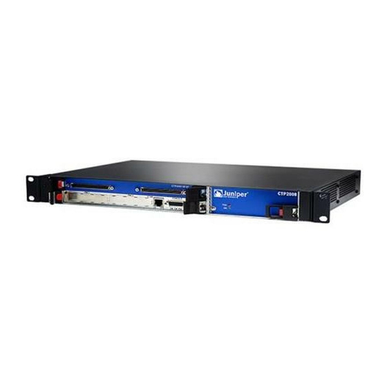
Juniper CTP2000 Series Manuals
Manuals and User Guides for Juniper CTP2000 Series. We have
5
Juniper CTP2000 Series manuals available for free PDF download: Hardware Documentation, Hardware Manual, Quick Start Manual, Upgrade
Juniper CTP2000 Series Hardware Documentation (150 pages)
Brand:
Juniper
| Category:
Network Router
| Size: 2.15 MB
Table of Contents
Table of Contents
3
About the Documentation
11
Documentation and Release Notes
11
Documentation Conventions
11
Table 1: Notice Icons
12
Table 2: Text and Syntax Conventions
12
Documentation Feedback
13
About the Documentation
13
Requesting Technical Support
14
Self-Help Online Tools and Resources
14
Opening a Case with JTAC
14
CTP2000 Series Interface Modules
17
CTP2000 Series Platform Overview
17
Overview
17
Chapter 1 CTP2000 Series Platform Overview
19
Introducing CTP Platforms
19
CTP2000 Series Processor
19
CTP2008 Platform
20
Figure 1: PP833 Processor (AC and DC Version, Front View)
20
Figure 2: CTP2008 Chassis Containing the PP332 Processor (AC and DC Version, Front View)
20
Interface
20
CTP2024 Platform
21
Figure 3: CTP2008 Platform Containing the PP332 Processor
21
Figure 4: CTP2008 Platform Containing the PP332 Processor
21
Figure 5: CTP2024 Chassis Containing the PP332 Processor
22
CTP2056 Platform
23
Figure 6: CTP2024 Platform Containing the PP332 Processor
23
Figure 7: CTP2024 Platform Containing the PP332 Processor
23
Interface
23
Figure 8: CTP2056 Chassis Containing the PP332 Processor (AC and DC Version, Front View)
24
Interface
24
Figure 9: CTP2056 Platform Containing the PP332 Processor
25
Figure 10: CTP2056 Platform Containing the PP332 Processor (DC Version, Rear View)
26
Chapter 2 CTP2000 Series Interface Modules
27
CTP2000 Serial Interface Modules
27
Figure 11: Sample Serial Interface Module
27
CTP2000 T1/E1 Interface Module
28
CTP2000 Compression Interface Module
28
Figure 12: CTP2000 IM-8P-T1/E1 Interface Module
28
Figure 13: Compression Interface Module
28
CTP2000 Compression 2 High Density Interface Module
29
CTP2000 4WE&M Interface Module
30
Figure 14: CTP2000 4WE&M Module
30
Figure 15: 4WE&M RTM
30
Figure 16: Jumper Locations on the RTM
31
Figure 17: Jumper Positions for Signaling Types
31
Table 3: Jumper Positions for Configuring Port Signaling Type
31
Supervisory Signaling
33
Table 4: Signal Definitions
33
Figure 18: Analog 4WE&M Signaling Types
34
CTP2000 2W-FXS and 2W-FXO Interface Modules
35
Table 5: Supported Signaling Types for the CTP2000 4WE&M Module
35
Analog FXS/FXO Loop-Start Signaling
36
Figure 19: Front Panel of CTP2000 2W-FXS Interface Module
36
Figure 20: Rear Panel of CTP2000 2W-FXS RTM
36
Figure 21: Front Panel of CTP2000 2W-FXO Interface Module
36
Figure 22: Rear Panel of CTP2000 2W-FXO RTM
36
Answer Supervision
37
Disconnect Supervision
37
Required Cables and Pinouts
36
Analog FXS/FXO Ground-Start Signaling
37
Digital Signaling
38
Digital FXS/FXO Loop-Start Signaling
38
Digital FXS/FXO Ground-Start Signaling
39
Table 6: Ground-Start Signaling at FXO Interface for Call Initiated by the FXO
39
Table 7: Ground-Start Signaling at FXO Interface for Call Initiated by the FXS
39
Table 8: Ground-Start Signaling at FXS Interface for Call Initiated by the FXS
40
Table 9: Ground-Start Signaling at FXS Interface for Call Initiated by the FXO
40
CTP2000 8P-IRIG Interface Module
41
CTP2000 Clock Interface Modules
41
Figure 23: CTP2000 8P-IRIG Interface Module
41
Interface
41
Figure 24: Clock Main Module
42
Figure 25: Clock Spoke Module
42
Figure 26: Hub-And-Spoke Setup
42
External Reference Clock
43
Installation Notes for Clock Interface Modules
43
Planning
45
System Specifications
45
Cable and Pinout Specifications
45
Chapter 3 System Specifications
47
CTP2008 Platform Specifications and Certification
47
Table 10: CTP2008 Platform Specifications
47
CTP2024 Platform Specifications and Certification
49
Table 11: CTP2024 Platform Specifications
49
CTP2056 Platform Specifications and Certification
50
Table 12: CTP2056 Platform Specifications
50
Chapter 4 Planning and Preparing the Site
53
Before You Install a CTP Platform
53
CTP2000 Environmental Requirements
53
Chapter 5 Equipment Rack Requirements
55
CTP2000 Rack Requirements
55
CTP2000 Mechanical Requirements
55
CTP2000 Space Requirements
56
CTP2000 Rack Installation
56
CTP Cabling Recommendations
56
Chapter 6 Cable and Pinout Specifications
59
CTP2000 4WE&M Interface Connector Pinouts
59
CTP2000 4WE&M RTM Connector a Pinouts
59
Table 13: CTP2000 4WE&M RTM Pinouts-Connector a
59
CTP2000 4WE&M Connector B Pinouts
60
Table 14: CTP2000 4WE&M RTM Pinouts-Connector B
60
CTP2000 FXS and FXO Interface Module Cables and Pinouts
61
Required Cables
61
RTM Pinout Locations
61
FXS Connector Pinouts
62
Figure 27: RTM Pinouts for CTP2000 2W-FXS and 2W-FXO Interface
62
Table 15: CTP2000 FXS Connector Pinouts on the RTM
62
FXO Connector Pinouts
63
Table 16: CTP2000 FXO Connector Pinouts on the RTM
63
T1/E1 Interface Module Pinouts
64
Table 17: T1/E1 Interface Module-RJ-45 Connector Pinout
64
CTP2000 Serial Interface Module Pinouts
65
Figure 28: CTP2000 Serial DCE/DTE Cable Pin Configurations
65
Table 18: CTP2000 Serial DCE Cable Pinouts
66
Table 19: CTP2000 Serial DTE Cable Pinouts
70
CTP2000 Series Console Cable Pinouts
74
Table 20: CTP2000 Series Console Cable Pinouts for PP310 and PP332
75
Table 21: CTP2000 Series Console Cable (P/N 720-071594) Pinouts for the
75
Figure 30: Upgrading from PP310/PP332 Processor to PP833 Processor
77
Figure 31: Connecting the PP833 Processor with the RJ-45 Serial Console
78
Figure 32: Connecting the PP833 Processor with the PC DB-9M Serial
78
CTP Fast Ethernet and Power Cables
79
Fast Ethernet Cables
79
DC Power Cables
79
Safety
81
Chapter 7 General Safety Guidelines and Warnings
83
CTP Safety Guidelines and Warnings
83
Chapter 8 Module Installation Safety Guidelines and Warnings
85
Safety Guidelines and Warnings for Installing CTP Modules
85
Chapter 9 Hardware Compliance
87
Declaration of Conformity for CTP2000 Platforms
87
Figure 33: CTP2000 Declaration of Conformity
88
Federal Communications Commission (FCC) Statement
89
FCC Requirements for Consumer Products
89
Food and Drug Administration, Center for Devices and Radiological Health
90
Compliance with Canadian Regulations
90
Industry Canada Notice
90
Industry Canada Notice CS-03
90
Avis CS-03 D'industrie Canada
91
Canadian Department of Communications Explanatory Notes
91
DOC Explanatory Notes: Equipment Attachment Limitations
91
Notes Explicatives du Ministère des Communications: Limites Visant les
91
Accessoires
91
Chapter 10 Unpacking and Inspecting the CTP Platform
95
Before You Unpack the CTP Platform
95
Unpacking the CTP Device
95
Inspecting Platform Components and Accessories
96
If You Detect or Suspect Damage
96
Contacting Juniper Networks
97
Chapter 11 Installing the Chassis
99
Before You Install the CTP2000 Platform
99
Installing the CTP2000 Platform in Freestanding Mode
99
Special Guidelines for Installing CTP2056 Chassis in a Rack
100
Installing the CTP2000 Platform in a Rack
100
Chapter 12 Installing Modules
103
CTP2000 Modules Installation Overview
103
Protecting CTP2000 Modules and Slots
103
Required Tools and Safety Items for Installing CTP Modules
104
Installing a CTP Interface Module, Processor Module, or Clock Module
105
Removing a CTP Interface Module, Processor Module, or Clock Module
105
Installing or Removing a CTP2000 Series Compactflash Card
106
Figure 34: Installing Compactflash on the PP833 Processor
107
Figure 35: Compactflash on the RTM
107
Installing a PMC on CTP2000 Platforms
108
Figure 36: CTP2000 Platforms PMC Location
108
Installing a CTP Interface Module, Processor Module, or Clock Module
108
Chapter 13 Installing and Removing Sfps in a CTP Module
111
Installing Sfps in a CTP2000 Module
111
Removing Sfps in a CTP2000 Module
112
Figure 37: Representative SFP
112
Figure 38: Possible Release Mechanisms on the SFP
113
Chapter 14 Upgrading Components for Memory Upgrades
115
Upgrading CTP2000 Series Components for Memory Upgrades
115
Chapter 15 Cabling
117
Cabling the CTP2000 Platform Overview
117
Required Tools, Wires, and Cables for the CTP2000 Platform
118
CTP2000 Management Ports
118
Cabling a CTP2000 Interface Module
119
Cabling the CTP Platform for DC Power
119
And Pinout Specifications
119
Connect Grounding Wires to the Chassis
119
CTP2000 Management Ports
119
Task 1: Turning off All CTP Platform Power
120
Task 2: Connecting the Grounding Cable to the CTP Platform (CTP2056 Platform Only)
120
Cabling a CTP2000 Interface Module
121
Task 3: Connecting the Power Cables to the CTP2000 Platform
121
Chapter 16 Powering on
123
Before You Power on the CTP2000 Platform
123
Powering on the CTP2000 Platform
123
Powering off the CTP Platform
126
Chapter 17 Accessing the CTP2000 Platform
127
Setting up Management Access on the CTP2000 Platform
127
CTP2000 Console Port Setup
128
Using Hyperterminal with the CTP2000 Platform
129
Connecting Directly to the CTP2000 Platform
129
CTP2000 Platform SSH Setup
130
Chapter 18 Maintaining Components
133
Required Tools for Maintaining the CTP Platform
133
Storing CTP Modules and Other Components
133
Cleaning the CTP Platform
134
Replacing an AC Power Supply
134
Figure 39: Replacing an AC Power Supply
135
Chapter 19 Replacing Interface Modules Using Hot-Swap
137
CTP2000 Hot-Swap Interface Module Replacement
137
Chapter 20 Product Reclamation and Recycling
139
Product Reclamation and Recycling Program
139
Chapter 21 Replacing Fan Trays
141
Removing a CTP2000 Fan Tray
141
Installing a CTP2000 Fan Tray
141
Chapter 22 Packing and Returning Hardware
143
Return Procedure
143
Returning CTP Products for Repair or Replacement
143
Troubleshooting
145
Chapter 23 Troubleshooting Power Failures
147
CTP Platform Does Not Power on
147
CTP Platform Shuts down
147
Chapter 24 Contacting Customer Support
149
Locating CTP Component Serial Numbers
149
Information You Might Need to Supply to JTAC
150
Advertisement
Juniper CTP2000 Series Hardware Manual (149 pages)
Circuit to Packet Platforms
Brand:
Juniper
| Category:
Network Hardware
| Size: 2.41 MB
Table of Contents
Table of Contents
3
1 Overview
8
CTP2000 Series Platform Overview
9
Introducing CTP Series Platforms
9
CTP2000 Series Processor
9
CTP2008 Platform
10
CTP2024 Platform
12
CTP2056 Platform
14
CTP2000 Series Interface Modules
18
CTP2000 Serial Interface Modules
18
CTP2000 Multiservice Interface Module
19
CTP2000 T1/E1 Interface Module
20
CTP2000 Compression Module
20
CTP2000 4WE&M Interface Module
21
CTP2000 2W-FXS and 2W-FXO Interface Modules | 20
21
CTP2000 8P-IRIG Interface Module
21
Supervisory Signaling
25
CTP2000 2W-FXS and 2W-FXO Interface Modules
27
Analog FXS/FXO Loop-Start Signaling
29
Answer Supervision
29
Disconnect Supervision
29
Required Cables and Pinouts
29
Analog FXS/FXO Ground-Start Signaling
30
Digital FXS/FXO Loop-Start Signaling
30
Digital Signaling
30
Digital FXS/FXO Ground-Start Signaling
31
CTP2000 8P-IRIG Interface Module
33
CTP2000 Clock Interface Modules
34
External Reference Clock
36
Installation Notes for Clock Interface Modules
37
CTP2000 PMC Module
37
2 Planning
39
System Specifications
40
CTP2008 Platform Specifications and Certification
40
CTP2024 Platform Specifications and Certification
42
CTP2056 Platform Specifications and Certification
45
Planning and Preparing the Site
47
Before You Install a CTP Platform
47
CTP2000 Environmental Requirements
47
Equipment Rack Requirements
49
CTP2000 Rack Requirements
49
CTP2000 Mechanical Requirements
49
CTP2000 Space Requirements
50
CTP2000 Rack Installation
50
CTP Cabling Recommendations
51
Cable and Pinout Specifications
52
CTP2000 4WE&M Interface Connector Pinouts
52
CTP2000 4WE&M RTM Connector a Pinouts
52
CTP2000 4WE&M Connector B Pinouts
53
CTP2000 FXS and FXO Interface Module Cables and Pinouts
55
Required Cables
55
RTM Pinout Locations
55
FXS Connector Pinouts
56
FXO Connector Pinouts
57
T1/E1 Interface Module Pinouts
58
CTP2000 Serial Interface Module Pinouts
59
CTP2000 Series Console Cable Pinouts
70
CTP Fast Ethernet and Power Cables
75
DC Power Cables
76
Fast Ethernet Cables
76
Terminal Block and Circuit Breaker Specifications
76
General Safety Guidelines and Warnings
79
CTP Safety Guidelines and Warnings
79
Module Installation Safety Guidelines and Warnings
81
Safety Guidelines and Warnings for Installing CTP Modules
81
Hardware Compliance
83
Declaration of Conformity for CTP2000 Platforms
83
Federal Communications Commission (FCC) Statement
85
FCC Requirements for Consumer Products
85
Food and Drug Administration, Center for Devices and Radiological Health
86
Compliance with Canadian Regulations
86
Industry Canada Notice
86
Avis CS-03 D'industrie Canada
87
Industry Canada Notice CS-03
87
Canadian Department of Communications Explanatory Notes
88
DOC Explanatory Notes: Equipment Attachment Limitations
88
Notes Explicatives du Ministère des Communications: Limites Visant les Accessoires
88
Statements of Volatility for Juniper Network Devices
89
4 Installation
93
Unpacking and Inspecting the CTP Platform
94
Before You Unpack the CTP Platform
94
Unpacking the CTP Device
94
Inspecting Platform Components and Accessories
95
If You Detect or Suspect Damage
96
Contacting Juniper Networks
96
Installing the Chassis
97
Before You Install the CTP2000 Platform
97
Installing the CTP2000 Platform in Freestanding Mode
98
Special Guidelines for Installing CTP2056 Chassis in a Rack
98
Installing the CTP2000 Platform in a Rack
99
Installing Modules
100
CTP2000 Modules Installation Overview
100
Protecting CTP2000 Modules and Slots
101
Required Tools and Safety Items for Installing CTP Modules
102
Installing a CTP Interface Module, Processor Module, or Clock Module
102
Removing a CTP Interface Module, Processor Module, or Clock Module
103
Installing or Removing a CTP2000 Series Compactflash Card
105
Installing a PMC on CTP2000 Platforms
106
Installing and Removing Sfps in a CTP Module
109
Installing Sfps in a CTP2000 Module
109
Removing Sfps in a CTP2000 Module
111
Upgrading Components for Memory Upgrades
113
Upgrading CTP2000 Series Components for Memory Upgrades
113
Cabling
115
Cabling the CTP2000 Platform Overview
115
Required Tools, Wires, and Cables for the CTP2000 Platform
116
CTP2000 Management Ports
117
Cabling a CTP2000 T1/E1 Interface Module
118
Cabling the CTP Platform for DC Power
118
Task 1: Turning off All CTP Platform Power
119
Task 2: Connecting the Grounding Cable to the CTP Platform (CTP2056 Platform Only)
119
Task 3: Connecting the Power Cables to the CTP2000 Platform
120
Powering on
122
Before You Power on the CTP2000 Platform
122
Powering on the CTP2000 Platform
123
Powering off the CTP Platform
126
5 Configuration
127
Accessing the CTP2000 Platform
128
Setting up Management Access on the CTP2000 Platform
128
CTP2000 Console Port Setup
129
Using Hyperterminal with the CTP2000 Platform
130
Connecting Directly to the CTP2000 Platform
131
CTP2000 Platform SSH Setup
132
6 Maintenance
133
Maintaining Components
134
Required Tools for Maintaining the CTP Platform
134
Storing CTP Modules and Other Components
134
Cleaning the CTP Platform
135
Replacing an AC Power Supply
136
Product Reclamation and Recycling
138
Product Reclamation and Recycling Program
138
Replacing Fan Trays
140
Removing a CTP2000 Fan Tray
140
Installing a CTP2000 Fan Tray
140
Packing and Returning Hardware
142
Return Procedure
142
Returning CTP Products for Repair or Replacement
143
7 Troubleshooting
144
Troubleshooting Power Failures
145
CTP Platform Does Not Power on
145
CTP Platform Shuts down
146
Contacting Customer Support
147
Locating CTP Component Serial Numbers
148
Information You Might Need to Supply to JTAC
148
Juniper CTP2000 Series Hardware Manual (48 pages)
CTP System
Brand:
Juniper
| Category:
Chassis
| Size: 1.79 MB
Table of Contents
Table of Contents
5
Chapter 1 CTP System Overview
9
Environmental and Power Requirements
10
CTP1000-Series Models
11
Ctp1002
11
CTP1004 and CTP1012
12
CTP2000-Series Models
15
CTP2008 Model
16
CTP2024 Model
17
CTP2056 Model
18
CTP2000-Series Modules
20
Serial Interface Modules
20
CTP2000-IM-8P-T1E1 Interface Module
20
CTP2000-Compression Module
21
CTP2000-IM-4WEM Module
21
Supervisory Signaling
26
Clock Module
28
Clock RTM Module
29
CTP2000-IM-8P-IRIG Module
30
Installing and Removing Interface Modules
30
Leds
30
CTP2000-Series Components
31
Power Supplies
31
Processor Module
31
PMC Modules
32
Cables
34
Chapter 2 Installing a CTP System
39
Installing the Chassis
39
Power-On Sequence
40
Power-Off Sequence
40
Router and Switch Configuration
40
Product Reclamation and Recycling Program
41
Advertisement
Juniper CTP2000 Series Quick Start Manual (27 pages)
Circuit to Packet Platform
Brand:
Juniper
| Category:
Network Hardware
| Size: 0.71 MB
Table of Contents
Table of Contents
1
CTP2000 Quick Start Description
3
Step 1: Prepare the Site
3
Before You Unpack the Platform
3
Unpack the Platform
3
Inspect the Components and Accessories
4
If You Detect or Suspect Damage
4
Step 2: Install the Platform
4
Before You Begin Installation
5
Option: Install the Platform in Freestanding Mode
5
Option: Install the Platform in a Rack
5
Step 3: Install Modules and Other Components
6
Module Installation Overview
6
Protect Modules and Slots
6
Required Tools and Safety Items for Installation
7
Safety Guidelines for Installing Modules
7
Install a CTP Interface Module, Processor Module, or Clock Module
8
Install a Compactflash Card
9
Install a PMC Module
10
Install Sfps
12
Step 4: Connect Cables
13
Cabling Overview
13
Required Tools and Wires for Cabling
13
Connect Management Ports
14
Connect an Interface Module
15
Cable the Platform for Power
15
Step 5: Set up Access to the CTP Device
16
Console Access
16
Direct Access
17
Hyperterminal Access
17
SSH Access
18
Step 6: Power on
18
Safety Warnings
21
Compliance Statements
22
Federal Communications Commission (FCC) Statement
22
FCC Requirements for Consumer Products
22
Health
23
Regulations
23
Industry Canada Notice CS-03
23
DOC Explanatory Notes: Equipment Attachment Limitations
23
EC Declaration of Conformity
24
CTP Documentation and Release Notes
25
Requesting Technical Support
26
Self-Help Online Tools and Resources
26
Opening a Case with JTAC
26
Revision History
27
Juniper CTP2000 Series Upgrade (26 pages)
Circuit to Packet Platform Upgrade to CTPOS 7.x
Brand:
Juniper
| Category:
Network Hardware
| Size: 0.57 MB
Table of Contents
Table of Contents
3
Introduction to CTPOS 7.0 Upgrade Kits
7
CTPOS 7.0R1 and Later Upgrade Kits
7
Figure 1: PP310 CPU
7
Figure 2: PP332 CPU
7
PP310 Upgrade Kit - CTP2000-RAM-RTM-UPG
8
PP332 Upgrade Kit - CTP2000-RAM-UPG
8
PP833 Upgrade Kit - CTP2000-RAM-RTM-UPG
9
Chapter 1 Introduction to CTPOS 7.0 Upgrade Kits
9
Chapter 2 Upgrading the CTP2000 Series Device to CTPOS 7.X
11
Upgrading with the PP310 Upgrade Kit
11
Figure 3: RTM Default Jumper Settings
12
Upgrading with the PP332 Upgrade Kit
13
Upgrading with the PP833 Upgrade Kit
14
Using the Upgrade Compactflash Card
14
Migrating from a Previous Operating System
16
Figure 4: Compactflash Adapter with Compactflash Card Inserted
17
Preparing a System for Firstboot Using CTPOS 7.0R1 and Later
20
Registering Your Upgrade
22
Related Procedures
22
Servicing the CTP2000 CPU
23
Pp332 Cpu
23
Restoring BIOS Defaults for the CTPOS 7.0R1 and Later Upgrade (PP310)
24
Figure 5: DRAM Memory Module Replacement - PP310
24
Figure 6: Jumper Setting for Restoring BIOS Defaults
25
Installing or Removing a CTP2000 Series Compactflash Card
26
Figure 7: Compactflash on the RTM
26
Advertisement
Related Products
Juniper CTP150
Juniper CTP1000 Series
Juniper CTP1002
Juniper CTP1004
Juniper CTP1012
Juniper CTP2008
Juniper CTP2024
Juniper CTP2056
Juniper CTP2000-RAM-RTM-UPG
Juniper CTP2000-RAM-UPG
Juniper Categories
Network Router
Switch
Gateway
Software
Network Hardware
More Juniper Manuals
Login
Sign In
OR
Sign in with Facebook
Sign in with Google
Upload manual
Upload from disk
Upload from URL