Advertisement
Quick Links
Motion Control Unit
ELC-MC01
Instruction Sheet
WARNING
1
•
This Instruction Sheet only provides descriptions for installation, wiring and trial run. For further
infromation, please refer to special module of ELC Application Manual.
•
Do NOT touch terminals when power on. Please must power OFF before wiring.
•
This is an OPEN TYPE ELC. The ELC should be kept in an enclosure away from airborne dust, humidity,
electric shock risk and vibration. Also, it is equipped with protective methods such as some special tools
or keys to open the enclosure in order to prevent hazard to users or damage the ELC.
•
Do NOT connect the AC input power to any of the input/output terminals, or it may damage the ELC.
Check all the wiring prior to power up.
•
Warning – Do not disconnect while circuit is live unless area is known to be non-hazardous.
•
Power, input and output (I/O) wiring must be in accordance with Class 1, Div. 2 wiring methods - Article
501-10(B)(1) of the National Electrical Code.
•
Suitable for use in Class 1, Division 2, Groups A, B, C, D or Non-Hazardous locations only.
•
Warning – Explosion hazard - Substitution of components may impair suitability for Class 1, Division 2.
•
Warning – Explosion hazard - Do not disconnect equipment unless power has been switched off or the
area is known to be Non-Hazardous.
2
INTRODUCTION
2.1
Model Description and Peripherals
MC01 (positioning unit) is mainly applied to the speed/position control of step/servo driven system. The
maximum output pulse can be up to 200 KPPS, and built-in various route control modes. The EATON ELC
PB/PC/PH/PA series can read/write MC01 via FROM/TO instrucitons. There are 49 CRs (Control Register) with
16-bit for each register in MC01. The 32-bits data is composed of 2 continuous CR number.
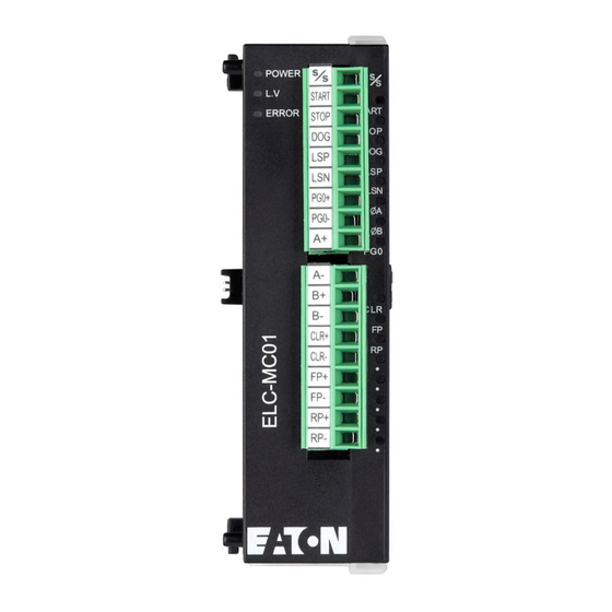
2.2
Product Profile and Outline (LED Indicator and Terminal Block)
6
4
1
25.20
60.00
5
7
POWER
15
s
s
L.V
ERROR
START
STOP
8
DOG
LSP
10
LSN
A
2
B
PG0
16
9
CLR
FP
RP
¡ ´
3
¡ ´
¡ ´
3
¡ ´
¡ ´
3.00
Unit: mm
1.
Status Indicator (Power, L.V. and ERROR)
2.
Model name
3.
DIN rail clip
4.
Terminal
5.
Terminal layout
6.
Mounting hole
7.
Nameplate
8.
Extension port to connect extension module
9.
Extension unit/module clip
10.
DIN rail track (35mm)
11. RS-485 communication port
12.
Clip for combining extension modules
13. Power input
14.
Extension port to connect extension module
15. Upper row terminals
16.
Lower row terminals
2.3
LED Display
POWER : Power indicator, +5V internal power
START : Start input
LV
: Low voltage indicator
STOP : Stop input
lit when external input power is lower than 19.5V
DOG
: DOG (near point signal) input
ERROR : Error indicator (ON/OFF blinking).
FP
: CW pulse output
It will blink when CR#39 is not 0.
RP
: CCW pulse output
ΦA
LSP
: Right limit input indicator
: A-phase input of manual pulse generator
ΦB
LSN
: Left limit input indicator
: B-phase input of manual pulse generator
PG0
: Zero signal input indicator
CLR
: Output clear signal
2.4
Input/Output Terminal
Description
Terminal name
Content
Power input/DC24V (-15~+20%)
Power supply
+24V, 0V
Current consumption 70 10mA; Startup peak current 1.3 A
±
START
Start input terminal
Input
STOP
Stop input terminal
LSP / LSN
Limit Stroke of right/left limit
ΦA+, ΦA-
2007-05-08
ΦB+, ΦB-
PG0+, PG0-
Input
5011641701-MC01
CLR+, CLR-
FP+, FP-
Output
RP+, RP-
Input/Output Circuit
Manual pulse generator
Shielded cable
A-phase
B-phase
Note:
1. Do NOT arrange the wiring of I/O signal wires or power supply in the same wiring duct.
2. Make sure the terminals
cover.
3. Do NOT wire to null terminal
3
3.1
Function Specifications
3.40
Item
Power supply
11
14
Max. number of
connected axes
12
Distance instruction
13
Speed instruction
External output
Upper Row
Lower Row
S/S
A-
START
B+
STOP
B-
External input
DOG
CLR+
LSP
CLR-
LSN
FP+
Pulse output format
PG0+
FP-
Position program & data
PG0-
RP+
transmission
A+
RP-
Connect to EATON ELC
series
3.2
Other Specification
Operation/Storage
Noise Immunity
Grounding
Response
Agency Approvals
-
Vibration/Shock
4ms/12ms
immunity
4ms
1ms
A-phase terminal (+, -) of manual pulse generator input (line driver input)
B-phase terminal (+, -) of manual pulse generator input (line driver input)
Zero signal input terminal +, - (line driver input)
Offers two different functions depending on operation mode.
DOG
(1) It is near-point signal in zero return mode.
(2) It is start signal on interrupt 1st or interrupt 2nd speed mode.
S/S
Signal common terminal of these Inputs (START, STOP, DOG, LSP, LSN)
Clear signal (clear signal of internal error counter for Servo drive)
FP/RP mode: CW pulse output
I/O mode: Output pulse
AB-phase mode: A-phase output
FP/RP mode: CCW pulse output
I/O mode: direction output
AB-phase mode: B-phase output
+24VDC IN
Servo drive
ELC-MC01
START
24V
STOP
0V
LSP
LSN
FP+
DOG
FP-
S/S
RP+
+24V
RP-
ΦA+
CLR+
ΦA-
CLR-
5-24VDC
ΦB+
ΦB-
5-24VDC
PG0+
PG0-
of power module and ELC-MC01 are properly grounded or connects to machine
.
SPECIFICATIONS
Content
DC24V(-15% ~ +20%)
Current consumption 70±10mA; Startup peak current 1.3 A
8 units; (PB/PC/PA/PH series MPU can connect up to 8 extension modules without occupying any I/O.)
Distance value is set by CR.
1. Setting range: -2, 147,483,648~+2,147,483,647; 2. Selectable unit: um, mdeg, 10
0
1
2
3
3. Selectable rate: 10
, 10
, 10
, 10
; 4. Selectable position: absolute and relative position instruction
Speed value is set by CR.
1. Setting range: -2,147,483,648~+2,147,483,647 (conversion value of 10~200KPPS pulse)
2. Selectable unit: pulse/s, cm/min, 10deg/min, inch/min
Photo coupler is for insulation and there are LED indications for all output/input signals.
Outputs: FP and RP (line driver output 5V)
Output: CLR is the type of NPN open collector transistor output (5~24VDC, less than 20mA)
Photo coupler is for insulation and there are LED indications for all output/input signals.
Input point: START, STOP, LSP, LSN, DOG(contact or open collector transistor, 24VDC 10%, 5±1mA)
Inputs: A,
Φ
Φ
B(line driver or open collector transistor, 5~24VDC, 6~15mA)
Input: PG0 (line driver or open collector transistor, 5~24VDC, 6~15mA)
Three selectable modes: Pulse/Dir, FP (CW)/RP (CCW), A/B (all modes are line driver output)
CR data can be read/write via FROM/TO intruction of ELC MPU. The 32-bit data is composed of 2
continuous CR number. The range of 16-bit CR is CR#0 ~ CR#48.
Modules are numbered from 0~7 with 0 closet and 7 farthest to the MPU. Up to 8 modules can be
connected without occupying any digital I/O.
Environmental specifications
℃
℃
1. Operation: 0 ~55 (Temperature), 50~95%(Humidity), pollution degree 2
2. Storage: -25 ~70 (Temperature), 5~95% Humidity
℃
℃
(
)
ESD(IEC 61131-2, IEC 61000-4-2): 8KV Air Discharge
EFT(IEC 61131-2, IEC 61000-4-4): Power Line: 2KV, Digital I/O: 1KV, Analog & Communication I/O: 1KV
RS(IEC 61131-2, IEC 61000-4-3): 26MHz~1GHz, 10V/m
The diameter of the grounding wire cannot be smaller than that of terminals 24V and 0V (if numerous
ELCs are used at the same time, make sure that each ELC is grounded respectively to the ground
poles)
UL508
UL1604, Class1,Div2 Operating temperature code: T5
European community EMC Directive 89/336/EEC and Low Voltage Directive 73/23/EEC
Standard: IEC61131-2, IEC 68-2-6 (TEST Fc)/ IEC61131-2 & IEC 68-2-27 (TEST Ea)
200KHz
4
200KHz
ELC-MC01 Motion control Unit
4ms
CR No.
1ms
Content
HW LW
Address
-
4ms
#0
H'4190
O
R
Model No.
200KHz
#2
#1
H'4191
O
R/W
Pulse rate (A)
#4
#3
H'4193
O
R/W
Feed rate (B)
200KHz
Parameter setting
O
#5
H'4195
R/W
Factory setting:
H'0000
Motor
Combined
b1
b0
Unit
unit
unit
0
0
Motor
pulse
0
1
Machine
pulse
m deg
1
0
pulse
10
Combined
1
1
pulse/sec
pulse/sec
pulse/sec
bit #
When b[6]=0: positive logic. LSP input signal is ON and LPS signal is given.
6
When b[6]=1: negative logic. LSP input signal is OFF and LPS signal is given.
When b[7]=0: positive logic. LSN input signal is ON and LSN signal is given.
7
When b[7]=1: negative logic. LSN input signal is OFF and LSN signal is given.
When b[8]=0: zero return is executed to the direction of CP's decreasing value. When b[8]=1, zero return is executed to the
8
direction of CP's increasing value.
9
When CW running is executed, b[9]=0 is for increasing CP value, but [9]=1 for decreasing.
When b[10]=0: DOG rising-edge is triggered. When b[10]=1,DOG falling-edge is triggered. (available for Interrupt 1st and
10
interrupt 2nd speed position modes)
When b[11]=0: positive logic. When DOG input signal is ON, DOG near point signal is given.
11
When b[11]=1: negative logic. When DOG input signal is OFF, DOG near point signal is given.
12
When b[12]=0: trapezoid acceleration line is chosen. When b[12]=1, S acceleration line is chosen.
13
When b[13]=0: 4ms; when b[13]=1: 12ms(for noise filter).
When b[14]=0: positive logic. When START input signal is ON, START input.
14
When b[14]=1: negative logic When START input signal is OFF, START input.
When b[15]=0: positive logic. When STOP input signal is ON, STOP input.
15
When b[15]=1: negative logic. When STOP input signal is OFF, STOP input.
#7
#6 H'4196
O
R/W
Maximum speed V
#9
#8 H'4198
O
R/W
Bias speed V
bias
-4
inch, Pulse
#11 #10
H'419A
O
R/W
JOG speed V
JOG
Zero return speed
#13 #12
H'419C
O
R/W
V
RT
Zero return
#15 #14
R/W
H'419E
O
deceleration speed
V
CR
The number of PG0
#16 H'41A0
O
R/W
in zero return mode N
±
The number of pulse
#17 H'41A1
O
R/W
in zero return mode P
Zero return mode
#18 H'41A2
O
R/W
H Mode
bit #
0
b[0]=0: normal mode, b[0]=1: override mode
1
b[1]=0: DOG falling-edge detecting is on in zero return mode. b[1]=1: DOG falling-edge detecting is off in zero return mode.
#20 #19 H'41A3 O R/W
Zero point setting (HP)
#21 H'41A5 O R/W
Acceleration time T
acc
#22 H'41A6 O R/W
Deceleration time T
dec
#24 #23 H'41A7 X
R/W
Target position (I) P(I)
#26 #25 H'41A9 X
R/W
Running speed (I) V(I)
#28 #27 H'41AB X
R/W
Target position (II)P(II)
#30 #29 H'41AD X
R/W
Running speed (II) V(II)
.
IL05003023E.pdf
CR (Control Register)
Setting Range
System setting, Read-only (The model number of ELC-MC01 is H'0110.)
Range: 1 ~ +2,147,483,647 PPS/REV, factory setting: 2,000
Pulse/Revolution (PLS/REV)
Range: 1 ~ +2,147,483,647 unit/REV,
Factory setting: 1,000 (unit*1/REV)
b15 b14 b13 b12 b11 b10 b9
b8
b7
b6 b5 b4 b3 b2 b1 b0
Machine
b3 b2
Position rate setting
b5 b4 Pulse output format
unit
0
um
0
0
10
0
0
FP + RP
1
0
1
10
0
1
Pulse + direction
-4
2
inch
1
0
10
1
0
A/B Phase pulse
3
cm/min
1
1
10
1
1
10deg/min
inch/min
Content
Range: 0 ~ +2,147,483,647 unit*1 (10 ~ 200K PPS) *2
max
Factory setting: 200,000 unit*1
Range: 0 ~ +2,147,483,647 unit*1 (0 ~ 200K PPS pulse transfer value) *2
Factory setting: 0 unit*1
Range: 0 ~ +2,147,483,647 unit*1 (10 ~ 200K PPS pulse transfer value) *2
Factory setting: 5,000 unit*1
Range: 0 ~ +2,147,483,647 unit*1 (10 ~ 200K PPS pulse transfer value) *2
Factory setting: 50,000 unit*1
Range: 0 ~ +2,147,483,647 unit*1 (10 ~ 200K PPS pulse transfer value) *2
Factory setting: 1,000 unit*1
Range: 0~+32,767 PLS
Factory setting: 0 PLS
Range: -32,768 ~+32,767 PLS
Factory setting: 0 PLS
b0: Zero return mode, b1: detect DOG falling-edge in zero return mode
Content
Range: 0 ~ ±999,999 unit*1; factory setting: 0 unit*1
Range: 10 ~ +32,767 ms; factory setting: 100 ms
Range: 10 ~ +32,767 ms; factory setting: 100 ms
Range: -2,147,483,648 ~ +2,147,483,647 unit*1 (-2,147,483,648 ~
+2,147,483,647 pulse transfer value) *2; factory setting: 0 unit*1
Range: -2,147,483,648 ~ +2,147,483,647 unit*1 (10 ~ 200K PPS pulse
transfer value) *2; factory setting: 1,000 unit*1
Range: -2,147,483,648 ~ +2,147,483,647 unit*1 (-2,147,483,648 ~
+2,147,483,647 pulse transfer value) *2, factory setting: 0 unit*1
Range: 0 ~ +2,147,483,647 unit*1 (10 ~ 200K PPS pulse transfer value)
*2, factory setting: 2,000 unit*1
Advertisement

Related Manuals for Eaton ELC-MC01


Summary of Contents for Eaton ELC-MC01
- Page 1 ELC-MC01 are properly grounded or connects to machine interrupt 2nd speed position modes) maximum output pulse can be up to 200 KPPS, and built-in various route control modes. The EATON ELC cover. When b[11]=0: positive logic. When DOG input signal is ON, DOG near point signal is given.
- Page 2 IL05003023E.pdf b15 b14 b13 b12 b11 b10 b9 b8 b7 b6 b5 b4 b3 b2 b1 b0 Please refer to “Error Code & Troubleshooting” for detail. Factory setting: Tacc Tdec #39 H’41B7 X Error code Speed Tacc Tdec H’0000 Speed Electronic gearing Vmax Please refer to the following explanation...
Need help?
Do you have a question about the ELC-MC01 and is the answer not in the manual?
Questions and answers