Table of Contents
Advertisement
Quick Links
Advertisement
Table of Contents

Related Manuals for Eaton ELC-COENETM


Summary of Contents for Eaton ELC-COENETM
- Page 1 ELC-COENETM Effective December 2010 Users Manual...
-
Page 3: Table Of Contents
Product Profile and Outline ....................4 Installation and Wiring ......................5 Configuring and applying the ELC-COENETM using ELCSoft (V2.0 or later) ....6 5.1 Connecting the PC to the ELC-COENETM through a LAN ......... 7 5.2 Changing the ELC-COENETM module name and IP address settings...... 9 5.3 Setting up and Clearing a Password ................ - Page 4 ELC-COENETM The companies and products mentioned in this operation manual can be the trade mark possessed by the owner of that trade mark right. For more Information visit: www.eaton.com MN05006001E...
-
Page 5: Introduction
Acting as a server device, the ELC-COENETM provides remote monitoring from SCADA (Supervisor Control and Data Acquisition) software or HMI (Human Machine Interfaces) panels. Acting as a client device, the ELC-COENETM can poll server devices such as VFDs and remote I/O products for use in the ELC control program. -
Page 6: Product Profile And Outline
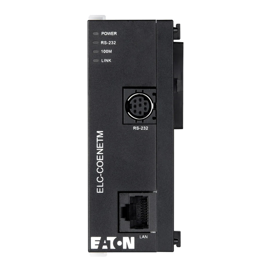
7. Ethernet RJ-45 port 8. DIN rail clip LED indicators Indicator Color Indication POWER Green Power indication RS-232 Communication status for the serial port 100M Orange Network connection status LINK Green Network communication speed For more Information visit: www.eaton.com MN05006001E... -
Page 7: Installation And Wiring
Installation and Wiring How to Connect the ELC-COENETM with the ELC processor Open the extension clips on the left side of the MPU. Connect the extension port of the ELC controller to the ELC-COENETM as shown below. Close the extension clips. -
Page 8: Configuring And Applying The Elc-Coenetm Using Elcsoft (V2.0 Or Later)
ELC-COENETM Installing the ELC-COENETM With Other Extension Modules To connect ELC-COENETM with other extension modules, lift the extension clips of the extension module with a screwdriver and remove the side cover. Connect the second ELC-COENETM as described above. A maximum of 8 left side communication modules are supported. -
Page 9: Connecting The Pc To The Elc-Coenetm Through A Lan
Setting up data exchange to an ELC remote I/O communications adapter (ELC-CAENET) Connecting the PC to the ELC-COENETM through a LAN (1) Connect the PC running ELCSoft and the ELC-COENETM to a common LAN. A direct RJ cable connection can also be used ELC-CONENETM... - Page 10 ELC-COENETM modules (default module name: EATON ELC-COENETM, IP: 192.168.1.5) in the window. (5) Select the ELC-COENETM and double click it to open the setup page. All further ELC-COENETM configuration is done through the setup page For more Information visit: www.eaton.com...
-
Page 11: Changing The Elc-Coenetm Module Name And Ip Address Settings
(1) After you open the setup dialog you will be on the Basic tab. You can modify the module name for easier identification. (2) Next, set up the new IP address for the ELC-COENETM. First switch to “Network” setup page. If there is a DHCP server on the LAN, you may select DHCP in “IP Configuration”. -
Page 12: Setting Up And Clearing A Password
(3) Check “Modify” box and enter “aabb” in “Password” and “Confirm Password" columns. Click on “OK” to save the password. (4) Open the setup page again. The ELC-COENETM is now locked by the password. You For more Information visit: www.eaton.com... -
Page 13: Recovering From A Lost Password
(5) To clear the password, simply leave the password columns blank. Click on “OK” to clear the password. Recovering from a lost password (1) Use ELC-CBPCELC3 cable to connect the PC and ELC-COENETM and open the setup page. Open the “Security” page. MN05006001E... -
Page 14: Setting Ip Filter Protection To Restrict Access
Note: this action returns all parameters are to their default settings. Setting IP Filter Protection to restrict access (1) Follow the steps in: Connecting the PC to the ELC-COENETM through a LAN (2) Open the setup page and switch to the “IP Filter” page. - Page 15 (4) Enter “192.168.0.1” in No. 2 “IP Address” and “255.255.255.0” in the No.2 “Subnet Netmask” column. Click on "OK” to complete the setting. Only the equipment within the IP range can be connected to the ELC-COENETM module. MN05006001E For more Information visit: www.eaton.com...
-
Page 16: Setting Up E-Mail Notification
(4) Check all the events that you want to trigger emails to “Recipient 1”. Click on “OK” to complete the setting. (5) The emails are triggered by writes to the appropriate CRs of the ELC-COENETM module (CR#3-CR#6). After all the settings in ELC-COENETM are completed, enter a program that loads the CR registers based on desired trigger event, compile the ladder diagram and download it to the MPU. -
Page 17: Setting Up Data Exchange Between Elc Processors
K100 K100 Description: If X0 transitions from Off to On, Write “1” into CR#3 of ELC-COENETM, and the first E-Mail will be sent out. If X0 transitions from On to Off. Write “1” into CR#4 of ELC-COENETM, and the second E-Mail will be sent out. - Page 18 ELC-COENETM module is IP address 192.168.1.5. The PC IP address and network mask need to be set up to reside on the same network as the ELC-COENETM. This will allow you to connect to each module using ECISoft on Ethernet. If you choose to use RS232 to configure the Ethernet modules, use the ELC programming cable to connect to each Ethernet module to set the IP address and Subnet Mask.
- Page 19 When complete, the following screen will be displayed: To access the configuration pages for each module, double click its icon. When the icon for the first ELC-COENETM module is double clicked, the following window will open: MN05006001E For more Information visit: www.eaton.com...
- Page 20 120.151.1.4 will only require setting up the IP address, subnet mask and optional gateway address. It will only be receiving messages from the other Ethernet module. Setting up peer-to-peer Ethernet messages in an ELC-COENETM module. From ECISoft, open the Data Exchange tab for the Ethernet module at IP address 120.151.1.2.
- Page 21 PV controller requested by the other Ethernet module and sent in a response message back to the Ethernet module initiating the messages. This Ethernet module will move the data received to the selected D-registers in the PV controller attached to it. The following MN05006001E For more Information visit: www.eaton.com...
- Page 22 When data is placed into D200-D209 in the master controller, it will be sent to D100-D109 in the remote controller. Data in D300-319 in the remote controller will be sent to D50-D69 in the master controller. For more Information visit: www.eaton.com MN05006001E...
-
Page 23: Setting Up Data Exchange From Elc Processor To Any Modbus Tcp Servers
ELC and any Modbus TCP server device. The figure below shows an ELC processor with an ELC-COENETM acting as a Modbus TCP client to an Eaton SVX drive that has an Ethernet OPTCi board installed. The drive is at IP= 196.168.0.197. -
Page 24: Setting Up Data Exchange Between Elc Processor To Other Modbus Tcp Clients
Setting up Data Exchange between ELC processor to other Modbus TCP clients The ELC-COENETM modules can be used for high performance data exchange between any Modbus TCP master and the ELC processors acting as a Modbus TCP server. In the figure below, SCADA software running on the PC acts as a Modbus TCP client to initiate data exchange with the ELC processor. - Page 25 3072~3327 B600~B6FF 3328~3583 B700~B7FF 3584~3839 B800~B8FF 3840~4095 B900~B9FF 0E00~0EC7 003585~003784 000~199 (16-bit) 0E00~0EC7 403585~403784 0EC8~0EFF 003785~003840 200~255 (32-bit) 401793~401903 0700~076F (Odd address valid) MODBUS Device Range Hex Address Address 000~255 1000~10FF 404097~405376 256~511 1100~11FF MN05006001E For more Information visit: www.eaton.com...
- Page 26 436865~440960 6144~6399 9800~98FF 6400~6655 9900~99FF 6656~6911 9A00~9AFF 6912~7167 9B00~9BFF 7168~7423 9C00~9CFF 7424~7679 9D00~9DFF 7680~7935 9E00~9EFF 7936~8191 9F00~9FFF 8192~8447 A000~A0FF A100~A1FF 8448~8703 8704~8959 A200~A2FF 8960~9215 A300~A3FF 440961~443008 9216~9471 A400~A4FF 9472~9727 A500~A5FF 9728~9983 A600~A6FF 9984~9999 A700~A70F For more Information visit: www.eaton.com MN05006001E...
-
Page 27: Setting Up Data Exchange With An Elc Remote I/O Adapter (Elc-Caenet)
5.10 (ELC-CAENET) This application example will demonstrate how to set up an ELC-COENETM Ethernet module to read and write I/O data from an ELC-CAENET Ethernet distributed I/O adapter. The software used to configure the adapter and the COENETM module is called ECISoft and is included in ELCSoft. - Page 28 ELC-COENETM module is IP address 192.168.1.5. The PC IP address and network mask need to be set up to reside on the same network as the ELC-COENETM. This will allow you to immediately connect to each module using ECISoft on Ethernet. If you choose to use RS232 to configure the Ethernet modules, use the ELC programming cable to connect to each Ethernet module to set the IP address and Subnet Mask.
- Page 29 Note the two tabs at the bottom left of the main window. Both modules have been found and each type of module is located in a separate tab. Click the tab for the ELC-CAENET module, then double click its icon to open its configuration pages as follows: MN05006001E For more Information visit: www.eaton.com...
- Page 30 This is also where the IP address can be made static or DHCP. When finished, the Basic tab looks like the following for this example: For more Information visit: www.eaton.com MN05006001E...
- Page 31 Next we need to map the analog I/O data for each of the analog modules connected to the adapter. Each analog module contains many data words. Only those that are absolutely necessary should be mapped. Click the Analog Input/Output Module tab and the following page will be displayed: MN05006001E For more Information visit: www.eaton.com...
- Page 32 Note that 8 input words are mapped along with 4 output words, per the screen below. Note exactly how this data is mapped, it will be needed later when writing the For more Information visit: www.eaton.com MN05006001E...
- Page 33 Click OK to save the configuration and exit this screen. From the main ECISoft screen, click the tab for the ELC-COENETM module, then double click the module’s icon to open its configuration pages. The Overview tab displays specifics about each module.
- Page 34 RX (digital inputs) = 40 bits RY (digital outputs) = 8 bits Read (analog input data) = 8 words Write (analog output data) = 4 words The Remote I/O tab should look like the following: For more Information visit: www.eaton.com MN05006001E...
- Page 35 Note that the data is mapped to addresses in the ELC-PV controller connected the ELC-COENETM module. These addresses may be changed under PLC I/O Mapping in the upper right portion of this page. Enter different starting addresses and the end address will change based on the amount of data for each.
-
Page 36: Cr Definitions For Elc-Coenetm
D100-D109 in the remote controller. Data in D300-319 in the remote controller will be sent to D50-D69 in the master controller. CR Definitions for ELC-COENETM This section contains a description of all CR registers in the ELC-COENETM module. CR No. Type... - Page 37 Reserved Reserved #114 R/W Modbus TCP Time-Out Modbus TCP transaction time-out (ms) #115 R/W Modbus TCP Trigger Set to 1 to send Modbus command. Modbus TCP Status #116 Status of Modbus TCP transaction Register MN05006001E For more Information visit: www.eaton.com...
- Page 38 #250 ~ #220 Reserved Reserved #251 Error Code The ELC-COENETM error code #255 ~ #252 Reserved Reserved Symbol definition: R: Read, W: Write Read and write CR register 1. ELC uses the FROM/DFROM instruction to read CR data of left-side expansion modules.
- Page 39 When the CR is set as “0”, the data have not yet been received. When the CR is set as “1”, the data exchange is in progress. When the CR is set as “2”, the data exchange is successful. When the CR is set as “3”, the data exchange fails. MN05006001E For more Information visit: www.eaton.com...
- Page 40 H’02). See Description on CR#70 and CR#71 for how to set. CR#28: Destination Slave ID When you set up the Slave ID (i.e. K1 ~ K255) for data exchange, ELC-COENETM will automatically search for the corresponding IP address from the Slave IP list. For example, if the ID is set as “0”, the value in CR#25 and CR#26 will be regarded as the...
- Page 41 CR#16: Status of Remote I/O slaves Connection status of Remote I/O polling. CR#16 b0 ~ b3 = 1 when the connection to Remote I/O slave is established. CR#16 b0 ~ b3 = 0 when the connection is closed. MN05006001E For more Information visit: www.eaton.com...
- Page 42 CR#71 for how to set it. CR#119: Modbus TCP Data Length The data length of Modbus TCP in CR#120 ~ CR#247. In 8-bit mode the range is K1 to K100. In 16-bit mode the range is K1 to K200. For more Information visit: www.eaton.com MN05006001E...
- Page 43 Table of error codes: CR#251 Error status Not connected CR#13 is set as 1 but Data Exchange function has not been enabled Connecting to SMTP Server fails DHCP did not acquire correct network parameters MN05006001E For more Information visit: www.eaton.com...
- Page 44 ELC-COENETM MEMO For more Information visit: www.eaton.com MN05006001E...
Need help?
Do you have a question about the ELC-COENETM and is the answer not in the manual?
Questions and answers