Advertisement
Quick Links
Advertisement

Related Manuals for Extech Instruments CLT600


Summary of Contents for Extech Instruments CLT600
- Page 1 Quick Start CLT600 Cable Locator and Tracer...
-
Page 2: Application Illustrations
Application Illustrations Figure 1 Locating wire breaks. Diagram shows one Transmitter in a fixed loca- tion and one Receiver being used in two locations. The Receiver position on the left is detecting a signal, while the Receiver position on the right is not detecting a signal. - Page 3 Figure 3 Two examples of matching connected points in a circuit. #NAS100049; r. AA/70188/70188; en-US...
- Page 4 Figure 4 Two examples of broken line detection tests. Top diagram shows a two-conductor test; bottom diagram shows a single-conductor test. Diagrams show one Transmitter in a fixed location and one Receiver being used in two loca- tions. On the top diagram, the Receiver position on the left is detecting a signal, while the Receiver position on the right is not.
- Page 5 Figure 5 Non-Contact Voltage Detection TR A N SM I TTER C AT I I I 450V Figure 6 Using the supplied earth ground spike (rod) #NAS100049; r. AA/70188/70188; en-US...
- Page 6 Quick Start (English) Note: Please refer to the User Manual for complete instructions: https://support.flir.com. SAFETY • This device has been designed and tested according to CE Safety Requirements for Electronic Measuring Apparatus, EN 61010-1 EN 61326-1 and other safety standards. •...
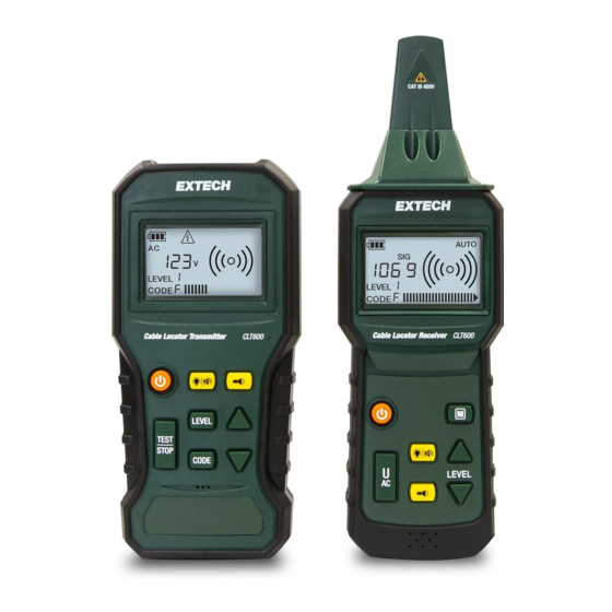
- Page 7 9. Down arrow. Short press to decrement the selection in the LEV- EL or CODE modes. 10. Up arrow. Short press to increment the selection in the LEVEL or CODE modes. 11. Worklight button (short press). 12. Backlight (short press) and beeper mute (long press) button. Receiver Description (shown on right, above) 13.
- Page 8 4. Signal indicator (indicates that the digital display is showing the received signal strength). 5. Manual detection mode. 6. Automatic detection mode. 7. Voltage AC or DC (digital display is showing an AC or DC volt- age measurement). 8. Digital display for voltage measurement (Transmitter) or the Transmitter's output Level as selected by the Transmitter opera- tor.(Receiver).
- Page 9 The Receiver displays SIG (Signal) and the numeric value of the re- ceived signal strength. The optional transmission Code, sent from the Transmitter, is also displayed. Manual Detection Mode Press the M button and select the signal sensitivity level manually (8 steps) using the arrows.
- Page 10 4. Refer to Figure 3 in the Application Illustrations section for examples. Broken Line Detection 1. Method 1: Connect both terminals of the Transmitter, one to each wire, at one end of the line. At the other end of the line, connect the wires together.
- Page 11 TWO-YEAR LIMITED WARRANTY FLIR Systems, Inc. warrants this Extech brand instrument to be free of defects in parts and workmanship for two years from date of ship- ment (a six-month limited warranty applies to sensors and cables). To view the full warranty text please visit: http://www.extech.com/support/warranties.
- Page 12 #NAS100049; r. AA/70188/70188; en-US...
-
Page 14: Quick Start
Quick Start last page Website http://www.flir.com Customer support http://support.flir.com Copyright © 2020, FLIR Systems, Inc. All rights reserved worldwide. Disclaimer Specifications subject to change without further notice. Models and accessories subject to regional market considerations. License procedures may apply. Products described herein may be subject to US Export Regulations. Please refer to exportquestions@flir.com with any questions.
Need help?
Do you have a question about the CLT600 and is the answer not in the manual?
Questions and answers