Table of Contents
Advertisement
Quick Links
Advertisement
Table of Contents

Subscribe to Our Youtube Channel
Related Manuals for Extech Instruments CLT600

Summary of Contents for Extech Instruments CLT600
- Page 1 User Manual CLT600 Cable Locator and Tracer...
-
Page 2: Table Of Contents
Table of contents Introduction................1 Transmitter Features ........... 1 Receiver Features ............1 Common Features ............1 Supplied Materials ............2 Safety ................3 Safety Notes.............. 3 International Safety Symbols ......... 3 Product Description ............4 Transmitter Description ..........4 Receiver Description ........... 6 Display Description ............. - Page 3 Table of contents Maintenance ..............19 Battery Replacement (Transmitter) ....... 19 Battery Replacement (Receiver) ........19 Cleaning and Storage ..........20 Specifications..............21 Transmitter Specifications........... 21 Receiver Specifications..........21 General Specifications..........22 Warranty and Customer Support ......... 23 Two-Year Warranty ............ 23 Calibration and Repair Services........
-
Page 5: Introduction
Introduction Thank you for selecting the Extech CLT600 Cable Locator and Tracer. The system allows you to easily locate cable faults, diagnose and trace cables and circuits, test AC outlet wiring, detect faults in floor heating systems, perform non-contact voltage detection on energized circuits, locate fuses or breakers on panels, and more. -
Page 6: Supplied Materials
Introduction • Battery status indication. 1.4 Supplied Materials This kit includes the following items. • Transmitter and Receiver. • Printed Quick Start. • Test lead set. • Alligator clips (2). • Earth ground rod/spike. • Batteries (12). • Socket adapter with North America 3 pin (type B) plug. •... -
Page 7: Safety
Safety NOTE These devices have been designed and tested according to CE Safety Requirements for Electronic Measuring Apparatus, EN 61010-1 EN 61326-1 and other safety standards. Follow all warnings to ensure safe operation. WARNING Read the safety notes, below, before using this device. 2.1 Safety Notes •... -
Page 8: Product Description
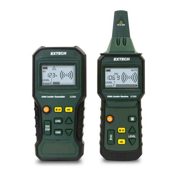
Product Description 3.1 Transmitter Description 1. Negative (COM) terminal This is the ground, or common, terminal. Connect the black test lead to this terminal. 2. Positive ‘+’ terminal Connect the red test lead to this terminal. 3. Worklight 4. LCD Screen 5. - Page 9 Use the arrow buttons to scroll through and select an optional code (F, E, H, d, L, C, O, A). This feature is handy in identifying Transmitters when 2 or more CLT600 systems are used. 9. Down arrow button Short press to increase the signal level in the LEVEL mode or to scroll through the codes in the CODE selection mode.
-
Page 10: Receiver Description
Product Description 3.2 Receiver Description 1. Receiver Antenna Detects and traces a transmitted signal or a voltage source in the non-con- tact detector mode. 2. Worklights 3. LCD 4. Backlight and Mute button Short press to switch the LCD backlight ON or OFF. Long press to switch the beeper ON or OFF. -
Page 11: Display Description
Product Description 8. Down arrow button Short press to decrease the sensitivity level in the Manual signal detection mode. 9. Up arrow button Short press to increase the sensitivity level in the Manual signal detection mode. 10. Manual (M) button Short press to access the Manual signal detection mode. - Page 12 Product Description 11. Signal indicator. Radiating arc graphics appear when Transmitter is send- ing a signal. On the Receiver, the number of arcs corresponds to the re- ceiver 'sensitivity level'. 12. Bar-graph shows signal level. #NAS100035; r. AA/71038/71038; en-US...
-
Page 13: Transmitter Operating Modes
Transmitter Operating Modes 4.1 Transmitter TEST and TRANSMIT Mode When the power is on, the Transmitter defaults to the Test mode. In this mode you can measure AC or DC voltage with the test leads. In this mode you can also transmit a signal. -
Page 14: Receiver Operating Modes
Receiver Operating Modes 5.1 Automatic Detection Mode When the power is on, the Receiver defaults to the auto detection mode where it can trace the high frequency transmission signal at the highest sensi- tivity. The Receiver responds to the detected signal with a variable tone (550 Hz ~ 1.6 kHz) and a bar-graph indication. -
Page 15: Applications
Applications 6.1 Single-pole applications 6.1.1 Locating Opened Wires Figure 6.1 Locating opened wires. Diagram shows one transmitter in a fixed location and one Receiver being used in two locations. The Receiver position on the left is detecting a sig- nal, while the Receiver position on the right is not detecting a signal. 1. - Page 16 Applications Figure 6.2 Locating and Tracing Lines and Receptacles 1. Connect the red, positive (+) terminal to the live (hot) conductor. 2. Connect the black (COM) terminal to earth ground. When working out- doors, you can use the supplied ground spike for an earth ground connection.
-
Page 17: Two-Pole Applications
Applications 6.2 Two-pole Applications 6.2.1 Tracing Connections Figure 6.3 Matching connected points in a circuit. 1. Connect the supplied Socket Adaptor to the Transmitter and plug the AC connector into an AC receptacle. 2. The Transmitter can now measure the voltage of the mains and transmit the signal through the mains. -
Page 18: Broken Line Detection
Applications 6.2.2 Broken Line Detection Figure 6.4 Two Examples of Broken Line Detection (the top diagram shows a two-conductor test, while the bottom diagram shows a single-conductor test). Diagrams show one transmit- ter in a fixed location and one Receiver being used in two locations. On the top diagram, the Receiver position on the left is detecting a signal, while the Receiver position on the right is not detecting a signal. -
Page 19: Other Applications
Applications 6.3 Other Applications 6.3.1 Tracing an Underground Circuit WARNING The circuit under test must not be live. Figure 6.5 Tracing Underground Circuits 1. Connect the Transmitter’s positive (+) terminal as shown in the diagram. 2. The Transmitter’s COM terminal must be correctly connected to earth ground. -
Page 20: Detecting Faults In A Floor Heating System (Using Two Kits)
Applications 6.3.3 Detecting Faults in a Floor Heating System (using two kits) WARNING The circuit under test must not be live. Figure 6.6 Detecting Faults in a Floor Heating System 1. The right end of the circuit is connected to the Transmitter that is sending an ‘x’... -
Page 21: Non-Contact Voltage Detection
Applications 6.3.4 Non-Contact Voltage Detection Figure 6.7 Non-Contact Voltage Detection 1. The circuit under test must be live and connected to the mains. 2. Set the Receiver to the U mode. 3. Hold the tip of the Receiver close to the source of AC voltage to test. 4. -
Page 22: Using The Ground Spike
Applications 6.3.5 Using the Ground Spike TR A N SM I TTER C AT I I I 450V Figure 6.8 Earth Ground Spike 1. Refer to the accompanying diagram. 2. In applications that require an earth ground connection, you can use the supplied ground rod (spike) for convenience. -
Page 23: Maintenance
Maintenance 7.1 Battery Replacement (Transmitter) When the battery symbol appears and flashes on the LCD, replace the bat- teries as follows: Figure 7.1 Replacing Transmitter Batteries • Disconnect the test leads from the Transmitter and switch off the Transmit- ter’s power. •... -
Page 24: Cleaning And Storage
Maintenance • Open the battery compartment by first removing the compartment screw (2) and then removing the cover (1). • Replace the batteries (1.5 V AAA x 6) observing correct polarity (3). • Replace the compartment cover securely before operating the Receiver. 7.3 Cleaning and Storage WARNING To avoid electrical shock or damage to the instrument, do not allow water to access the... -
Page 25: Specifications
Specifications 8.1 Transmitter Specifications Output signal frequency 125 kHz Voltage measurement range 12 ~ 450 V AC / DC Voltage measurement accuracy ± (2% reading + 2 digits) Display Backlit LCD with bar graph Function displays Transmission signal level, Voltage meas- urement (AC / DC), Battery level, Mode (Auto/Manual), and signal Code Power source... -
Page 26: General Specifications
Specifications Dimensions 247(L) × 78 (W) × 45 (D) mm 9.7 (L) x 3.1 (W) x 1.8 (D) inches Weight 11.4 oz. (324 g) with batteries (approximately) 8.3 General Specifications Safety standard compliance EN 61010–1 CAT III 450 V EN 61326–1 Low battery indication Battery symbol appears and flashes on the Work lights... -
Page 27: Warranty And Customer Support
Warranty and Customer Support 9.1 Two-Year Warranty FLIR Systems, Inc. warrants this Extech brand instrument to be free of defects in parts and workmanship for two years from date of shipment (a six-month limited warranty applies to sensors and cables). To view the full warranty text please visit: http://www.extech.com/support/warranties. - Page 28 #NAS100035; r. AA/71038/71038; en-US...
- Page 30 User Manual last page Website http://www.flir.com Customer support http://support.flir.com Copyright © 2020, FLIR Systems, Inc. All rights reserved worldwide. Disclaimer Specifications subject to change without further notice. Models and accessories subject to regional market considerations. License procedures may apply. Products described herein may be subject to US Export Regulations.
Need help?
Do you have a question about the CLT600 and is the answer not in the manual?
Questions and answers