Table of Contents
Advertisement
Quick Links
Advertisement
Table of Contents

Related Manuals for Extech Instruments CO80


Summary of Contents for Extech Instruments CO80
- Page 1 CO80 Combustion Gas Analyzer...
-
Page 2: Table Of Contents
Printing Any Saved Report 4.6.4. Deleting the Last Report 4.6.5. Deleting All Reports 4.6.6. Sending a Report 4.7. Switching Off 4.7.1 In Normal Mode 4.7.2 Power Off In High CO Levels 4.7.3 Power Off During CO Room Test CO80 V3.1 04/06... - Page 3 Gas Leak Detection Calibration and Service Guarantee Appendix A Specifications Instrument Probes Options Gases Draught/Pressure Measurement Appendix B Header Character Set Appendix C Trouble Shooting Guide Appendix D Communicating with a PC Appendix E Setting Up the Printer CO80 V3.1 04/06...
-
Page 4: Introduction
Introduction Thank you for your purchase of the Extech CO80. This instrument has been specifically developed to provide the many functions required by the modern boiler service engineer and to assist with compliance to existing and future legislation. The CO80 now offers five tools in one instrument: 1. -
Page 5: Instrument Overview
Options 2.2.1. Leak Detection Capability This sensor option is fitted inside the instrument, enabling the CO80 to detect flammable gas leaks. Once the gas leak screen has been cleared in order to view other screens and measurements, the thirty second purge period will be to be reactivated in order to perform other gas leak checks. -
Page 6: Front View
Front View Charger Socket Exhaust Cover LCD Display Infrared Window Keypad Gas & Pressure Thermocouple Inlet Ports Sockets CO80 V3.1 04/06... -
Page 7: Back View
Back View Exhaust Cover Calibration Label Infrared Window Barcode Label Thermocouple Gas & Pressure Sockets Inlet Ports CO80 V3.1 04/06... -
Page 8: Keypad
50 sets of combustion analysis and 25 CO room test readings to a PC (see 4.6). Turns the back light on/off and records the pressure for the soundness test and the temperature in the pressure test CO80 V3.1 04/06... -
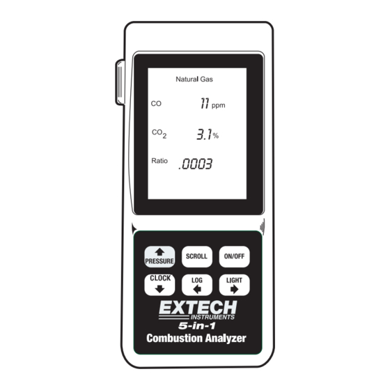
Page 9: Display
Display There are eight standard displays on the CO80, although several of the displays have multiple functions and options. These depend upon the probes connected and menu selected. Display 1 CO in ppm, carbon dioxide in %, and ratio of the 2 gases –... - Page 10 CO in ppm for that minute. Display 8 Provides temperature information. The outlet (flue) temperature is displayed on the top of the screen and the inlet at the bottom, with the difference between the two displayed in the middle. CO80 V3.1 04/06...
-
Page 11: Inlet Ports
The use of these ports is also identified on the information label on the base of the instrument. Pressure (-ve) Pressure (+ve) Gas Sample Port Filter/Water Trap Tubing to CO80 Direction of Screw Cap Filter Sample Flow - Housing Top Displayed on Housing... -
Page 12: Thermocouple Socket (Type-K)
Filters must be used at all times – failure to do so shall invalidate any warranty. Thermocouple Socket (Type-K) The CO80 accepts a standard type-K thermocouple connection for both Inlet and Outlet. -
Page 13: Infrared Window
When on charge, the above symbol will flash only if the instrument has been switched on then off with the charger connected. CO80 V3.1 04/06... -
Page 14: Probe Selection
(flue) at the base of the unit. For pressure measurement, the ports are to be connected using the supplied 5 mm internal diameter silicon tubing to the positive and/or negative ports as required. CO80 V3.1 04/06... -
Page 15: Taking Combustion Readings
Only during the 30 second purge period on power-up can the user alter the fuel, pressure, temperature and communication settings. Should the user wish to use another setting during operation, the power must be recycled and the changes made during the second purge on power-up cycle. CO80 V3.1 04/06... -
Page 16: Fuel Selection
During the power-up purge period, the press and hold “Light” to display the current temperature scale setting. Either “C” or “F” will be displayed. Press and hold “Light” until the required temperature scale is display. Allow the purge period to end to retain settings. CO80 V3.1 04/06... -
Page 17: Printer/Pc Selection
PSI (pounds per square inch) nnG (mm of water column) inG (inches of water column) Release the “Pressure” button when the pressure to be selected is displayed and allow the purge period to end in order to save this setting. CO80 V3.1 04/06... -
Page 18: Flue Readings
‘alarm beeps’ will be heard. The probe should be immediately withdrawn from the flue, and the probe detached from the instrument. The instrument should be run in outside ambient air until CO and CO readings return to zero. CO80 V3.1 04/06... -
Page 19: Reports
4.6. Reports Once a stable set of readings is displayed on the screen of the CO80, the next step is to save (or log) this data to the internal memory in the instrument for future output to a printer, or download to a PC or laptop computer. -
Page 20: Printing The Last Saved Report
Ref. ------------------------------------------- The printer must be turned Flue Gases on with its IR port pointing at ----------------------------------------- the IR port of the CO80 (see Log…………….…………………2 2.10 for additional Date…………..14:53,29/09/2002 information) in order for the Fuel: NATURAL GAS printing to commence. -
Page 21: Printing Any Saved Report
“beep” is heard. The required report will be printed. The printer must be turned on with its IR port pointing at the IR port of the CO80 (see 2.10 for additional information) in order for the printing to commence. -
Page 22: Switching Off
4.7. Switching Off The CO80 has been designed to provide maximum protection to its components by purging the sensors upon shutdown. If the unit is left for 15 minutes, the unit will automatically switch off if the CO reading is below 20 ppm. -
Page 23: Power Off During Co Room Test
Press “Scroll” for “Print” to flash. Press and hold “Log” to send the readings to an IR printer - readings are automatically saved in the memory. Only now can pressing the “On/Off” key turn off the power. CO80 V3.1 04/06... -
Page 24: Other Functions
For pressure readings under 10 mbar, the display has a resolution of two decimal places and for measurements over 10 mbar, the resolution is one decimal place. Depending on the probes connected and the options selected, there are various different pressure readings that can be taken using the CO80 CO80 V3.1 04/06... -
Page 25: Standard Pressure Readings
5.1.1. Standard Pressure Readings Press “Scroll” to select Display 4. Pressing the “Pressure” button once automatically calibrates the CO80 to atmospheric pressure. 5.1.1. Standard Pressure Readings (Cont.) Four bars (----) will initially appear on the display, which will change to 0.00 mbar (or selected pressure scale) once calibrated to atmosphere. -
Page 26: Tightness Test
CO80 to the meter or appliance that requires pressure testing. Press and hold the “Clock” key until the CO80 “beeps” - the counter is now reset to 0 seconds and counting automatically starts in one second intervals. - Page 27 “finish” results are the same The display will alternate between the “P2” and the “dropped” pressure for this part of the test. 5.1.2. Soundness/Tightness Test (Cont.) Display alternates between ”P2” and the “dropped” pressure when single pressure reading is made CO80 V3.1 04/06...
- Page 28 Once the second required pressure reading has been dropped, press and hold “Log” to save the report to memory. If a mistake is made during ------------------------------------------- the tightness test then it can EXTECH INSTRUMENTS. be reset by pressing and 781-890-7740 ------------------------------------------- holding the “Clock” key.
-
Page 29: Pressure And Temperature Readings
– the current value reading is stored at the bottom of the display. The stored value can be overwritten at any time by pressing and holding the “Light” key twice until “beeps” are heard. CO80 V3.1 04/06... -
Page 30: Taking Efficiency Readings
Taking Efficiency Readings CO80 is factory set to calculate gross (G) rather than nett (N) combustion efficiencies. To confirm this, whilst displaying efficiency (see Display 2) hold down the “Light” key and either a G or N will appear in the first position on the efficiency line. -
Page 31: Clock
To change the clock settings, stay in display 6 and press and hold the “Clock” button for approximately 2 seconds. The CO80 will emit a ‘beep’, and the first digit of the time will flash, as will the “Time/Date” icon at the bottom of the display. In this mode, the keys on the keypad have the following alternative functions: •... -
Page 32: Setting Your Security Code
Move down until the first digit of the year flashes, and enter the code ‘7777’ in the year field. This notifies the CO80 that the security code is about to be entered. The first ‘time’ digit will now flash. -
Page 33: Changing A Security Coded Header
Taking Carbon Monoxide Readings The CO80 is able to pin point areas of CO leakage, as well as ambient room levels in accordance to the forthcoming British standard, currently in... - Page 34 CO room test for that appliance at this moment (refer to legislation and/or appliance manufactures instructions). After 30 minutes, the CO80 emits a sound that indicates the required timing period has finished and the maximum CO value in ppm is recorded and displayed.
-
Page 35: Printing The Last Co Report
To print the previous results, refer to 4.6.3. Refer to 4.7.3 to switch off the CO80 during CO room test. 5.5.3 Printing the Last CO Report ress the “Log” key activate the “Save/Print/Send“ menu. Press “Scroll”... -
Page 36: To Delete All Co Room Test Reports
Differential Temperature Measurement The CO80 allows for two thermocouples for differential measurement that is used, for example, to measure the heat loss between the flow and return pipes on a boiler (refer to manufacturers instructions and/or current legislation for the maximum permissible differences between the two). - Page 37 Outlet (Flue) Temperature Difference between Inlet/Out Temperature Inlet Temperature To save, record or print the differential measurements, see Reports in 4.6. CO80 V3.1 04/06...
-
Page 38: 5.7 Gas Leak Detection
Warning Do not subject the CO80 to any flammable gas during the thirty second purge period, as this will affect any future readings until the power is reset. The display will... -
Page 39: Calibration And Service
Extech Instruments official service partner. • Should the serial number on your CO80 be tampered with in any way, then the guarantee will be considered null and void. This guarantee does not affect your statutory rights. -
Page 40: Appendix A Specifications
Accuracy +/- 1°C + 0.3% of reading Hose length 2500mm (9.9’) Options Air/Surface/Liquid Probe Construction: Handgrip with stainless steel shaft, and protective cover K-Type Thermocouple: Accuracy +/- 0.3%, +/- 1°C Temperature range C to +400 C (-58 F to + CO80 V3.1 04/06... -
Page 41: Gases
+/- 0.5% of reading calibration at +50mbar (equivelent to +/- 2.5 mbar) PSI Scale Range -1.4 PSI to +1.4 PSI Resolution 0.001 PSI (0 to +/-1.400 PSI) Accuracy +/- 0.5% of reading calibration at +0.7PSI (equivelent to +/- 0.004 PSI) CO80 V3.1 04/06... -
Page 42: Appendix B Header Character Set
+/- 0.5% of reading calibration at +500 mmWG (equivelent to +/- 2.5 mmWG) Appendix B Header Character Set The following is the list of characters available to include in the printer header (see 5.4): “ & ‘ < > Note: SP denotes a “Space”. CO80 V3.1 04/06... -
Page 43: Appendix C Trouble Shooting Guide
Turn off instrument. “Prob” displayed calibrated whilst Turn back on with probe in flue probe outside flue Continuous alarm Excessive levels Remove probe from sounds of CO flue, and allow unit to run in clean air for 5 minutes CO80 V3.1 04/06... - Page 44 (see connected to a Section 5.1) pressure source Cannot turn High level of Allow unit to run in instrument off carbon clean air until 30 monoxide still second countdown being detected starts by the sensor CO80 V3.1 04/06...
-
Page 45: Appendix D Communicating With A Pc
The CO80 communicates to a PC thru a communications program. The most commonly used program is Hyperterminal which comes standard on any PC equipped with a Windows operating system. Port settings must be set as follows to allow the CO80 to send data streams to the PC. Bits Per Second:... - Page 46 3. Choose a name 4. Select your COM port This setup can be recalled for all future connections. 6. Hang Up Call The PC is now ready to receive Transmissions from the CO80. Choose PORT settings CO80 V3.1 04/06...
-
Page 47: Appendix E Setting Up The Printer
Appendix E Setting Up the Printer The settings on the printer might be different than the settings required for the CO80 to communicate with the Extech 77118I1 printer. Open the paper roll compartment of the printer and locate the dip switch. The switch will be in the bottom of the compartment next to the telephone jack. - Page 48 Warranty EXTECH INSTRUMENTS CORPORATION warrants this instrument to be free of defects in parts and workmanship for two years from date of shipment (a six month limited warranty applies on sensors and cables). If it should become necessary to return the instrument for service during or beyond the warranty period, contact the Customer Service Department at (781) 890-7440 ext.
Need help?
Do you have a question about the CO80 and is the answer not in the manual?
Questions and answers