
Related Manuals for Tektronix TriMode P7500 Series


Summary of Contents for Tektronix TriMode P7500 Series
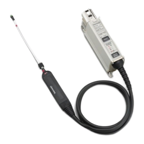
- Page 1 P7500 Series TriMode™ Probes Quick Start User Manual www.tek.com 071-2158-02...
- Page 2 Copyright © Tektronix. All rights reserved. Licensed software products are owned by Tektronix or its subsidiaries or suppliers, and are protected by national copyright laws and international treaty provisions. Tektronix products are covered by U.S. and foreign patents, issued and pending. Information in this publication supersedes that in all previously published material.
- Page 3 Warranty Tektronix warrants that this product will be free from defects in materials and workmanship for a period of one (1) year from the date of shipment. If any such product proves defective during this warranty period, Tektronix, at its option, either will repair the defective product without charge for parts and labor, or will provide a replacement in exchange for the defective product.
-
Page 5: Table Of Contents
Table of Contents Table of Contents General safety summary ........................Environmental Considerations .. - Page 6 Table of Contents Accessories and Options ........................Standard Accessories .
-
Page 7: General Safety Summary
General safety summary General safety summary Review the following safety precautions to avoid injury and prevent damage to this product or any products connected to it. To avoid potential hazards, use this product only as specified. Only qualified personnel should perform service procedures. To avoid fire or personal injury Connect and disconnect properly. - Page 8 General safety summary Terms in this manual These terms may appear in this manual: Warning statements identify conditions or practices that could result in injury or loss of life. WARNING. Caution statements identify conditions or practices that could result in damage to this product or other property. CAUTION.
-
Page 9: Environmental Considerations
The symbol shown below indicates that this product complies with the European Union’s requirements according to Directive 2002/96/EC on waste electrical and electronic equipment (WEEE). For information about recycling options, check the Support/Service section of the Tektronix Web site (www.tektronix.com). Restriction of Hazardous Substances This product has been classified as Monitoring and Control equipment, and is outside the scope of the 2002/95/EC RoHS Directive. -
Page 10: Preface
This manual describes the installation and operation of the P7500 Series TriMode Probes. Basic probe operations and concepts are presented in this manual. All documents listed below are located on the Documentation CD that came with your product. You can also access the Tektronix Web site for these documents (www.tektronix.com/manuals). Documentation... -
Page 11: Key Features
Key Features Key Features The P7500 Series TriMode Probes allow you to take differential, single-ended, and common mode measurements with one probe connection. Key features include: Revolutionary TriMode operation TekConnect Interface Bandwidth (typical) >13 GHz P7513 >16 GHz P7516 >20 GHz P7520 (A – B Mode only; >18 GHz in other modes) Rise time 10-90% (typical) <40 ps P7513... -
Page 12: Operating Considerations
Operating Considerations Operating Considerations Table 1: P7500 Series TriMode Probes Characteristic Description Specification P7513, P7516: ±0.750 V (5X), P7520: ±0.625 V (5X), Input Voltage Dynamic Range ±1.75 V (12.5X) ±1.60 V (12.5X) Input Voltage Range P7513, P7516: +4.0 V, –2.0 V P7520: +3.7 V, –2.0 V (DC + peak AC, Both ranges;... -
Page 13: Installation
Installation Installation Connecting to the Host Instrument NOTE. Your TekConnect instrument may require a firmware upgrade to support full functionality of the P7500 Series probes. Before you connect the probe, check the version requirements. (See page 53, Host Instrument Firmware.) 1. - Page 14 Installation Probe Power-On When the probe is powered on, all LEDs briefly flash as the self-test routine runs, and then the following LEDs remain lit: 5X Attenuation A – B TriMode (Differential) This indicates that the probe is in normal operating mode.
-
Page 15: Connecting Accessories To The Probe Body
Installation Connecting Accessories to the Probe Body CAUTION. The probe has replaceable contacts inside the probe body connector that may stick to the accessory connector when it is disconnected. To prevent damage to the probe, before you connect accessories to the probe body, always check that the contacts are located in the probe body only. - Page 16 Installation 3. Grasp the cable connector by hand and push the cable into the probe body until you feel a click. The cable housing is fully seated when it is flush with the edge of the probe body. 4. To remove the tip, pull the cable tab straight out from the probe body.
-
Page 17: Control Box Controls And Indicators
Installation Control Box Controls and Indicators Atten. Button and LEDs Press the Atten. button to toggle the attenuation setting between 5X and 12.5X. The corresponding LED lights to indicate the selected attenuation. Basic Operation includes more information on selecting the Attenuation and Input Mode. (See page 20, Attenuation and Input Mode Settings.) P7500 Series TriMode Probes Quick Start User Manual... - Page 18 Installation Input Mode Button and LEDs Press the Input Mode button to select one of the four TriMode measurements. The modes cycle in the following sequence: A – B (for differential signal measurement) A – GND (for A input single-ended measurement) B –...
- Page 19 Installation TriMode Probing The TriMode feature allows you to view two single-ended signals and the resultant differential waveform and common-mode voltage without moving the probe connection. Press the Input Mode button to cycle through the waveform views. This example shows a typical HDMI signal (one half-lane) on the A and B inputs.
-
Page 20: Functional Check And Calibration
Test board TriMode DC Calibration board 067-1821-XX Coaxial cable SMA, 50Ω, male-to-male 174-1120-XX Coaxial cable BNC, 50Ω, male-to-male 012-0208-XX Nine-digit part numbers (xxx-xxxx-xx) are Tektronix part numbers Standard accessory included with probe P7500 Series TriMode Probes Quick Start User Manual... - Page 21 Functional Check and Calibration Test Setup 1. Connect the probe to any channel (1–4) of the oscilloscope. 2. Set the oscilloscope to display the channel. 3. Connect an SMA cable from the Probe Compensation or FAST EDGE output connector on the oscilloscope to the SMA connector on the TriMode DC Calibration board.
- Page 22 Functional Check and Calibration Test Procedure 6. Set the probe attenuation to 12.5X and the Input Mode to A-B. 7. Adjust the oscilloscope to display a stable waveform (or press the Autoset button). If you do not see a waveform, check NOTE.
- Page 23 Functional Check and Calibration 9. Cycle the Input Mode button through the remaining selections and compare the displayed waveforms to the waveform that you measured in step 8. A – B (the waveform from step 8) A – GND (same amplitude and polarity as measured in step 8) B –...
-
Page 24: Trimode Probe Calibration
Functional Check and Calibration TriMode Probe Calibration After you perform a functional check of the probe, run a probe calibration routine. We recommend that you repeat the probe calibration for all four of the TriMode settings, and do this on each channel that you use. The probe calibration operation minimizes measurement errors by optimizing the gain and offset of both probe attenuation settings on each channel. - Page 25 Functional Check and Calibration Check the Instrument Calibration Status The Calibration Status of the instrument Signal Path Compensation test must be Pass for the probe calibration routine to run. 1. From the Utilities menu, select Instrument Calibration. 2. In the Calibration box, check that the Status field is Pass.
- Page 26 Functional Check and Calibration Calibrate the Probe 1. Connect the probe to any channel (1–4) of the oscilloscope. Allow the probe to warm up for 20 minutes. 2. Set the oscilloscope to display the channel. 3. Connect a BNC cable from the Probe Calibration output connector on the oscilloscope to the BNC connector on the TriMode DC Calibration board.
- Page 27 Functional Check and Calibration 6. Set the switches on the TriMode DC Calibration board to the positions shown for the selected input mode. (See Table 3.) Table 3: TriMode DC Calibration board switch settings Probe input mode Fast rise/probe cal Gnd/Sig A –...
- Page 28 Functional Check and Calibration 7. In the menu bar, select Vertical and then select Probe Cal. The Probe Setup dialog box appears. (Some oscilloscopes support an automated TriMode calibration routine and switch automatically between input modes as shown below.) 8. Select Clear ProbeCal, and then select Calibrate Probe.
- Page 29 Functional Check and Calibration 10. Oscilloscopes that support the automated TriMode calibration routine will display an on-screen prompt to toggle the Calibration Fixture SIG/GND switch. Follow the instructions to complete the calibration for the remaining input modes. After a successful Probe Cal, Pass appears in the Probe Status box.
-
Page 30: Basic Operation
Basic Operation Basic Operation This section includes more information about using the probe controls on the control box and procedures for connecting the probe to your circuit. Attenuation and Input Mode Settings Atten Selection The ATTEN button toggles the probe between the two nominal attenuation settings of 5X and 12.5X. The choice of attenuation setting is a tradeoff between probe dynamic range and noise. - Page 31 Basic Operation Input Mode Selection The Input Mode button toggles the internal probe input selector switches between the four input mode selections. This TriMode feature allows full characterization of a differential signal from a single soldered connection. A-B Mode. The A-B Mode is used for making differential signal measurements and represents the traditional differential probe functionality.
- Page 32 Basic Operation B-GND Mode. The B-GND mode is used for making probe B input single-ended measurements with TriMode probe tips such as the P75TLRST. The P75TLRST probe tip includes a solder connection for the local circuit ground. In the B-GND Mode the P7500 probe input switch is configured to measure the B input relative to this local circuit ground reference.
-
Page 33: Connecting To A Circuit Board
Basic Operation Connecting to a Circuit Board Use the P75TLRST Long Reach Solder Tip to connect the probe to your circuit. The P75TLRST tip is shipped with the probe and is described below. Other TriMode solder tips are available as optional accessories, as well as a handheld probing module, and are described on the following pages. - Page 34 Basic Operation TriMode Resistor Solder Tips These are optional accessory tips that you can order for your probe. The tips provide solder connection points for the A and B probe input signals at the resistor leads, instead of on the solder tip board.
- Page 35 Basic Operation The dimensions of the solder tip connections are provided here for reference. You can also design the tip footprint into your circuit board layout for easier test connections. To connect the probe tip to your circuit, use the wire and solder that are provided in the wire replacement kit.
- Page 36 Basic Operation Connect the P75TLRST Solder Tip 1. Identify a location where the tip can be placed, soldered, and secured to your circuit. NOTE. You can work with long wires (~1 inch), but keep the finished wire lengths of the signal and ground connections as short as possible.
- Page 37 Basic Operation 4. Attach tip tape to the bottom of the tip. 5. Clean out the tip vias with a solder-wicking material if you are reusing the tip. Thread the wires through the tip. 6. Press the tip to the circuit board and quickly solder the wires to the tip.
- Page 38 Basic Operation Connect the TriMode Resistor Solder Tips Use this procedure to connect both styles of resistor tips to your circuit. 1. Choose a location where the solder tip resistor leads can reach your test points. If you are using a ground connection, note which solder tip ground via is closest to your circuit ground.
- Page 39 Basic Operation 6. Heat the solder tip via and insert the wire. 7. Cut the excess wire on the other side of the solder tip, flush with the board. 8. Cut the ground wire to the length required to reach your circuit ground. Keep the ground wire as short as possible to ensure good performance.
- Page 40 Basic Operation Secure the Tip 11. Push the end of the tip into the probe head until it seats in the probe head. 12. For a secure mechanical connection, use tape or hot glue to secure the tip to your circuit.
- Page 41 Basic Operation Notes on Using the Tips. Use the following precautions when you solder the tips: Use a low-wattage, temperature-controlled soldering iron and a small mass soldering iron tip. The soldering iron temperature should be set as low as possible, while still providing a reliable solder joint. Use SAC305 solder (included with the wire replacement kit) to attach the tip wires to the circuit under test.
- Page 42 Basic Operation P75PDPM Precision Differential Probing Module (Handheld) This is an optional accessory. (See page 44, Optional Accessories.) Assemble the Module 1. Position the module housing as shown. 2. Slide the probing module handle adapter into the module housing. 3. Secure the handle adapter with the thumbscrew.
- Page 43 Basic Operation 4. Insert the probe in the handle adapter. 5. Attach the cable to the probe body. Match the red band to the A input. 6. You can dress the cable in the channels as shown. The front channels are captive and the rear channels are guides.
- Page 44 Basic Operation Adjustments 1. Adjust the tip angle by loosening the setscrew and pivoting the tip. Tighten the setscrew to secure the tip. 2. Adjust the tip spacing by turning the adjustment wheel. The probing module is shipped with a ground spring installed between the tips.
- Page 45 Basic Operation Mounting Features You can mount the probing module to a variety of fixtures and custom probing arms, using the features described below: 1. The barrel at the rear of the P75PDPM fits into the end of the PPM203B probe holder. 2.
-
Page 46: Connecting The Probe To Instruments Without A Tekconnect Interface
The 80A03 TekConnect Probe Interface adapts any TekConnect probe to the TDS8X00, CSA8X00, and DSA8200 Series oscilloscopes. The RTPA2A TekConnect Probe Interface adapts any TekConnect probe to Tektronix Real-Time Spectrum Analyzers. NOTE. The 80A03 and RTPA2A interfaces are limited to a pass-through bandwidth of 12 GHz. -
Page 47: Probe Applications
Probe Applications Probe Applications The following applications show how the P7500 Series probe characteristics enable measurements with good signal fidelity. Measuring a PCI Express Signal with a P7500 Series Probe and RT-Eye Application Software When the P7500 Series probe is used with a TDS6000 or TDS70000 real-time oscilloscope configured with RT-Eye application software, physical layer testing on PCI Express signals is... -
Page 48: Accessories And Options
Accessories and Options Accessories and Options You can reorder the following replacement parts and accessories. Note that in some cases, the reorder quantities may differ from those that ship with the probe. Standard Accessories The following accessories are shipped with the P7500 Series probes. If no quantity is listed, only one of that item is shipped. Reorder part number Accessory and quantity... - Page 49 Accessories and Options Reorder part number Accessory and quantity Description Calibration Certificate. A certificate of traceable calibration is provided with every probe. Data Calibration Report. The Data Calibration Report lists the manufacturing test results of your probe at the time of shipment and is included with every probe.
- Page 50 Accessories and Options Reorder part number Accessory and quantity Description 067-1821-XX TriMode DC Calibration Fixture. Use this fixture to perform a functional check and a DC calibration with the host instrument. 174-1120-XX 50 Ω SMA-M to SMA-M cable assembly, 8.5 in. To perform a functional check, use this cable to connect the DC Calibration fixture to the Fast Rise Time output connector on the host instrument.
- Page 51 Accessories and Options Reorder part number Accessory and quantity Description 020-2729-XX Accessory Kit. The kit includes an assortment of accessories that are described below. A reference sheet is included as a quick guide for using and reordering the probe accessories in the kit.
- Page 52 Accessories and Options Reorder part number Accessory and quantity Description 006-8237-XX Adhesive Tip Tape. Use the double-sided adhesive tip tape (Strip of 10) to secure the solder tip assembly to your circuit board. 016-0633-XX Color Band Kit. This kit includes two sets of five colored pairs.
- Page 53 Accessories and Options Reorder part number Accessory and quantity Description 013-0359-XX Replacement Bullet Contacts. To maintain the best signal (Package of 4) integrity, replace the bullets in the probe body after 200 insertion cycles. 003-1896-XX Bullet Removal Tool. This tool allows you to safely remove and install the bullet contacts.
-
Page 54: Optional Accessories
Accessories and Options Optional Accessories Optional accessory Part number Description 020-2936-XX TriMode Resistor Solder Tip Kit. This tip provides solder connection points at 100 Ω resistors that extend about 0.2 in (5 mm) from the solder tip board. The resistors can withstand more solder cycles than the standard P75TLRST solder tip, and can be replaced if they break. - Page 55 Accessories and Options Optional accessory Part number Description 020-2937-XX Replacement Resistor Kit for TriMode Solder Tips. This kit includes: 100 Ω leaded resistors, quantity 50 75 Ω surface-mount, 0402 resistors, quantity 50 Nonconductive tubing, quantity 50 P75PDPM Probing Module Kit. This kit allows you to browse multiple test points in your circuit without using a soldered connection.
- Page 56 Accessories and Options P75PDPM kit contents Part number Description Order P75PDPM kit Probing Module. The Probing Module includes the P7500 Tip Cable and a large ground spring pre-attached to the tip pair, ready to connect to your probe. To order the Probing Module, order the P75PDPM kit.
- Page 57 Accessories and Options P75PDPM kit contents Part number Description 367-0545-XX Probing Module Handle Adapter. The Handle Adapter connects the probe body to the handheld probing module. 016-1998-XX Ground Spring Kit, Large. (Package of 4) The handheld probing module requires a spring to make a ground connection between the ends of the two input tips.
- Page 58 Accessories and Options P75PDPM kit contents Part number Description 003-1900-XX Ground Spring Tool. This tool simplifies spring removal and installation. The ends of the tool match the two springs that mount between the probe tips. A tab in the center of the tool is used to set the span of the tips to the optimum width for spring replacement.
- Page 59 Accessories and Options Optional accessory Part number Description 067-1586-XX Deskew Fixture. Use this fixture to time-align the probe to other probes connected to your measurement system. PPM203B PPM203B Articulating Arm. This high-precision articulating arm has fine adjustment controls for all three axes. It is designed for probing circuit boards, hybrids, and multi-chip modules (MCMs), that employ fine-pitch devices and interconnects.
- Page 60 Accessories and Options Optional accessory Part number Description PPM100 PPM100 Probe Positioner. This general-purpose benchtop probe holder with flexible arm is designed for hands-free probing that requires adjustable fine positioning. The heavy duty base can be replaced with the clamp for securing the probe arm in a variety of situations.
- Page 61 Accessories and Options Optional accessory Part number Description 80A03 80A03 TekConnect Probe Interface Module. Use this module with 80E0X Sampling Modules to adapt TekConnect probes to CSA8200 and TDS8200 Series Sampling Oscilloscopes. NOTE. The 80A03 interface is limited to 12 GHz pass-through bandwidth.
-
Page 62: Options
Accessories and Options Options Option CA1. A single calibration event, or coverage for the designated calibration interval, whichever comes first Option C3. Calibration Service 3 years Option C5. Calibration Service 5 years Option D1. Calibration Data Report-ships standard with probe Option D3. -
Page 63: Maintenance
To check the firmware version on Windows-based instruments, from the menu bar, click Help/About TekScope. On Linux-based instruments, press the Utilities button on the front panel. If you need to upgrade your instrument firmware, go to www.tektronix.com/software to download the latest firmware. P7500 Series TriMode Probes Quick Start User Manual... -
Page 64: Error Conditions
If one of the Range or TriMode LEDs does not remain lit after you connect the probe, an internal probe diagnostic fault exists. Disconnect and reconnect the probe to restart the power-on diagnostic sequence. If the symptoms continue, the probe is defective, and must be returned to Tektronix for repair. Signal Display If the probe is connected to an active signal source and you do not see the signal displayed on the oscilloscope: Check the probe tip connection on your circuit. - Page 65 Maintenance Input Mode Selection If you cannot select an Input Mode other than A-B and you are using a TriMode tip that does not provide a circuit ground connection (such as the P75PDPM handheld module), this is normal operation. The other input modes refer to circuit ground and are only valid when a TriMode tip that provides a circuit ground connection is selected.
-
Page 66: User-Replaceable Parts
Maintenance User-Replaceable Parts This section describes the probe components that are replaceable due to normal wear. Bullet Contacts The input sockets in the probe body assembly are protected by replaceable bullet contacts. (Replaceable bullets are included in the accessory kit.) The bullet contacts protect the input sockets by absorbing the wear from repeated connect/disconnect cycles of the accessory... - Page 67 Maintenance Removing the Bullets Follow these steps to remove the bullets by using the removal tool: 1. Squeeze the tool plunger to extend the holder tangs. 2. Insert the tool into the probe body so that the holder tangs surround one of the bullets.
- Page 68 Maintenance Inspecting the Bullets and Connectors Use a microscope to closely examine the bullets and connectors. Use the illustrations to determine if the contacts appear worn or broken, and always replace them in pairs. 1. Good 2. Chipped or bent ground contacts (outer conductor) 3.
- Page 69 Maintenance Installing the Bullets 1. Squeeze the tool plunger to extend the holder tangs. 2. Insert a new bullet into the tool so that the holder tangs surround the bullet. 3. Release the plunger to secure the holder tangs on the bullet. 4.
- Page 70 Maintenance Replacing the TriMode Solder Tip Resistors The resistors that are presoldered to the tips can break off during normal use. A kit of replacement resistors is available. (See page 44, Optional Accessories.) To replace the resistors, do the following: 1.
- Page 71 Maintenance 4. If you are replacing the resistor on the extended resistor tip, slide a piece of tubing included with the resistor kit over the lead. This will insulate the resistor lead. 5. Heat the solder in the via and insert the resistor lead into the via: until the insulating tube comes into contact with the tip board, if you are replacing the...
-
Page 72: Handling The Probe
Maintenance Handling the Probe This probe is a precision high-frequency device; exercise care when you use and store the probe. The probe and cable are susceptible to damage caused by careless use. Always handle the probe at the control box and probe body to avoid undue physical strain to the probe cable, such as kinking, excessive bending, or pulling. -
Page 73: Cleaning The Probe
Maintenance Cleaning the Probe CAUTION. To prevent damage to the probe, do not expose it to sprays, liquids, or solvents. Avoid getting moisture inside the probe during exterior cleaning. Do not use chemical cleaning agents; they may damage the probe. Avoid using chemicals that contain benzine, benzene, toluene, xylene, acetone, or similar solvents. -
Page 74: Returning The Probe For Servicing
Maintenance Returning the Probe for Servicing If your probe requires servicing, you must return it to Tektronix. If the original packaging is unfit for use or not available, use the following packaging guidelines: Preparation for Shipment 1. Use a corrugated cardboard shipping... -
Page 75: Index
Index Index Connecting to circuit with handheld module, 32, 33 Accessories Firmware, 53 solder tip, 23 optional, 44 Functional check, 10 Connecting to instruments standard, 38 with a TekConnect interface, 3 Adjustments, 34 without a TekConnect Handling the probe, 62 interface, 36 Host instrument firmware, 53 Controls and indicators... - Page 76 Index connecting, 26 See also Demo video on Probe Related documentation, vi applications, 37 Replaceable parts Solder Tip Resistors, 45 calibrating, 16 bullet contacts, 56 Standard accessories, 38 cleaning, 63 solder tip resistors, 60 handling, 62 Returning the probe, 64 Probe controls Atten button and LEDs, 7, 20 TriMode Solder Tip...
Need help?
Do you have a question about the TriMode P7500 Series and is the answer not in the manual?
Questions and answers