Table of Contents
Advertisement
Quick Links
Advertisement
Table of Contents

Related Manuals for Tektronix CT-6


Summary of Contents for Tektronix CT-6
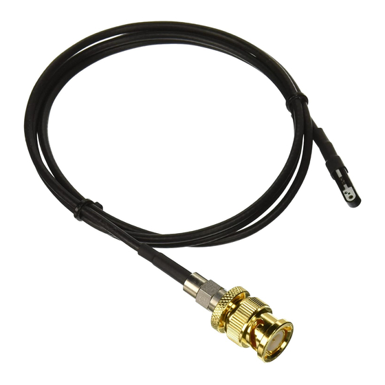
- Page 1 Instruction Manual CT-6 High Frequency AC Current Probe 071-0453-00...
- Page 2 Copyright © Tektronix, Inc. All rights reserved. Tektronix products are covered by U.S. and foreign patents, issued and pending. Information in this publication supercedes that in all previously published material. Specifications and price change privileges reserved. Tektronix Inc., P.O. Box 500, Beaverton, OR. 97077...
- Page 3 Tektronix, with shipping charges prepaid. Tektronix shall pay for the return of the product to Customer if the shipment is to a location within the country in which the Tektronix service center is located. Customer shall be responsible for paying all shipping charges, duties, taxes, and any other charges for products returned to any other locations.
-
Page 5: Table Of Contents
....CT-6 Test Record ........ - Page 6 Verify Frequency Response and Sensitivity ... . CT-6 Test Record – Alternate Procedure ....
- Page 7 Figure 4: Using a square pin and jumper ....Figure 5: Securing the CT-6 probe head to a test fixture board ......... .
- Page 8 Table of Contents CT-6 Instruction Manual...
-
Page 9: General Safety Summary
Do Not Operate With Suspected Failures. If you suspect there is damage to this product, have it inspected by qualified service personnel. Do Not Operate in Wet/Damp Conditions. Do Not Operate in an Explosive Atmosphere. Keep Product Surfaces Clean and Dry. CT-6 Instruction Manual... - Page 10 WARNING indicates an injury hazard not immediately accessible as you read the marking. CAUTION indicates a hazard to property including the product. Symbols on the Product. These symbols may appear on the product: Double Protective Ground CAUTION Insulated Refer to Manual (Earth) Terminal CT-6 Instruction Manual...
-
Page 11: Contacting Tektronix
1-800-TEK-WIDE (1-800-835-9433 ext. 2400) 6:00 a.m. – 5:00 p.m. Pacific time Or contact us by e-mail: tm_app_supp@tektronix.com For product support outside of North America, contact your local Tektronix distributor or sales office. Service Contact your local Tektronix distributor or sales Support office. - Page 12 Contacting Tektronix CT-6 Instruction Manual viii...
-
Page 13: Getting Started
Getting Started The CT-6 is a miniature AC current probe suited for probing low-voltage, high-frequency circuits. Performance highlights include the following: H 250 kHz to 2 GHz typical bandwidth H 5 mV/mA sensitivity H low insertion impedance H inductive pick up or injection of signals For a complete list of specifications, see page 21. -
Page 14: Accessories And Options
H Marker bands for identifying multiple probes on the inputs of a test instrument (016-1315-00) H Certificate of traceable calibration Options The following CT-6 options are available at the time of purchase: H Option C3 (three years calibration services) H Option D1 (calibration data) H Option D3 (three years calibration data) -
Page 15: Installation
Install the probe on the measurement instrument and in the circuit as detailed in this section. To measure or inject a signal using the CT-6 current probe, do these steps: 1. Connect the SMA output connector of the CT-6 current probe to the measurement instrument, or to the signal generator if injecting a signal. - Page 16 7. Power on the circuit under test and measure or inject the signal. Stay within the ratings of the probe. For information on the ratings of the probe and on how to optimize performance, refer to Operating Basics on page 9 and Specifications on page 21. CT-6 Instruction Manual...
-
Page 17: Figure 2: Using A Single Wire
Getting Started Observe polarity of circuit, use short wire, keep probe head close to the circuit board Polarity dot Position probe head to optimize signal fidelity Figure 2: Using a single wire CT-6 Instruction Manual... -
Page 18: Figure 3: Using Two Wires To Measure Differential
Transformer wire, 26 gauge or smaller Figure 3: Using two wires to measure differential current Jumper Polarity dot NOTE: This type of connection is not suitable for frequencies above 1 GHz. Figure 4: Using a square pin and jumper CT-6 Instruction Manual... -
Page 19: Probe Holder
Probe holder Horizontal Vertical Figure 5: Securing the CT-6 probe head to a test fixture board To mount the probe holder, do these steps: 1. Temporarily place the probe and probe holder in the position you intend to mount them. -
Page 20: Evaluation Board (Optional)
Evaluation Board (Optional) Prepare the optional evaluation board for use by installing the five rubber feet with the screws provided; install one foot at each corner of the board and one in the middle. CT-6 Instruction Manual... -
Page 21: Operating Basics
Operating Basics For accurate measurements, it is important to understand the electrical characteristics of the CT-6 current probe and how these characteristics affect the way you use the probe. The following topics are discussed in this section: H Interpreting Current and Voltage Ratings... -
Page 22: Matching Impedances
Even though the current probe can measure signals from (or inject signals to) circuits with varying impedances, the ideal impedance match is 50 W. Improperly matched impedances can cause aberrations and affect the probe sensitivity. CT-6 Instruction Manual... -
Page 23: Measuring Current
To calculate the current in the circuit, divide the units of voltage measured on the probe output by 5. For example, if you measure a 50 MHz signal that is 200 mV , the actual current in the circuit is 200 B 5 = 40 mA CT-6 Instruction Manual... -
Page 24: Injecting Current Signals
30 5 = 150 mV WARNING. To avoid personal injury, use the probe on grounded systems only. To avoid RF burn hazard, apply stimulus signal only after connecting the probe to the circuit. CT-6 Instruction Manual... -
Page 25: Optimizing Performance At High Frequencies
Operating Basics Optimizing Performance at High Frequencies The CT-6 current probe preserves the fidelity of the signal without the effects caused by the resistive elements of conventional passive probes. This is because the current probe couples signals magnetical- ly rather than electrically to the measurement instrument or from the signal source. -
Page 26: Selecting The Wire Size And Length
(approximately 20 to 25 gauge). When measuring high-frequency signals with larger diameter wire, it is generally best to position the probe head perpendicular to the circuit board under test. See Figure 9. CT-6 Instruction Manual... -
Page 27: Figure 9: Positioning For Best Hf Response
Operating Basics Figure 9: Positioning for best HF response (20–25 gauge) CT-6 Instruction Manual... -
Page 28: Ground Side And Signal Side Measurements
Ground Side Figure 10: Coupling the probe to signal side or ground side The optional evaluation board has separate signal side and ground side connections to help assess the effects of these two techniques on signal measurements. CT-6 Instruction Manual... -
Page 29: Using The Optional Evaluation Board
Operating Basics Using the Optional Evaluation Board The evaluation board for the CT-6 current probe (Figure 11) is available as a purchase option or optional accessory. This fixture simplifies testing the probe for purposes of characterization or verification. Figure 11: Test Fixture board for the CT-6 current probe... -
Page 30: Calibration Lines
Figure 12 demonstrates how to use a probe holder to secure the probe in two different ways. The holder uses two 2-56 screws in .080 inch diameter holes spaced 0.360 inches apart center to center. CT-6 Instruction Manual... -
Page 31: Figure 12: Securing The Ct-6 Probe Head To The Test
Operating Basics Probe holder Horizontal Vertical Figure 12: Securing the CT-6 probe head to the test fixture board CT-6 Instruction Manual... - Page 32 Operating Basics CT-6 Instruction Manual...
-
Page 33: Specifications
Specifications Tables 1 and 2 list the specifications for the CT-6 current probe. All specifications are guaranteed unless noted as “typical.” Typical specifications are provided for your convenience but are not guaranteed. Specifications marked with the n symbol have corresponding checks in the Performance Verification section on page 25. -
Page 34: Figure 13: Typical Frequency Response (Bode Plot)
Specifications –17 –20 –23 –26 –29 –32 –35 –38 –41 100k 100M Figure 13: Typical frequency response (Bode plot) –10 –20 100k 100M Figure 14: Typical group delay (df/df) CT-6 Instruction Manual... - Page 35 17 g, stand alone 322 g , when packaged for domestic shipment 381 g, when packaged for domestic shipment with Option TF Probe head (case) dimensions Height: 4.3 mm Width: 4.3 mm Depth: 17.8 mm Cable length CT-6 Instruction Manual...
- Page 36 Specifications CT-6 Instruction Manual...
-
Page 37: Performance Verification
Performance Verification Use the procedures in this section to verify the performance of the CT-6 current probe to the following warranted specifications: H Sensitivity H Frequency Response Before beginning these procedures, photocopy the test record on page 29 (or page 33 if using a network analyzer) and use it to record test results. -
Page 38: Preparation
5. Secure the probe holder to the board with two 2–56 screws. 6. Carefully solder the bare wire to the evaluation board. Face Polarity dot to this side Load Signal source Figure 15: Securing the current probe to the evaluation board CT-6 Instruction Manual... -
Page 39: Frequency Response And Sensitivity
Measure Output and Calculate Sensitivity 1. Connect the SMA output of the CT-6 current probe to the signal input of the digital oscilloscope. 2. Connect the output of the signal generator to the SMA connector on the evaluation board. -
Page 40: Measure High End Frequency Response
4. Measure the the output of the signal generator on the oscilloscope and save or record the value. 5. Connect the SMA output of the CT-6 current probe to the signal input of the digital oscilloscope. 6. Connect the output of the signal generator to the SMA connector on the evaluation board. -
Page 41: Ct-6 Test Record
Performance Verification CT-6 Test Record Identification Number Procedure performed by Date Test Tests Low limit Result High limit Sensitivity @ 50 MHz –20.27 dB –19.73 dB Frequency @250 kHz –3 dB response @1.5 GHz –3 dB CT-6 Instruction Manual... -
Page 42: Frequency Response And Sensitivity - Alternate Procedure
3. Set frequency to log scale if desired. 4. Set for 3.5 mm diameter cables and select full two-port operation. 5. Connect one SMA cable to Port 1 of the network analyzer and the other cable to Port 2. CT-6 Instruction Manual... -
Page 43: Calibrate Network Analyzer With Evaluation Board
Port 1, and then repeat for Port 2. 4. Connect Port 1 and Port 2 to the feedthrough line and check for a flat line. 5. Move zero reference to about 3 divisions from the top graticule line. 6. Save the file. CT-6 Instruction Manual... -
Page 44: Verify Frequency Response And Sensitivity
7. Note the frequencies measured at the – 3 dB points at the high and low frequencies and record them on the test record. 8. Record the sensitivity (in dB) at 50 MHz on the test record. CT-6 Instruction Manual... -
Page 45: Ct-6 Test Record - Alternate Procedure
Performance Verification CT-6 Test Record – Alternate Procedure Identification Number Procedure performed by Date Tests Low limit Test Result High limit Frequency low frequency < 250 kHz 250 kHz response high frequency 1.5 GHz > 1.5 GHz (–3 dB point) - Page 46 Performance Verification CT-6 Instruction Manual...
Need help?
Do you have a question about the CT-6 and is the answer not in the manual?
Questions and answers