Advertisement
Quick Links
xx
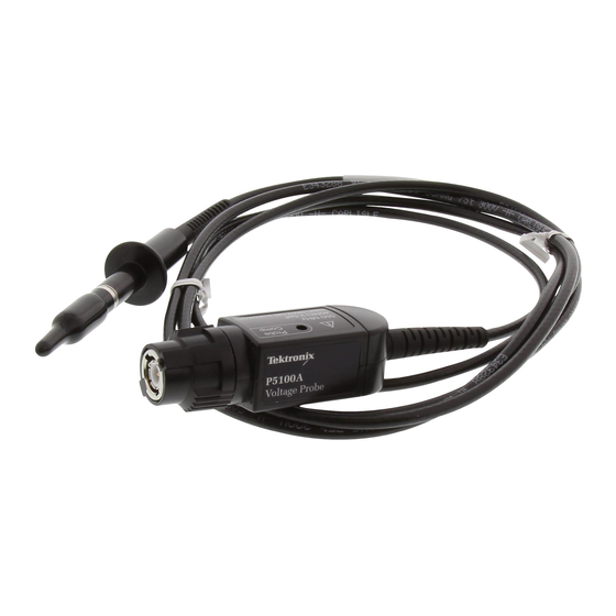
P5100A
500 MHz 100X High Voltage Probe
Instructions
* P071288200*
x
071-2882-00
Operating Information
The P5100A Probe is a high impedance probe with
100X attenuation that is designed for use with Tektronix
ground-referenced oscilloscopes.
Connect the probe as shown in the illustrations below.
Compensating the Probe
Due to variations in oscilloscope input characteristics,
the low-frequency compensation of the probe may need
adjustment after you move the probe from one oscilloscope
channel to another.
1.
Connect the probe to the oscilloscope channel that you
plan to use for your measurements.
2.
Connect the probe to the probe compensation output
terminals on the oscilloscope front panel.
WARNING.
To avoid electric shock, only connect to the
Probe Comp signal on the oscilloscope when making
this adjustment. To avoid electric shock, only use the
insulated adjustment tool when making compensation
adjustments.
3.
Push AUTOSET or otherwise adjust your oscilloscope
to display a stable waveform.
4.
Adjust the trimmer in the probe until you see a perfectly
flat-top square wave on the display. (See illustration.)
Standard Accessories
The probe includes the accessories shown below.
WARNING.
To avoid electric shock when using the probe
or accessories, keep your fingers behind the finger
guard of the probe body and away from the shaded area
shown in the accessory illustrations below.
Item
Description
Small hook tip (TASH)
Use this tip to access test
points in tight spaces. Screw
the hook tip onto the probe tip
and then clamp the hook onto
the circuit.
Rating: 2300 V CAT I
1000 V CAT II
Reorder Tektronix part number
013-0386-xx
Large hook tip (TALH)
Screw the hook tip onto the
probe tip and then clamp the
hook onto the circuit.
Rating: 2300 V CAT I
1000 V CAT II
Reorder Tektronix part number
013-0384-xx
Ground lead (TAGL)
Slide the ground lead over the
probe head and snap it into
place.
Connect the banana plug
end directly to your circuit
ground, or use the crocodile
clip included with the probe.
Reorder Tektronix part
numbers:
6 inch: 196-3524-xx
18 inch: 196-3525-xx
Item
Description
Crocodile clip
Attach the clip to the banana
end of the ground lead and
then to your circuit ground.
Reorder Tektronix part number
344-0461-xx
Ground spring
Use this to limit aberrations on
high frequency signals caused
by ground path inductance.
You can bend the spring
to reach nearby ground
connections (within ~1 in).
Reorder Tektronix part number
214-5298-xx
Color bands
Use these bands to identify
the oscilloscope channel at the
probe head.
Reorder Tektronix part number
016-1886-xx (5 pairs)
Adjustment tool
Use only this insulated tool for
compensation adjustments.
Reorder Tektronix part number
003-1433-xx
Optional Accessories
The accessories shown below are available for the probe
and are rated ≤30 V unless indicated otherwise.
Part
Accessory
number
013-0291-xx
BNC to Tip Adapter,
Unterminated
Rubber Spring Tip
206-0060-xx
Advertisement

Related Manuals for Tektronix P5100A


Summary of Contents for Tektronix P5100A
- Page 1 Operating Information Standard Accessories Item Description The P5100A Probe is a high impedance probe with The probe includes the accessories shown below. Crocodile clip 100X attenuation that is designed for use with Tektronix Attach the clip to the banana WARNING.
- Page 2 Covers. Do not touch exposed connections and components Performance verification and adjustment procedures Additional IEC61010-031; IEC 61010-031/A1:2008 when power is present. are available on the Tektronix Web site. Go to Safety www.tektronix.com/manuals and enter P5100A in the Standards Inspect The Probe and Accessories. Before each use, search field.
Need help?
Do you have a question about the P5100A and is the answer not in the manual?
Questions and answers