
Related Manuals for Tektronix GeoProbe G10


Summary of Contents for Tektronix GeoProbe G10
- Page 1 G10 Hardware Maintenance Guide Software Version 7.13.2 ® GeoProbe Tektronix Communications | For Licensed Users | Unauthorized Duplication and Distribution Prohibited...
- Page 2 Copyright © Tektronix, Inc. All rights reserved. Printed in the USA. Tektronix products are covered by U.S. and foreign patents, issued and pending. Information in this publication supersedes that in all previously published material. Specification and price change privileges reserved. TEKTRONIX and TEK are registered trademarks of Tektronix, Inc.
-
Page 3: What's New In G10 Hardware Version 7.13.2
ERSION Feature ID Description Refer to: F-02470 New Applications Blade Chapter G10 Probe G10 probes support a new IAP320 application blade. Configurations Chapter Blades and RTMs Rev. 002-140228 Tektronix Communications | For Licensed Users | Unauthorized Duplication and Distribution Prohibited... -
Page 4: Table Of Contents
DC PEMs ......................26 Front Panel LEDs................... 27 AC PEMs ......................28 Front Panel LEDs................... 28 Fan Trays........................29 Electro-Static Discharge Points................... 30 G10 Hardware Maintenance Guide 7.13.2 Tektronix Communications | For Licensed Users | Unauthorized Duplication and Distribution Prohibited... - Page 5 SA100R, SA100J, SA200R, and SA200J Front Panel ...........77 SA210J Front Panel ....................77 Front Panel LEDs ....................78 Disk Enclosure Rear Panel...................79 SA200R Controller Enclosure Rear Panel ..............79 G10 Hardware Maintenance Guide 7.13.2 Tektronix Communications | For Licensed Users | Unauthorized Duplication and Distribution Prohibited...
- Page 6 Storage Array Maintenance Guidelines ..............125 Replacing a Power Supply ..................126 Removing the Power Supply.................126 Installing the Power Supply................128 Bezel (Air Filter) Procedures.................129 G10 Hardware Maintenance Guide 7.13.2 Tektronix Communications | For Licensed Users | Unauthorized Duplication and Distribution Prohibited...
- Page 7 FP100 Fuse Panel ..................151 G10 Equipment Warning Labels ................153 Appendix A SFP Reference ........................154 Monitored Ports SFPs ....................154 1 Gb Port SFPs ......................155 1000base-LX Fiber....................155 G10 Hardware Maintenance Guide 7.13.2 Tektronix Communications | For Licensed Users | Unauthorized Duplication and Distribution Prohibited...
- Page 8 10Gbase-LR Fiber....................158 Minimum Signal Levels ....................158 Installing SFPs ......................159 IIC200 ......................160 IIC100 ......................161 TRM100 RTM....................161 PRM200 RTM or PRM300 RTM ..............162 SRM200 RTM....................162 G10 Hardware Maintenance Guide 7.13.2 Tektronix Communications | For Licensed Users | Unauthorized Duplication and Distribution Prohibited...
-
Page 9: Chapter 1 G10 Probe Overview
IP interfaces with a distributed architecture optimized to handle larger traffic volumes. With native IPv4 and IPv6 support, the GeoProbe G10 offers the following benefits: Optimized for portions of the operator networks with high volumes of voice and data ... -
Page 10: G10 Probe Configurations
TWO 10G physical ports available to monitor traffic. c. The control plane probe only supports the IIC100/IAP200 configuration; the IIC100/IAP320 configuration is not supported. G10 Hardware Maintenance Guide 7.13.2 Tektronix Communications | For Licensed Users | Unauthorized Duplication and Distribution Prohibited... -
Page 11: G10 Architecture Overview
As a result, carriers can gain an independent view regardless of which vendor's equipment is deployed in their network. Serving as a processing hub, the GeoProbe G10 eliminates the need for external processing equipment-reducing the number of system components required and ultimately conserving LAN/WAN bandwidth between system elements. -
Page 12: Line Rate Processing-Iris Interface Card (Iic)
User Plane and Control Plane Processing—Iris Interface Card (IIC) and Application Blade As the GeoProbe G10 architecture can support both User plane and Control plane processing with the same hardware, domain-specific sizing rules have been applied to maximize processing performance for both traffic types. -
Page 13: G10 Hardware Components
(one air inlet fan tray and a second fan tray located on the rear of the G10) Electro-Static Discharge Points G10 Hardware Maintenance Guide 7.13.2 Tektronix Communications | For Licensed Users | Unauthorized Duplication and Distribution Prohibited... -
Page 14: G10 Rear View
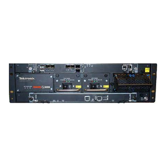
Rev. 002-140228 G10 Probe Overview G10 Rear View Figure 1.3 shows rear views of the GeoProbe G10. The IIC RTM installed in Slot 2 (top slot) varies depending on the G10 configuration. SRM200 RTM ESD Bond Point Applications Blade RTM... -
Page 15: Network Connectivity
IAP200/PRM200 RTM or IAP320/PRM300 RTM configurations. Primary Interface 2 (Port B) is optional and only used in redundant configurations. Figure 1.4 - Ethernet Connections G10 Hardware Maintenance Guide 7.13.2 Tektronix Communications | For Licensed Users | Unauthorized Duplication and Distribution Prohibited... -
Page 16: Default Port Settings
10G/1G/100M IAP320 1G/100M IAP200 1G/100M IAP100 ETH A, B 1G/100M SHMM MGMT 100M a. Not supported on Control Plane or Media probes. G10 Hardware Maintenance Guide 7.13.2 Tektronix Communications | For Licensed Users | Unauthorized Duplication and Distribution Prohibited... -
Page 17: Time Synchronization
G10 Probe Overview YNCHRONIZATION The GeoProbe G10 system time stamps all captured messages, generated alarms, and events to a common time base, allowing the Iris system to provide detailed, network-wide traces and event occurrence reporting. Inter-node timing and message paths can also be analyzed throughout the network. -
Page 18: G10 Media Probe Configuration
G10 Probe Overview G10 M EDIA ROBE ONFIGURATION To support RTP monitoring, Tektronix also provides a multiprobe configuration called the G10 Media Probe. The G10 Media probe consists of two G10 chassis with the supported configurations listed in Table 1.3. See Figure 1.5... -
Page 19: G10 Control Plane Probe Configuration
MGCP DIAMETER (S6a) H.323 GTPv2-C (S10, inter-MME) H.248 DIAMETER SgsAP SIGTRAN G10 Hardware Maintenance Guide 7.13.2 Tektronix Communications | For Licensed Users | Unauthorized Duplication and Distribution Prohibited... - Page 20 G10 Control Plane Installation Guide. Figure 1.7 shows the front view of the G10 Control Plane probe components. Figure 1.7 - G10 Control Plane Probe (Front) G10 Hardware Maintenance Guide 7.13.2 Tektronix Communications | For Licensed Users | Unauthorized Duplication and Distribution Prohibited...
- Page 21 G10 Probe Overview Figure 1.8 shows the rear view of the G10 Control Plane probe components. Figure 1.8 - G10 Control Plane Probe (Rear) G10 Hardware Maintenance Guide 7.13.2 Tektronix Communications | For Licensed Users | Unauthorized Duplication and Distribution Prohibited...
-
Page 22: Chapter 2 Chassis Subsystem
GeoProbe G10 service-related hardware and software. The Chassis subsystem of the GeoProbe G10 enables scalable reliability through the use of either independent or redundant functions throughout the chassis. Most electronic modules, blades and cards are Field Replaceable Units (FRUs). -
Page 23: Shelf Manager
RJ45 jacks each capable of connecting to 10/100 Mbps networks. The modules provide redundant shelf management functionality utilizing an active/ standby architecture and is based on a proven shelf management design. G10 Hardware Maintenance Guide 7.13.2 Tektronix Communications | For Licensed Users | Unauthorized Duplication and Distribution Prohibited... -
Page 24: Rear Panel Leds
BLINKING—Link and activity. OFF—Otherwise. Ethernet GREEN Indicates system manager Ethernet link availability. Management Link GREEN—The link is available. OFF—Otherwise. G10 Hardware Maintenance Guide 7.13.2 Tektronix Communications | For Licensed Users | Unauthorized Duplication and Distribution Prohibited... -
Page 25: Rear Panel Connectors
Operations, Administration, and Maintenance (OAM). Ethernet Uplink In some configurations, this is used to connect to the Connector management port on the disk enclosure. G10 Hardware Maintenance Guide 7.13.2 Tektronix Communications | For Licensed Users | Unauthorized Duplication and Distribution Prohibited... -
Page 26: Power Entry Modules (Pems)
Power and Ground Requirements. Refer to Maintenance Guidelines for replacement details. G10 Front View G10 Rear View Figure 2.3 - DC PEMs G10 Hardware Maintenance Guide 7.13.2 Tektronix Communications | For Licensed Users | Unauthorized Duplication and Distribution Prohibited... -
Page 27: Front Panel Leds
Please ensure proper cabling if your equipment and cabling use nonstandard DC electrical color coding. Improper cabling can cause damage to equipment or personal injury. Contact Tektronix to request specially labeled power cables (-48V = Red, Return = Black) for the G10 chassis and the storage enclosures. -
Page 28: Ac Pems
Figure 2.5 - G10 AC PEMs Front Panel LEDs Figure 2.6 displays the AC Front Panel PEM LED. Figure 2.6 - AC PEM Front Panel LED G10 Hardware Maintenance Guide 7.13.2 Tektronix Communications | For Licensed Users | Unauthorized Duplication and Distribution Prohibited... -
Page 29: Fan Trays
Refer to Replacing the Fan Tray Replacing G10 Chassis Air Filters for replacement details. Front Fan Tray Figure 2.7 - Front Fan Tray G10 Hardware Maintenance Guide 7.13.2 Tektronix Communications | For Licensed Users | Unauthorized Duplication and Distribution Prohibited... -
Page 30: Electro-Static Discharge Points
Front ESD Figure 2.8 - Front ESD Point Figure 2.9 displays the rear ESD point. Rear ESD Figure 2.9 - Rear ESD Point G10 Hardware Maintenance Guide 7.13.2 Tektronix Communications | For Licensed Users | Unauthorized Duplication and Distribution Prohibited... -
Page 31: Chapter 3 Blades And Rtms
Blades and RTMs VERVIEW The GeoProbe G10 is a modular device consisting of blades, Rear Transition Modules (RTMs), and other hardware components that allow minimal risk and dependency on other hardware devices. The probe is scalable and includes user-plane monitoring with high IP traffic networks. -
Page 32: Iris Interface Card
A total of four LEDs are visible from the left side of the IIC100 or IIC200 front panel that are part of the CAB100 carrier blade (see Figure 3.2). Figure 3.2 - IIC100 or IIC200 Front Panel LEDs G10 Hardware Maintenance Guide 7.13.2 Tektronix Communications | For Licensed Users | Unauthorized Duplication and Distribution Prohibited... - Page 33 OFF—No errors. RTM SAS GREEN Green LED indicates status of the SAS RTM. SOLID GREEN—No errors. OFF—Fault condition. G10 Hardware Maintenance Guide 7.13.2 Tektronix Communications | For Licensed Users | Unauthorized Duplication and Distribution Prohibited...
-
Page 34: Iic200
The four LEDs visible from the left side of the IIC200 front panel are part of the CAB100 carrier blade (Figure 3.3). Refer to the IIC LEDs section for details. G10 Hardware Maintenance Guide 7.13.2 Tektronix Communications | For Licensed Users | Unauthorized Duplication and Distribution Prohibited... -
Page 35: Fpc200 Amc
AMCs. FPC200 AMC LEDs Figure 3.5 shows the FPC200 AMC LEDs located on the front panel. Figure 3.5 - FPC200 AMC LEDs G10 Hardware Maintenance Guide 7.13.2 Tektronix Communications | For Licensed Users | Unauthorized Duplication and Distribution Prohibited... - Page 36 Note: When this board needs to be removed, you will be removing the entire IIC200. Refer to Iris Interface Card (IIC100 or IIC200) more information. G10 Hardware Maintenance Guide 7.13.2 Tektronix Communications | For Licensed Users | Unauthorized Duplication and Distribution Prohibited...
-
Page 37: Lpc200 Amc
1 GbE Port 1 and 2 1/10 GbE Port 7 and 8 1/10 GbE Port 5 and 6 Figure 3.7 - LPC200 AMC Connectors G10 Hardware Maintenance Guide 7.13.2 Tektronix Communications | For Licensed Users | Unauthorized Duplication and Distribution Prohibited... - Page 38 GREEN Indicates the health of the device. GREEN = No errors. OFF = Out of service. G10 Hardware Maintenance Guide 7.13.2 Tektronix Communications | For Licensed Users | Unauthorized Duplication and Distribution Prohibited...
-
Page 39: Iic200 Rtms
Provides two Gigabit Ethernet links for connectivity to controller enclosure Sends and receives data to the disk array storage subsystem G10 Hardware Maintenance Guide 7.13.2 Tektronix Communications | For Licensed Users | Unauthorized Duplication and Distribution Prohibited... - Page 40 10G Ethernet SFP connections used in multi-cage configurations for intercage communications. SAS 1–2 Provides connectivity to the external disk array storage system. G10 Hardware Maintenance Guide 7.13.2 Tektronix Communications | For Licensed Users | Unauthorized Duplication and Distribution Prohibited...
- Page 41 Indicates 10 Gigabit Ethernet link status. GREEN = Ethernet link is trained at 10 Gb/s speed. OFF = no Ethernet link established G10 Hardware Maintenance Guide 7.13.2 Tektronix Communications | For Licensed Users | Unauthorized Duplication and Distribution Prohibited...
-
Page 42: Iic100
ATCA carrier card (CAB100) FPC100 AMC LPC100 AMC Iris Interface Card (IIC100) LEDs LPC100 AMC FPC100 AMC Figure 3.12 - G10 IIC100 G10 Hardware Maintenance Guide 7.13.2 Tektronix Communications | For Licensed Users | Unauthorized Duplication and Distribution Prohibited... -
Page 43: Fpc100 Amc
FPC100 AMC LEDs Figure 3.14 shows the FPC100 AMC LEDs located on the front panel. Figure 3.14 - FPC100 AMC Front Panel LEDs G10 Hardware Maintenance Guide 7.13.2 Tektronix Communications | For Licensed Users | Unauthorized Duplication and Distribution Prohibited... - Page 44 Note: When this board needs to be removed, you will be removing the entire Iris Interface Controller blade. Refer to Iris Interface Card (IIC100 or IIC200) for more information. G10 Hardware Maintenance Guide 7.13.2 Tektronix Communications | For Licensed Users | Unauthorized Duplication and Distribution Prohibited...
-
Page 45: Lpc100 Amc
LPC100 AMC LEDs. Health Hot Swap GbE Port GbE Port Activity LED Link LED Figure 3.16 - LPC100 AMC LEDs G10 Hardware Maintenance Guide 7.13.2 Tektronix Communications | For Licensed Users | Unauthorized Duplication and Distribution Prohibited... -
Page 46: Iic100 Rtms
Provides two Gigabit Ethernet links for connectivity to second controller enclosure Sends and receives data to the disk array storage subsystem G10 Hardware Maintenance Guide 7.13.2 Tektronix Communications | For Licensed Users | Unauthorized Duplication and Distribution Prohibited... - Page 47 These connectors are not used. XLink 1–4 These connectors are not used. SAS 1–2 This connector provides connectivity to the external disk array storage system. G10 Hardware Maintenance Guide 7.13.2 Tektronix Communications | For Licensed Users | Unauthorized Duplication and Distribution Prohibited...
- Page 48 Indicates SAS link connectivity status. GREEN—No errors; SAS link is established. RED—An error occurred. OFF—No SAS link is established. G10 Hardware Maintenance Guide 7.13.2 Tektronix Communications | For Licensed Users | Unauthorized Duplication and Distribution Prohibited...
- Page 49 Mixed 1G and 10G Ethernet probe installations with IIC200 supporting eHRPD monitoring The TRM100 RTM connects to the back of the GeoProbe G10 chassis in the upper slot location and performs the following functions: Communicates the board’s health and configuration status to its counterpart IPMC on ...
- Page 50 RJ45 pin assignments for the SYSCLK connectors. Table 3.12 - SYSCLK RJ45 Pin Assignments Description CARR_CLK1A+ CARR_CLK1A- CARR_CLK2A+ no connect no connect CARR_CLK2A- CARR_CLK3A+ CARR_CLK3A- G10 Hardware Maintenance Guide 7.13.2 Tektronix Communications | For Licensed Users | Unauthorized Duplication and Distribution Prohibited...
- Page 51 SYSCLK is TERMINATED with a 200 Ω pull-down Down (closed/on) TERMINATED resistor. ALL TRM100 RTM SYSCLK switches on the Media Probe Primary and Expansion chassis must use this setting. G10 Hardware Maintenance Guide 7.13.2 Tektronix Communications | For Licensed Users | Unauthorized Duplication and Distribution Prohibited...
- Page 52 These indicate the status of the traffic running over the connection. BLINKING YELLOW—10-Gb Ethernet activity occurring. OFF—no 10-Gb Ethernet activity. G10 Hardware Maintenance Guide 7.13.2 Tektronix Communications | For Licensed Users | Unauthorized Duplication and Distribution Prohibited...
-
Page 53: Applications Blade
Provides the Ethernet connection to customer LAN Enables S2D functionality (LT and ST) Iris currently supports the following applications blades: IAP320/IAP200 IAP100 G10 Hardware Maintenance Guide 7.13.2 Tektronix Communications | For Licensed Users | Unauthorized Duplication and Distribution Prohibited... -
Page 54: Iap320/Iap200
Supports PRM200 RTM Figure 3.24 shows an example of the applications blade. IAP320 IAP200 Figure 3.24 - G10 IAP320 and IAP200 G10 Hardware Maintenance Guide 7.13.2 Tektronix Communications | For Licensed Users | Unauthorized Duplication and Distribution Prohibited... -
Page 55: Iap320
F1-F2 (L) GREEN Fabric Interface Link Indicator GREEN = The Ethernet link is up. OFF = No link established. G10 Hardware Maintenance Guide 7.13.2 Tektronix Communications | For Licensed Users | Unauthorized Duplication and Distribution Prohibited... - Page 56 OFF—The blade is operational, and it is unsafe to extract BLINKING BLUE—The module is in a transition between standby mode and operational mode. G10 Hardware Maintenance Guide 7.13.2 Tektronix Communications | For Licensed Users | Unauthorized Duplication and Distribution Prohibited...
- Page 57 For best display results, the terminal should be set to 80 columns by 25 lines. USB 1–2 These connectors are a standard USB 2.0 used for service and maintenance. G10 Hardware Maintenance Guide 7.13.2 Tektronix Communications | For Licensed Users | Unauthorized Duplication and Distribution Prohibited...
-
Page 58: Iap200
ETH Activity LED YELLOW Indicates the status of Ethernet traffic on the connection. YELLOW—Ethernet activity occurring. OFF—No Ethernet activity occurring. G10 Hardware Maintenance Guide 7.13.2 Tektronix Communications | For Licensed Users | Unauthorized Duplication and Distribution Prohibited... - Page 59 IAP200 Connectors Figure 3.26 displays the IAP200 connectors. USB Ports Serial Console Port Figure 3.28 - IAP200 Connectors G10 Hardware Maintenance Guide 7.13.2 Tektronix Communications | For Licensed Users | Unauthorized Duplication and Distribution Prohibited...
-
Page 60: Prm300 Rtm/Prm200 Rtm
The RTMs connect to the rear of the respective IAP. The RTM performs the following functions: Provides cable connections to the disk array Provides hard drive for operating system Includes an IPMC G10 Hardware Maintenance Guide 7.13.2 Tektronix Communications | For Licensed Users | Unauthorized Duplication and Distribution Prohibited... - Page 61 GREEN or RED Indicates the health of the PRM200 RTM. GREEN—No errors. RED—An error occurred. OFF—The board is not powered on. G10 Hardware Maintenance Guide 7.13.2 Tektronix Communications | For Licensed Users | Unauthorized Duplication and Distribution Prohibited...
- Page 62 Redundant Primary 1G Ethernet LAN (uplink to server). Only used for redundant Primary LAN configuration. Supports 10G/1G/100Mb; normal usage is 1G/100Mb for OAM. G10 Hardware Maintenance Guide 7.13.2 Tektronix Communications | For Licensed Users | Unauthorized Duplication and Distribution Prohibited...
-
Page 63: Iap100
PICMG 3.1 (option 9 or 1) compliant. The IAP100 supports the PRM100 RTM or the SSD-3400 RTM. SAS AMC IAP100 Figure 3.32 - G10 IAP100 G10 Hardware Maintenance Guide 7.13.2 Tektronix Communications | For Licensed Users | Unauthorized Duplication and Distribution Prohibited... -
Page 64: Iap100 Leds
OFF—The module is operational, and it is unsafe to extract it. BLINKING BLUE—The module is in a transition between standby mode and operational mode. G10 Hardware Maintenance Guide 7.13.2 Tektronix Communications | For Licensed Users | Unauthorized Duplication and Distribution Prohibited... -
Page 65: Iap100 Connectors
For best display results, the terminal should be set to 80 columns by 25 lines. USB 1–2 Standard USB 2.0 used for service and maintenance. SAS Connectors Part of the AMC. G10 Hardware Maintenance Guide 7.13.2 Tektronix Communications | For Licensed Users | Unauthorized Duplication and Distribution Prohibited... -
Page 66: Sas Amc
SAS AMC Connectors The SAS AMC contains SAS Port 1 and SAS Port 2 that provide connectivity to the storage enclosures. G10 Hardware Maintenance Guide 7.13.2 Tektronix Communications | For Licensed Users | Unauthorized Duplication and Distribution Prohibited... -
Page 67: Iap100 Rtms
Provides hard drive for operating system Includes an IPMC Figure 3.36 displays the PRM100 RTM. Figure 3.36 - PRM100 RTM G10 Hardware Maintenance Guide 7.13.2 Tektronix Communications | For Licensed Users | Unauthorized Duplication and Distribution Prohibited... - Page 68 The PRM100 indicators provide status and error information. The LED indicators are located on the face plate of the board (see Figure 3.37). Figure 3.37 - PRM100 LEDs G10 Hardware Maintenance Guide 7.13.2 Tektronix Communications | For Licensed Users | Unauthorized Duplication and Distribution Prohibited...
- Page 69 SFP Sockets (two) Not used. RS-232 Serial Port Not used. SAS Ports (two) Provides connectivity to storage subsystem. USB Port Not used. G10 Hardware Maintenance Guide 7.13.2 Tektronix Communications | For Licensed Users | Unauthorized Duplication and Distribution Prohibited...
-
Page 70: Interconnect Card
Deep Packet Classification (DPC). Refer to 10G Interconnect Card for installation and removal procedures. 10G Interconnect Cards Figure 3.39 - G10 Chassis Rear - 10G Interconnect Cards G10 Hardware Maintenance Guide 7.13.2 Tektronix Communications | For Licensed Users | Unauthorized Duplication and Distribution Prohibited... -
Page 71: 10G Interconnect Card Leds
OFF—An error has occurred, and the card is not operating properly. OOS (failure) Indicates card status. RED—The card is out of service. OFF—The card is working properly. G10 Hardware Maintenance Guide 7.13.2 Tektronix Communications | For Licensed Users | Unauthorized Duplication and Distribution Prohibited... -
Page 72: 10G Interconnect Card Connectors
FPC100 AMC IIC200 AMCs LPC200 AMC FPC200 AMC IAP100 AMC SAS AMC Rear Transition Modules (RTMs) IIC100 RTMs SRM100 RTM TRM100 RTM G10 Hardware Maintenance Guide 7.13.2 Tektronix Communications | For Licensed Users | Unauthorized Duplication and Distribution Prohibited... - Page 73 SSD-3400 RTM IAP200 RTM PRM200 RTM IAP320 RTM PRM300 RTM Storage Enclosures RAID Storage Enclosure SA100R SA200R JBOD Storage Enclosure SA100J SA200J G10 Hardware Maintenance Guide 7.13.2 Tektronix Communications | For Licensed Users | Unauthorized Duplication and Distribution Prohibited...
-
Page 74: Chapter 4 Storage Subsystem
Redundant, hot swappable fans and AC and DC power units Dual, hot-swappable IO modules or controller modules Hot-swappable disk drives G10 Hardware Maintenance Guide 7.13.2 Tektronix Communications | For Licensed Users | Unauthorized Duplication and Distribution Prohibited... -
Page 75: Supported Models
Requires 2 rack units (2U) of space SAS connectors SA200R/ SA200J/SA210J support 6 Gbps connectors SA100R/SA100J support 3 Gbps connectors G10 Hardware Maintenance Guide 7.13.2 Tektronix Communications | For Licensed Users | Unauthorized Duplication and Distribution Prohibited... - Page 76 Controller enclosures support configurable raw packet capture rates: Two SA100R controllers - up to 6 Gbps One SA200R controller - up to 10 Gbps G10 Hardware Maintenance Guide 7.13.2 Tektronix Communications | For Licensed Users | Unauthorized Duplication and Distribution Prohibited...
-
Page 77: Disk Enclosure Front Panels
0 to 11 from left to right as shown in the graphic. Figure 4.3 - Near-Line SAS Disk Enclosure Front Panel (SA210J) G10 Hardware Maintenance Guide 7.13.2 Tektronix Communications | For Licensed Users | Unauthorized Duplication and Distribution Prohibited... -
Page 78: Front Panel Leds
OFF—both power supplies are off; the system is powered off. Temperature Fault Valid options are: GREEN ON—the enclosure temperature is normal. YELLOW ON—the enclosure temperature is above threshold. G10 Hardware Maintenance Guide 7.13.2 Tektronix Communications | For Licensed Users | Unauthorized Duplication and Distribution Prohibited... -
Page 79: Disk Enclosure Rear Panel
Please ensure proper cabling if your equipment and cabling use nonstandard DC electrical color coding. Improper cabling can cause damage to equipment or personal injury. Contact Tektronix to request specially labeled power cables (-48V = Red, Return = Black) for the G10 chassis and the storage enclosures. - Page 80 This LED displays the color GREEN. Valid options are: ON—The port is connected, and the link is up. OFF—The port is empty, or the link is down. G10 Hardware Maintenance Guide 7.13.2 Tektronix Communications | For Licensed Users | Unauthorized Duplication and Distribution Prohibited...
-
Page 81: Sa200R Controller Enclosure Connectors
The controller enclosure rear panel houses the SAS and Ethernet port connectors, power supplies, and power switches (see Figure 4.5). Figure 4.5 - SA100R Controller Enclosure Rear Panel (DC Power Supplies Shown) G10 Hardware Maintenance Guide 7.13.2 Tektronix Communications | For Licensed Users | Unauthorized Duplication and Distribution Prohibited... - Page 82 This LED displays the color GREEN. Valid options are: ON—The Ethernet link is up. OFF—The Ethernet port is not connected, or the link is down. G10 Hardware Maintenance Guide 7.13.2 Tektronix Communications | For Licensed Users | Unauthorized Duplication and Distribution Prohibited...
-
Page 83: Sa100R Controller Enclosure Connectors
Connects to G10. Ethernet Port Connects to G10. Service Ports Used only by service personnel. SAS Expansion Ports Connects to another expansion enclosure. G10 Hardware Maintenance Guide 7.13.2 Tektronix Communications | For Licensed Users | Unauthorized Duplication and Distribution Prohibited... -
Page 84: Sa100J, Sa200J, And Sa210J Expansion Enclosure Rear Panel
OFF—The DC output voltage is normal. Unit Locator This LED displays the color WHITE. Valid options are: OFF—Normal operation. BLINKING—Physically identifies the controller module. G10 Hardware Maintenance Guide 7.13.2 Tektronix Communications | For Licensed Users | Unauthorized Duplication and Distribution Prohibited... -
Page 85: Expansion Enclosure Connectors
Service Port Used only by service personnel. SAS Out Port Connects to another drive enclosure. SAS In Port Connects to another drive enclosure. G10 Hardware Maintenance Guide 7.13.2 Tektronix Communications | For Licensed Users | Unauthorized Duplication and Distribution Prohibited... -
Page 86: Chapter 5 Maintenance Guidelines
User Documentation Maintenance Guidelines VERVIEW This chapter provides the following sections: G10 Maintenance Procedures Storage Array Maintenance Procedures G10 Hardware Maintenance Guide 7.13.2 Tektronix Communications | For Licensed Users | Unauthorized Duplication and Distribution Prohibited... -
Page 87: G10 Maintenance Procedures
IIC100 8x 1GB Blade set includes the following: AMC Carrier Blade CAB100 LPC100 AMC FPC100 AMC SRM100 RTM G10 Hardware Maintenance Guide 7.13.2 Tektronix Communications | For Licensed Users | Unauthorized Duplication and Distribution Prohibited... - Page 88 Storage Enclosures Storage Enclosure Air Filters Storage Enclosure Power Supplies SAS RAID Storage Enclosure SA100R or SA200R SAS Expansion Enclosure SA100J, SA200J, SA210J G10 Hardware Maintenance Guide 7.13.2 Tektronix Communications | For Licensed Users | Unauthorized Duplication and Distribution Prohibited...
-
Page 89: Removing And Replacing A Pem
If power is connected to the shelf, ensure that the breaker is in the OFF position before you insert or extract a PEM. G10 Hardware Maintenance Guide 7.13.2 Tektronix Communications | For Licensed Users | Unauthorized Duplication and Distribution Prohibited... - Page 90 Please ensure proper cabling if your equipment and cabling uses nonstandard DC electrical color coding. Improper cabling can cause damage to equipment or personal injury. Contact Tektronix to request specially labeled power cables (-48V = Red, Return = Black) for the G10 chassis and the storage enclosures.
-
Page 91: Replacing An Ac Pem
Electrostatic discharge can damage circuits or shorten their life. Before touching the blade or electronic components, ensure that you are working in an ESD-safe environment. G10 Hardware Maintenance Guide 7.13.2 Tektronix Communications | For Licensed Users | Unauthorized Duplication and Distribution Prohibited... - Page 92 Connect the AC power cord to the back of the AC PEM. Connect the AC power cord to the rack power supply. G10 Hardware Maintenance Guide 7.13.2 Tektronix Communications | For Licensed Users | Unauthorized Duplication and Distribution Prohibited...
- Page 93 Remove and insert the PEM again to be sure that it is properly seated and secure. If the LED lights again, contact Tektronix Communications Customer Support. LED GREEN The power is connected correctly. G10 Hardware Maintenance Guide 7.13.2 Tektronix Communications | For Licensed Users | Unauthorized Duplication and Distribution Prohibited...
-
Page 94: Replacing The Fan Tray
Running a fan on high speed for a long time can shorten the fan’s life and can exceed the allowable acoustic noise limits. Replace the fan tray as soon as possible. G10 Hardware Maintenance Guide 7.13.2 Tektronix Communications | For Licensed Users | Unauthorized Duplication and Distribution Prohibited... - Page 95 Grasp the handle and pull the tray carefully out of the shelf (see Figure 5.6). Figure 5.6 - Pulling Out the Fan Tray (Rear) G10 Hardware Maintenance Guide 7.13.2 Tektronix Communications | For Licensed Users | Unauthorized Duplication and Distribution Prohibited...
- Page 96 5.8). The fans start rotating during this step. Figure 5.8 - Rear Fan Tray Fasten the three mounting screws of the tray. G10 Hardware Maintenance Guide 7.13.2 Tektronix Communications | For Licensed Users | Unauthorized Duplication and Distribution Prohibited...
-
Page 97: Replacing G10 Chassis Air Filters
Otherwise, dust may fall and soil the new bottom filter when you remove the top filter. To ensure that the G10 probe operates efficiently, Tektronix requires the air filters to be changed every 3 months. - Page 98 Figure 5.9 - Top Air Filter Frame Removal Pull the frame carefully out of the chassis (Figure 5.10). Figure 5.10 - Top Air Filter Frame Removal G10 Hardware Maintenance Guide 7.13.2 Tektronix Communications | For Licensed Users | Unauthorized Duplication and Distribution Prohibited...
-
Page 99: Replacing The Bottom Air Filter
Electrostatic discharge can damage circuits or shorten their life. Before touching the blade or electronic components, ensure that you are working in an ESD-safe environment. Ensure that a new replacement filter is available. G10 Hardware Maintenance Guide 7.13.2 Tektronix Communications | For Licensed Users | Unauthorized Duplication and Distribution Prohibited... - Page 100 Detach the air filter from its frame. Attach the new filter to the frame. Ensure that it is aligned with the frame. G10 Hardware Maintenance Guide 7.13.2 Tektronix Communications | For Licensed Users | Unauthorized Duplication and Distribution Prohibited...
- Page 101 Push the frame downward until it snaps in place. Figure 5.14 - Bottom Air Filter Replacement Insert the front fan tray (refer to Replacing the Fan Tray). G10 Hardware Maintenance Guide 7.13.2 Tektronix Communications | For Licensed Users | Unauthorized Duplication and Distribution Prohibited...
-
Page 102: G10 Blade Removal/Replacement Procedures
Step Action Pinch the latch and lever on the right ejector handle and pull the handle outward slightly as shown (Figure 5.15). G10 Hardware Maintenance Guide 7.13.2 Tektronix Communications | For Licensed Users | Unauthorized Duplication and Distribution Prohibited... - Page 103 Gently remove the blade from the chassis. To reinstall the blade or install a new blade, refer to Installing the IAP100. G10 Hardware Maintenance Guide 7.13.2 Tektronix Communications | For Licensed Users | Unauthorized Duplication and Distribution Prohibited...
- Page 104 (Figure 5.17). Lever Latch Thumb Screw PWR LED Figure 5.17 - IAP100 Insertion G10 Hardware Maintenance Guide 7.13.2 Tektronix Communications | For Licensed Users | Unauthorized Duplication and Distribution Prohibited...
-
Page 105: Sas Amc (Iap100)
Push the AMC handle to the IN position. Perform the steps in the procedure Installing the IAP100 to reinsert the IAP100. G10 Hardware Maintenance Guide 7.13.2 Tektronix Communications | For Licensed Users | Unauthorized Duplication and Distribution Prohibited... -
Page 106: Iap200/Iap320
Hot Swap LED turns off. When the LED turns off, this indicates that the blade’s payload has been powered up and that the blade is active. G10 Hardware Maintenance Guide 7.13.2 Tektronix Communications | For Licensed Users | Unauthorized Duplication and Distribution Prohibited... - Page 107 While squeezing the handle’s lever and latch together, close the left and right ejector handles until the inner sides of the ejector handles are attached to the faceplate (Figure 5.21). G10 Hardware Maintenance Guide 7.13.2 Tektronix Communications | For Licensed Users | Unauthorized Duplication and Distribution Prohibited...
-
Page 108: Iris Interface Card (Iic100 Or Iic200)
If you are upgrading a probe by replacing the IIC100 with the IIC200, refer to the G10 Installation Guide for a detailed procedure. G10 Hardware Maintenance Guide 7.13.2 Tektronix Communications | For Licensed Users | Unauthorized Duplication and Distribution Prohibited... - Page 109 Hold Ejector Handle in Swing Handle Outward Start Position Forward Position Slightly Figure 5.23 - IIC Right Ejector Handle Hot Swap Positioning G10 Hardware Maintenance Guide 7.13.2 Tektronix Communications | For Licensed Users | Unauthorized Duplication and Distribution Prohibited...
- Page 110 (Figure 5.25). The IIC Hot Swap LED turns off. Figure 5.25 - G10 IIC Ejector Handle Closed G10 Hardware Maintenance Guide 7.13.2 Tektronix Communications | For Licensed Users | Unauthorized Duplication and Distribution Prohibited...
- Page 111 Position the left and right ejector handles as shown in Figure 5.26. Ejector Handle Figure 5.26 - G10 IIC Ejector Handle (Left) G10 Hardware Maintenance Guide 7.13.2 Tektronix Communications | For Licensed Users | Unauthorized Duplication and Distribution Prohibited...
- Page 112 Blade Latch Open Fully Release Ejector Handle Figure 5.28 - G10 IIC Ejector Handle - Open Blade Latch G10 Hardware Maintenance Guide 7.13.2 Tektronix Communications | For Licensed Users | Unauthorized Duplication and Distribution Prohibited...
- Page 113 Positioning Hole Positioning Ejector Handle Figure 5.30 - G10 IIC Positioning Pin Alignment G10 Hardware Maintenance Guide 7.13.2 Tektronix Communications | For Licensed Users | Unauthorized Duplication and Distribution Prohibited...
- Page 114 IIC100 + LED (Green) IIC100 FPC200 AMC CPU LED (Green) IIC200 + LED (Green) IIC200 Figure 5.32 - G10 IIC100 and IIC200 LED Verification G10 Hardware Maintenance Guide 7.13.2 Tektronix Communications | For Licensed Users | Unauthorized Duplication and Distribution Prohibited...
-
Page 115: Lpc And Fpc Amcs (Iic100 Or Iic200)
Push the AMC handle to the IN position. Reinsert the IIC. Refer to Installing the IIC100 or IIC200 for details. G10 Hardware Maintenance Guide 7.13.2 Tektronix Communications | For Licensed Users | Unauthorized Duplication and Distribution Prohibited... -
Page 116: Rtms
Pinch the latch and lever on the RTM right ejector handle and pull the handle outward slightly. The blue Hot Swap LED starts to blink. G10 Hardware Maintenance Guide 7.13.2 Tektronix Communications | For Licensed Users | Unauthorized Duplication and Distribution Prohibited... - Page 117 You can perform one of the following: Remove the RTM. Push the latch and lever back in until the Hot Swap LED turns off. G10 Hardware Maintenance Guide 7.13.2 Tektronix Communications | For Licensed Users | Unauthorized Duplication and Distribution Prohibited...
-
Page 118: 10G Interconnect Card
Slide the card into the shelf by using the extraction handles until you feel resistance. Wait until the blue LED is illuminated. G10 Hardware Maintenance Guide 7.13.2 Tektronix Communications | For Licensed Users | Unauthorized Duplication and Distribution Prohibited... - Page 119 Wait until the blue LED illuminates solid blue. Remove the card from the shelf using the extraction handles. Insert a replacement card; refer to Installing the 10G Interconnect Card. G10 Hardware Maintenance Guide 7.13.2 Tektronix Communications | For Licensed Users | Unauthorized Duplication and Distribution Prohibited...
-
Page 120: Replacing G10 Shelf Managers (Shmms)
Slide the board into the shelf by using the extraction handles until you feel resistance. Wait until the blue Hot Swap LED is illuminated. G10 Hardware Maintenance Guide 7.13.2 Tektronix Communications | For Licensed Users | Unauthorized Duplication and Distribution Prohibited... -
Page 121: Replacing The Second (Active) Shmm
Run the status on the both SHMMs to verify the “active” status. Tektronix Communications Customer Support will complete the probe setup to provision the IP addresses of the new SHMMs. G10 Hardware Maintenance Guide 7.13.2 Tektronix Communications | For Licensed Users | Unauthorized Duplication and Distribution Prohibited... -
Page 122: Serial Over Lan (Sol) Support
G10 Probe and Array Start Up/Shut Down Sequence Tektronix recommends powering the probes and associated arrays on and off in a specific sequence. The equipment can withstand unexpected power outages; but a proper power on/off sequence should be followed whenever possible. - Page 123 TRM100 RTM, indicating that there are no errors. Verify that the + LED on PRM200/PRM300 RTM is GREEN, indicating that there are no errors. G10 Hardware Maintenance Guide 7.13.2 Tektronix Communications | For Licensed Users | Unauthorized Duplication and Distribution Prohibited...
-
Page 124: Shut Down Procedure
RED (board booting) to AMBER (applications starting) to OFF, indicating that the probe is up. If LEDs are behaving differently than described in this procedure, contact Tektronix Communications Customer Support. For multiprobe configurations, after the G10 Primary Chassis is powered up successfully, turn on the power to the G10 Expansion Chassis. -
Page 125: Storage Array Maintenance Procedures
(one enclosure cannot have one SA100 controller and one SA200 controller). SA100 parts are not compatible with the SA200 enclosure. G10 Hardware Maintenance Guide 7.13.2 Tektronix Communications | For Licensed Users | Unauthorized Duplication and Distribution Prohibited... -
Page 126: Replacing A Power Supply
- Loosen the cable-locking screws attaching the connector to the PSU. - Disconnect the power cable from the PSU. AC: Unplug the AC cable from the power supply unit. G10 Hardware Maintenance Guide 7.13.2 Tektronix Communications | For Licensed Users | Unauthorized Duplication and Distribution Prohibited... - Page 127 Do not lift the module by its latch; doing so can break the latch. Lift and carry the module using its metal casing. G10 Hardware Maintenance Guide 7.13.2 Tektronix Communications | For Licensed Users | Unauthorized Duplication and Distribution Prohibited...
-
Page 128: Installing The Power Supply
For AC power cables: - Ensure that the AC Module power switches are in the OFF position (if applicable). G10 Hardware Maintenance Guide 7.13.2 Tektronix Communications | For Licensed Users | Unauthorized Duplication and Distribution Prohibited... -
Page 129: Bezel (Air Filter) Procedures
Align the bezel assembly with the front of the enclosure so the integrated ear covers slide onto the push-fit ball studs, while taking care to guide the LED indicators through ear-cover openings (Figure 5.39). G10 Hardware Maintenance Guide 7.13.2 Tektronix Communications | For Licensed Users | Unauthorized Duplication and Distribution Prohibited... -
Page 130: Removing The Air Filter
Electrostatic discharge can damage circuits or shorten their life. Before touching the blade or electronic components, ensure that you are working in an ESD-safe environment. G10 Hardware Maintenance Guide 7.13.2 Tektronix Communications | For Licensed Users | Unauthorized Duplication and Distribution Prohibited... - Page 131 Tug the top of the filter frame gently to revolve it away from its vertical position and then pull upward to release the filter from the bezel’s two mounting channels (Figure 5.42). G10 Hardware Maintenance Guide 7.13.2 Tektronix Communications | For Licensed Users | Unauthorized Duplication and Distribution Prohibited...
-
Page 132: Replacing The Air Filter
On the back side of the bezel, insert the air filter with the foam facing toward the bezel’s vents. Align the bottom corners of the air filter per the thrust lines as (Figure 5.43). G10 Hardware Maintenance Guide 7.13.2 Tektronix Communications | For Licensed Users | Unauthorized Duplication and Distribution Prohibited... - Page 133 (Figure 5.44). Figure 5.44 - Air Filter Replacement G10 Hardware Maintenance Guide 7.13.2 Tektronix Communications | For Licensed Users | Unauthorized Duplication and Distribution Prohibited...
-
Page 134: Replacing A Controller Or Expansion Module
IrisView Alarm Browser to help isolate failed components. Disconnect any cables from the failed enclosure module. G10 Hardware Maintenance Guide 7.13.2 Tektronix Communications | For Licensed Users | Unauthorized Duplication and Distribution Prohibited... - Page 135 Figure 5.47 - Extracting a Controller Module Pull the module straight out of the enclosure (Figure 5.48). Figure 5.48 - Removing a Controller Module G10 Hardware Maintenance Guide 7.13.2 Tektronix Communications | For Licensed Users | Unauthorized Duplication and Distribution Prohibited...
-
Page 136: Installing The Controller Module
Check that the FRU OK LED (back) is green, indicating that the controller has completed initializing, is online, and is operating normally. Contact Tektronix Communications Customer Support to complete the controller/expansion module installation. G10 Hardware Maintenance Guide 7.13.2 Tektronix Communications | For Licensed Users | Unauthorized Duplication and Distribution Prohibited... -
Page 137: Replacing A Drive Module
Squeeze the latch release flanges inward to disengage the drive module (Figure 5.50). Figure 5.50 - Disengaging an Air Management Sled (AMS) Wait 20 seconds for the internal disks to stop spinning. G10 Hardware Maintenance Guide 7.13.2 Tektronix Communications | For Licensed Users | Unauthorized Duplication and Distribution Prohibited... -
Page 138: Installing Drive Modules
3.5” Drives — with the LEDs oriented to the left, slide the drive module into the drive slot as far as it will go (see Figure 5.52). Figure 5.52 - Installing a Drive Module G10 Hardware Maintenance Guide 7.13.2 Tektronix Communications | For Licensed Users | Unauthorized Duplication and Distribution Prohibited... -
Page 139: Replacing The Disk Array Chassis
Be sure to review Storage Array Maintenance Guidelines before proceeding to ensure component compatibility. G10 Hardware Maintenance Guide 7.13.2 Tektronix Communications | For Licensed Users | Unauthorized Duplication and Distribution Prohibited... -
Page 140: Removing The Disk Array Chassis
Extract all of the disks (HDDs) from the original disk array and slot them, in the same order, into the new disk array. G10 Hardware Maintenance Guide 7.13.2 Tektronix Communications | For Licensed Users | Unauthorized Duplication and Distribution Prohibited... -
Page 141: Installing The Disk Array Chassis
Power up the new disk array. Press the power switch, on both power supply units, to the ON position. (Figure 5.55) G10 Hardware Maintenance Guide 7.13.2 Tektronix Communications | For Licensed Users | Unauthorized Duplication and Distribution Prohibited... - Page 142 See the Iris Installation and Upgrade Guide to configure the G10 Probe and complete the disk array replacement. Contact Tektronix Communications Customer Support for assistance. G10 Hardware Maintenance Guide 7.13.2 Tektronix Communications | For Licensed Users | Unauthorized Duplication and Distribution Prohibited...
-
Page 143: Chapter 6 System Operating Specifications
Refer to the following sections for details: Physical Specifications Power and Ground Requirements Regulatory Specifications Safety Guidelines G10 Equipment Warning Labels G10 Hardware Maintenance Guide 7.13.2 Tektronix Communications | For Licensed Users | Unauthorized Duplication and Distribution Prohibited... -
Page 144: Physical Specifications
Removing a component requires a clearance of at least 15 inches (37 cm) in front of and behind the enclosure. G10 Hardware Maintenance Guide 7.13.2 Tektronix Communications | For Licensed Users | Unauthorized Duplication and Distribution Prohibited... -
Page 145: Power And Ground Requirements
OWER AND ROUND EQUIREMENTS The following sections list the power and ground requirements for the GeoProbe G10 and storage enclosures. Both units will require individual connections to earth ground for safety. The GeoProbe G10 provides dual-post connection for this purpose. The disk enclosure power cable includes an earth ground connection. -
Page 146: Ac Power Requirements
Please ensure proper cabling if your equipment and cabling uses nonstandard DC electrical color coding. Improper cabling can cause damage to equipment or personal injury. Contact Tektronix to request specially labeled power cables (-48V = Red, Return = Black) for the G10 chassis and the storage enclosures. -
Page 147: Environmental Specifications
Sound Power Level (L ): <78 dB at 27°C EGULATORY PECIFICATIONS The GeoProbe G10 is fully compliant with the following Safety and Electromagnetic Compatibility (EMC) specifications. Safety Compliance Table 6.4 lists the safety standards for which the GeoProbe G10 is fully compliant. -
Page 148: Emc Standards
EN55022, Class A British Standards - Information Technology 2010 CISPR 22: 2008 Equipment - Radio Disturbance Characteristics - Limits and Method of Measurement G10 Hardware Maintenance Guide 7.13.2 Tektronix Communications | For Licensed Users | Unauthorized Duplication and Distribution Prohibited... -
Page 149: Ce Mark
EMC Requirements - Part -1: General Requirements CE Mark The CE Marking on the GeoProbe G10 indicates that it is in compliance with the European Union’s EMC Directive, 2004/108/EC, and Low Voltage Directive 2006/95/EC. NEBS The G10 probe is compliant with NEBS level 3 per Bellcore GR-63-CORE and GR-1089- CORE (DC units). -
Page 150: Safety Guidelines
GeoProbe G10 Power Disconnect Always ensure you disconnect power to the GeoProbe G10 prior to servicing the unit. To disconnect power to the GeoProbe G10 DC unit, set the breakers on the PEM face plates to the OFF position (Figure 6.1). -
Page 151: Circuit Protection
FP100 Fuse Panel The FP100 is a GMT dual circuit fuse panel that provides DC power connection, input fusing, and circuit protection for the GeoProbe G10 and SAS Storage Array (see Figure 6.2). The fuse panel is not applicable in AC power configurations. - Page 152 Alarm contact relays Temperature -5 C to 55 C Humidity 0 to 90%, non-condensing Rack mounting Standard 19 inch rack, 1U high G10 Hardware Maintenance Guide 7.13.2 Tektronix Communications | For Licensed Users | Unauthorized Duplication and Distribution Prohibited...
-
Page 153: G10 Equipment Warning Labels
The system contains gaskets at the shelf and module level. The shelf is also fitted with ESD snaps for use with conductive wrist straps. Please take care for proper ESD protection of the operator. G10 Hardware Maintenance Guide 7.13.2 Tektronix Communications | For Licensed Users | Unauthorized Duplication and Distribution Prohibited... -
Page 154: Appendix Asfp Reference
This appendix provides reference information for the small form-factor pluggable (SFP) transceivers for the 1G ports and the 10G ports on the G10 probe. G10 Hardware Maintenance Guide 7.13.2 Tektronix Communications | For Licensed Users | Unauthorized Duplication and Distribution Prohibited... -
Page 155: Gb Port Sfps
1000base-LX Fiber Distance Tek P/N Finisar P/N Handle Color / Shape 1310 nm 119736700 FTLF1318P3BTL-TK Blue / Round multi- or single-mode G10 Hardware Maintenance Guide 7.13.2 Tektronix Communications | For Licensed Users | Unauthorized Duplication and Distribution Prohibited... -
Page 156: 1000Base-Sx Fiber
FTLF8519P3BNL-TK Black / Round multi-mode 1000base-T Copper Distance Tek P/N Finisar P/N Handle color / Shape RJ-45/cat5e 119738700 FCLF-8521-3 Yellow / Round G10 Hardware Maintenance Guide 7.13.2 Tektronix Communications | For Licensed Users | Unauthorized Duplication and Distribution Prohibited... -
Page 157: Gb Port Sfps
PRM200 RTM or PRM300 RTM (10G Ethernet Ports C and D) TRM100 (Four 10G Ethernet ports when used with IIC100) Figure A.2 - 10 GB Ethernet Ports G10 Hardware Maintenance Guide 7.13.2 Tektronix Communications | For Licensed Users | Unauthorized Duplication and Distribution Prohibited... -
Page 158: 10Gbase-Sr Fiber
-16 dBm (0 dBm maximum) 1300/1310 nm multi-mode (LX) -18 dBm (0 dBm maximum) 1310 nm single-mode (LX) -20 dBm (0 dBm maximum) G10 Hardware Maintenance Guide 7.13.2 Tektronix Communications | For Licensed Users | Unauthorized Duplication and Distribution Prohibited... -
Page 159: Installing Sfps
If replacing SFPs, procedures vary depending on the type of SFP replacement you are performing and the blade in which you are replacing it. Table A.2 summarizes the required steps for each scenario. G10 Hardware Maintenance Guide 7.13.2 Tektronix Communications | For Licensed Users | Unauthorized Duplication and Distribution Prohibited... -
Page 160: Iic200
1/10 GbE 5 1/10 GbE 6 1/10 GbE 7 1/10 GbE 8 GbE 3 GbE 2 GbE 4 Figure A.3 - IIC200 SFPs G10 Hardware Maintenance Guide 7.13.2 Tektronix Communications | For Licensed Users | Unauthorized Duplication and Distribution Prohibited... -
Page 161: Iic100
Transmit (TX) and the right port is Receive (RX). SFP Closed Handle in UP position TX Port RX Port (LEFT) (RIGHT) Figure A.5 - TRM100 RTM Paired with IIC100 G10 Hardware Maintenance Guide 7.13.2 Tektronix Communications | For Licensed Users | Unauthorized Duplication and Distribution Prohibited... -
Page 162: Prm200 Rtm Or Prm300 Rtm
Insert 10G SFPs with closed handle in UP position (Figure A.7): Xlink 1-4 ports—used in multiprobe configurations Four Xlink Ports Figure A.7 - SRM200 RTM SFPs G10 Hardware Maintenance Guide 7.13.2 Tektronix Communications | For Licensed Users | Unauthorized Duplication and Distribution Prohibited...
Need help?
Do you have a question about the GeoProbe G10 and is the answer not in the manual?
Questions and answers