Advertisement
Quick Links
Advertisement

Related Manuals for BT Redcare Essential Extra


Summary of Contents for BT Redcare Essential Extra
- Page 1 Essential Extra Installation Guide...
-
Page 2: Table Of Contents
Contents Introduction Mounting And Wiring Programming Configuration Disposal Glossary Of Terms Support... -
Page 3: Introduction
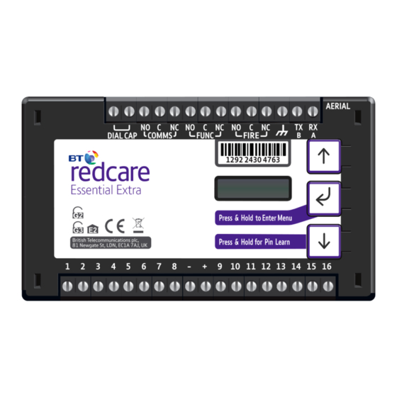
Introduction... - Page 4 The unit has 16 general purpose alarm inputs, and 3 outputs, making it suitable for connection to most common alarm panels. The unit is supplied already fitted with two BT Redcare enabled SIM cards, one an EE UK fixed SIM and a UK Roaming SIM. Both enabled for 4G/2G connectivity.
- Page 5 Specifications Size: 114mm x 67mm x 20mm Power: 9V – 30V Current: Average Average Max loading Normal Operation (inc relays and dial capture operated) 4G/4G unit @12V 110mA 190mA 4G/4G unit @24V 50mA 110mA Alarm inputs: 16 General purpose inputs 1-16. (-0.5V – 30V) Alarm threshold: High >2V, and Low <1.3V Outputs: 3 x Relay NO C NC (Comms, Func, Fire)
-
Page 6: Mounting And Wiring
Mounting and Wiring... - Page 7 Removal of Cover The top cover can be removed by gently releasing each of the 4 clips on the base of the unit by pushing the clips outward with a screwdriver blade. Regular access to the inside of the unit should not be required, although occasional access may be required to access the SIM cards.
- Page 8 Connection Terminals The screw terminals for the alarm inputs are suitable for use with a standard 3mm blade terminal screwdriver. Power connections Power to the unit is via 2 screw terminals at the centre, with positive to the right nearest Pin 9. The supply voltage range is 9V to 30V.
- Page 9 Carry out a survey to establish the best location. Mobile 1 Aerial Mobile 2 Aerial If necessary, a selection of high gain and extension aerials can be purchased from the BT Redcare shop at https://www.btinstallershop.com...
-
Page 10: Programming
Programming... - Page 11 Unit Initialisation The unit will immediately attempt to connect to the BT Redcare platform over the configured paths. The unit will typically complete path establishment in the following times from power up. Mobile 1 120s Mobile 2 180s Figure 4 – time to commission paths after unit power up Status display The unit clearly displays its status on the OLED.
- Page 12 Service Grade Redcare DP2 R Service Grade – shows the EN Performance category. The performance category can only be determined by the unit while in contact with the platform. The unit will not show the performance category until at least one path is registered and the profile can be retrieved from the platform. Alarms GPI Alarm Alarms Battery Low Battery...
- Page 13 Path: Mobile1 Mobile1 Strength Mobile1 Operator Registered 4G [ ] [-101] Path: Mobile2 Mobile2 Strength Mobile2 Operator Registered 4G [ ] [-103] Three Alarms GPI Alarm Service Grade Redcare DP2 R Figure 6 – typical display cycling on a fully commissioned unit with a good signal strength and pin 4 in the alarm or open state.
- Page 14 PIN inputs Of the 16 alarm pin inputs, all behave as general purposes inputs with the following exceptions. Pin 1 must be used for Fire alarm when ACK NAK outputs are used for Fire panels. The signalling unit, when configured, provides an acknowledge and not acknowledged indication via use of outputs 2 (Func) and 3 (Fire).
- Page 15 Output 2 (Func) Output 2 has a number of configuration options 1. Dual path fault: Will operate when both paths are in fault. 2. User control output: This can be switched on and off from the web portal or the app. 3.
- Page 16 Output 3 is set to User operated Fire output settings: To ensure that the Essential Extra units can inform the fire alarm panel of status as per the requirements of EN 54, the outputs need to be configured as follows.
-
Page 17: Configuration
Configuration... - Page 18 Pin Learn For speed of installation a single button press pin learn is available. All pins to be used should be wired in and all the pins should be in the non alarm state. No tampers should be active (if wired in) and Pin 4 (open /close) should represent the system being set/closed.
- Page 19 When in the main menu, each press of will step to the next menu item down. to step back up and eventually return to the top of the menu. The full main menu options are shown in Fig. 7. Pressing the Enter button on any menu item will enter the sub-menu and take you into edit mode. This will allow the function to be changed.
- Page 20 Inputs Pin Learn The polarity of pins can be learnt by pressing and holding the down arrow for 5s. The display will show notice done. Pin learn can also be carried out through the configuration menu. Example – to learn the pin polarity in the configuration menu:- Inputs Configuration Notice –...
- Page 21 Input Sense The polarity of the pins can manually be configured by the installer. This is additional to the pin learn function described earlier. Example – to configure pin 4 to be positive removed:- Inputs Configuration Pin Learn Inputs Sense Press until Input Sense 1 Input Sense 4...
- Page 22 Inputs EOL The alarm inputs (PINS) can be set to the following modes: - None - (Alarm & Restore) - EOL (Single end of line mode) - (Alarm, Restore & Cut) - DEOL (Dual End of line mode) - (Alarm, Restore, Cut & Short) Example –...
- Page 23 Outputs The three relay outputs can be configured as follows: 1. Output type 1 (Comms): - BSIA 175 Mode -operates when either path is in fault but in conjunction with Pin 11 ATS allows the panel to interrogate the device to determine a single or dual path fault (default). - Single path fault –...
- Page 24 Example – configure Output 1 (Comms) for a single path fault Inputs Configuration Output Type 1 Output Type BSIA 175 Output Type 1 * Output Type 1 * BSIA 175 Single Path Fault Press and hold Notice Saved! Access the configuration menu by holding Enter button for 3 seconds, press the Enter button again, the display will show pin learn.
- Page 25 Web Passcode This code is used to set up both the installer and customer app. The pass code will need to be entered by you and can be any 8 digits Inputs Configuration Web Passcode Network Press until shows Web Passcode * Web Passcode * 8765432 Use enter, up and down to change...
- Page 26 Serial Connection Panel type This menu selects the panel connection type for serial connected panels (RS232 or RS485). The panel list may change as we look to add more panels. Settings: • None • Menvier • Dimension GD 232 (Galaxy Dimension 48/96/264/520 (RS232 9600 8n1)) •...
- Page 27 Edit mode for that part of the menu can be exited at any time, without saving changes, by pressing for 5s. This will return you to the sub menu that you were making changes in. The configuration menu can be exited at any time without saving any changes by pressing for 5 seconds.
- Page 28 Restore Defaults The Restore defaults option on the menu can be used to set the unit back to factory default. That is all settings will be reset to their standard values. Example - setting the unit back to factory default. Inputs Configuration Notice –...
- Page 29 Remote control Log in with the BT username = xxxxx, password = xxxxxxxx This is available from the BT Redcare Technical Helpdesk or your Redcare account manager. Main Status Display When you first login you are presented with the main status page, you can return to this page at any time by clicking Main on the menu bar.
- Page 31 Status These icons show the status of the signalling paths and if there are any outstanding alarms. Green for the signalling path icons indicates signalling paths are successfully connected to the platform. Red indicates that a path is down. The bell icon is green in the example above as we have no alarms showing in the system messages box, which you would expect to see as the system will be set.
- Page 32 Pins shows the Name (if changed) and status of each of the PIN alarms. OK with green dot shows the pin is not in alarm and Alarm with the red dot if in alarm. It will also show if a PIN is in a cut or short state, with a blue dot and cut or short.
- Page 33 The below shows the most recent events. If you click on the drop down you are able to filter the events by type. Eg Alarms, System, Configuration or Connection.
- Page 34 This menu allows you to set up additional installer and end customer app access to the unit and change log in pin numbers. The settings menu has sub menus to be able to program the unit. The first screen gives you details of the device including MAC address and firmware version.
- Page 35 Status The status sub menu shows the status of the mobile paths. If they are online and connected, if its using 2G or 4G, the signal strength, which SIM and operator. 23410 - O2, 23415 - Vodafone, 23420 - Three, 23430 - EE There is also a Test Alarm function.
- Page 36 Network Under Network you are able to set up the Web Access Passcode. This should be entered if setting up App access. Enter an 8 digit number and save changes Make your changes and then click the save button. Program success will be displayed.
- Page 37 GPIO In this menu, by using the drop down arrows on each section, you can change any of the PIN input status from High (postive removed) to Low (positive removed). You can set up either end of line (EOL) or dual end of line (DEOL) for each PIN as required.
- Page 38 In the example below, we show PIN 8 as Active High, with DEOL monitoring. Output 2 is set to operate as a Fire NAK output (operates if an acknowledgement on a PIN 1 alarm is not received within 80 seconds). Make all the changes to the PIN inputs and outputs then click the save button to store your changes in the unit.
- Page 39 Name Editor It is possible to add names to the PIN inputs. This will then show up on the customer app and notifications. You can choose a description for the USER relay outputs. Click save when you have entered all the information.
- Page 40 Allows selection of the Serial connection for specific panel types. Select the drop down next to Type and you will get a list of panel types. Select the required panel type and connection type and then click save. Program success will be displayed. Ongoing development will add new panels over time.
- Page 41 Reports This allows you to set up a number of email addresses that could receive emails on the various options. e.g. Alarms and System mesages.
- Page 42 Defaults The above restores the unit to factory settings by clicking Reset to Defaults. Logout Clicking Logout will take you back to the sign in screen.
- Page 43 To 12V or 24V supply input resistor 2 Normally open contacts To Pin input Fig 8 You will need 1 x 3K3 and 1 x 10K resistors for each PIN with interconnection monitoring. www.btinstallershop.com Resistors are available from the BT Redcare installer shop.
- Page 44 3.3KΩ 1% 10KΩ 1% Fig 9 orange, orange, black, brown, brown brown, black, black, red, brown Resistor Item Code Label Colour Code 089446 Red Dot in packet 089447 Blue Dot in packet What happens when pins are configured and wired in this way The dual resistor EOL mode is able to detect four states: - Alarm event - restore...
- Page 45 Example configuration and wiring for connection to fire panel with interconnection monitoring Ensure that the required pins have Dual EOL enabled in the config menu in the example Pin 1 and Pin 8 have been enabled for this. Note it is available on pins 1 – 16 - Output 1 = Single path fail - Output 2 = Fire Nak - Output 3 = Fire Ack...
- Page 46 Should network connectivity be lost the SIM for Mobile 2 will try different networks, 4G and 2G. Should the unit lose connectivity with the BT Redcare platforms, or lose registration with the current base station, then the unit will roam onto the next available 4G or 2G network.
- Page 47 Example below shows connection via RS 485 to a Galaxy Dimension panel: Galaxy Dimension To other RS485 devices. Keypads RIO’s etc Figure 11 (not to scale) Connection Advice The unit should be connected to the Honeywell Galaxy panel as shown in figure 11, RS485A to A1 and RS485B to B1. Do not use the secondary data line (if your panel has one- A2/ B2) as it will not work.
- Page 48 Alarm List Description (zone) Inputs 1-16 1-16 323 (901-16) Low Battery 302 (999) Unit reboot 305 (995) Panel dial fail 314 (999) Software changed 304 (999) Panel message error 311 (997) Panel Connection (RS485) 356 (997) BSIA 175 Test 354 (998/999) Inputs 1-16 cut alarm 325 (901-16) Inputs 1-16 Short Alarm...
-
Page 49: Disposal
The manufacturer is not liable for any purely economic loss arising from any use of this equipment. All responsibility and liability in the use of BT Redcare products are assumed by the user. -
Page 50: Glossary Of Terms
Glossary of terms Alarm Receiving Centre BSIA British Security Industry Association Carrier Signal Quality (RSSI,BER) F175 Form 175 as issued by BSIA Greenwich Mean Time MMCX Micro Miniature Coaxial Connector OLED Organic Light Emitting Diode RSSI Received Signal strength indicator Return Path Signalling (An output that confirms delivery of PIN 4 to the ARC) Receive Serial Identity number - 12 digit unique identity number of a unit... -
Page 51: Support
Support For assistance with your BT Redcare installation, please contact the BT Redcare Helpdesk on: 0800 800 628 EN50136, EN50131, PD6669, PD6662 EN 54-21:2006 Alarm transmission and fault warning routing equipment for fire alarm systems Offices worldwide The services described in this publication are subject to availability and may be modified from time to time.
Need help?
Do you have a question about the Essential Extra and is the answer not in the manual?
Questions and answers