
Related Manuals for BT Redcare Essential Extra


Summary of Contents for BT Redcare Essential Extra
- Page 1 Essential Extra Installation Guide EN 50136-2: 2013 EN 50131-10: 2014 Cert No. 1270g...
-
Page 2: Table Of Contents
Panel Serial data connections Reports Dial capture Default Aerial connection Logout Programming Web portal and BT Redcare app Compliance with the user access level Unit initialisation requirements of EN 50136 Status display Signal strength Interconnection monitoring Guide to signal strength... -
Page 3: Introduction
The unit has 16 general purpose alarm inputs, and 3 outputs, making it suitable for connection to most common alarm panels. The unit is supplied already fitted with two BT Redcare enabled SIM cards, one an EE UK fixed SIM and a UK Roaming SIM. Both enabled for 4G/2G connectivity. -
Page 4: Specifications
Specifications Size: 114mm x 67mm x 20mm Weight: 139g Power: 9V – 30V Average Max loading (inc relays Current: Average Normal Operation and dial capture operated) 4G/4G unit @12V 110mA 241mA 4G/4G unit @24V 50mA 110mA Alarm inputs: 16 General purpose inputs 1–16. (-0.5V – 30V) Alarm threshold: High >2V, and Low <1.3V Outputs:... -
Page 5: Safety Notes
Safety notes Warning: Read all safety warnings and instructions. Failure to heed warnings and follow instructions may result in electric shock, fire risk and/or personal injury. Work area safety • Keep work area clean, well lit and free of obstacles. •... -
Page 6: Mounting And Wiring
Mounting and wiring Removal of cover The top cover can be removed by gently releasing each of the 4 clips on the base of the unit by pushing the clips outward with a screwdriver blade. Regular access to the inside of the unit should not be required, although occasional access may be required to access the SIM cards. -
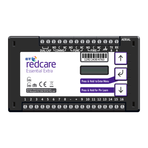
Page 7: Connection Terminals
1287 5675 8214 Connection terminals The screw terminals for the alarm inputs are suitable for use with a standard 3mm blade terminal screwdriver. Power connections Power to the unit is via 2 screw terminals at the centre, with positive to the right nearest Pin 9. The supply voltage range is 9V to 30V. -
Page 8: Outputs
The aerials should be placed in a vertical position and slightly apart to ensure a good wireless coverage. Carry out a survey to establish the best location. Mobile 1 Aerial Mobile 2 Aerial If necessary, a selection of high gain and extension aerials can be purchased from the BT Redcare shop at btinstallershop.com... -
Page 9: Programming
Programming Unit initialisation The unit will immediately attempt to connect to the BT Redcare platform over the configured paths. The unit will typically complete path establishment in the following times from power up. Mobile 1 120s Mobile 2 180s Figure 4 – time to commission paths after unit power up Status display The unit clearly displays its status on the OLED. -
Page 10: Signal Strength
Signal strength Signal strength that is: Signal strength that is: • On 2G below -90dBm = X will be displayed • On 4G below -120dBm = X will be displayed • On 4G between -120 and -110, 1 bar will •... -
Page 11: Pin Inputs
Pin inputs Of the 16 alarm pin inputs, all behave as general purposes inputs with the following exceptions. • Pin 1 must be used for Fire alarm when ACK NAK to Pin 13, the unit’s display will show the alarm outputs are used for Fire panels. - Page 12 Mobile 2 path fault output: In this case Output 1 is set as the Mobile 1 path To ensure that the Essential Extra units can inform the fault output, and Output 2 as the Mobile 2 path fire alarm panel of status as per the requirements of fault output.
-
Page 13: Configuration
Configuration Pin Learn For speed of installation a single button press Pin Learn is available. All pins to be used should be wired in and all the pins should be in the Press & Hold for Pin Learn non alarm state. No tampers should be active (if wired in) and Pin 4 (open/close) should represent the system being set/closed. -
Page 14: Button Configuration
Button configuration The button configuration mode is entered by holding down the centre configuration button (Enter) for 3s. The unit will then display ‘Configuration’. Configuration Press the Enter button again and the display will show the first menu option. Inputs Inputs When in the main menu, each press of will step to the next menu item down. -
Page 15: Main Menu Display
Main menu display Configuration Version Exit Serial Panel Restore Inputs Output Type Network Diagnostics Back Type Defaults Pin Learn Output Type 1 Output Type 2 Input Sense Panel Type Web Passcode Back Back Inputs EOL Output Type 3 Back Back Back Figure 7 –... - Page 16 Input Sense The polarity of the pins can manually be configured by the installer. This is in addition to the Pin Learn function described earlier. Example – to configure Pin 4 to be positive removed: Configuration Inputs ation Inputs Sense Pin Learn Press until Inputs Sense 4...
- Page 17 Inputs EOL The alarm inputs (pins) can be set to the following modes: • None – (Alarm and Restore) • EOL (Single end of line mode) – (Alarm, Restore and Cut) • DEOL (Dual end of line mode) – (Alarm, Restore, Cut and Short) Example –...
-
Page 18: Outputs
• RPS – return path signal operates in conjunction with Pin 4. • Fire NAK – Fire pin not acknowledged. Operates in conjunction with Pin 1. • Keyswitch – allows panel to be set/unset via the BT Redcare customer app. 3. Output type 3 (FIRE): •... - Page 19 Example – configure Output 1 (Comms) for a single path fault Configuration Inputs Output Type Output Type 1 BSIA 175 Output Type 1* Output Type 1* Single Path Fault BSIA 175 Press and hold Notice – Saved! • Access the configuration menu by holding Enter button for 3s. Press the Enter button again, the display will show ‘Pin Learn’.
-
Page 20: Network
Network Web passcode This code is used to set up both the installer and customer app. The pass code will need to be entered by you and can be any 8 digits. Configuration Inputs Network Web Passcode Press until shows Web Passcode* Web Passcode* 8765432... -
Page 21: Serial Connection Panel Type
Serial connection panel type This menu selects the panel connection type for serial connected panels (RS232 or RS485). Settings: • None • Menvier • Dimension GD 232 (Galaxy Dimension 48/96/264/520 (RS232 9600 8n1)) • Dimension GD 485 (Galaxy Dimension 48/96/264/520 (RS485)) •... -
Page 22: Diagnostics
Edit mode for that part of the menu can be exited at any time, without saving changes, by pressing for 5s. This will return you to the sub-menu that you were making changes in. The configuration menu can be exited at any time without saving any changes by pressing for 5s. -
Page 23: Remote Control
Remote control The descriptions below are when using web portal. The same menu options are available in the BT Redcare Installer app. Log in with the BT username = xxxxx, password = xxxxxxxx This is available from the BT Redcare Technical Helpdesk or your Redcare account manager. -
Page 24: Main Status Display
Main status display When you first log in you are Status System messages presented with the main status These icons show the status of The system messages box will page, you can return to this page the signalling paths and if there scroll though the key messages: at any time by clicking Main on are any outstanding alarms. -
Page 25: Pins
Pins Pins shows the Name (if changed) and status of each of the pin alarms. OK with green dot shows the pin is not in alarm and Alarm with the red dot if in alarm. It will also show if a pin is in a cut or short state, with a blue dot and cut or short. -
Page 26: Users
Users This menu allows you to set up additional installers and end customer app access to the unit and change login PIN numbers. To comply with EN 50136-2 Clause 5.2 Access levels, the PIN code access must be set to 6-digits. -
Page 27: Status
The Status sub‑menu shows the status of the mobile paths. If they are online and connected, if it’s using 2G or 4G, the signal strength, which SIM and operator: • 23410 – O2 • 23415 – Vodafone • 23420 – Three •... -
Page 28: Gpio
In the GPIO sub‑menu, by You can set up either end of using the dropdown arrows on line (EOL) or dual end of line each section, you can change (DEOL) for each pin as required. any of the pin input status from Mains fail time for Pin 13 can be High (positive removed) to Low adjusted. -
Page 29: Keyswitch
Keyswitch with extended format operate in conjunction with the signalling. BT Redcare App. Any pin can be If using the Keyswitch you will used, but will typically be Pin 4. need to ensure the intrusion... -
Page 30: Name Editor
In the Name Editor sub‑menu, you can add names to the pin inputs. This will then show up on the customer app and notifications. You can choose a description for the User relay outputs. Click Save when you have entered all the information. The Panel sub‑menu allows Ongoing development will add selection of the Serial connection... -
Page 31: Reports
Clicking Logout will take you back to the sign in screen. Web portal and BT Redcare app The device menus are accessible via the BT Redcare web portal and app. When using the web portal and app remotely after installation is completed then the following will apply. -
Page 32: Interconnection Monitoring
Normally open contacts To Pin input You will need 1 x 3K3 and 1 x 10K resistors for each Pin with interconnection monitoring. Resistors are available from the BT Redcare installer shop btinstallershop.com 3.3KΩ 1% 10KΩ 1% orange, orange, black, red, brown... -
Page 33: What Happens When Pins Are Configured
What happens when pins are configured and wired in this way The dual resistor EOL mode is able to detect four states: • Alarm event • Restore • Wire cut • Wire shorted The OLED display will show pin cut The OLED display will show Short 1 through 16 to indicate the wire cut 1 through 16 to indicate the wire... -
Page 34: Roaming Sims
Panel upload Download and Enhanced format signalling (SIA/CID) Remote access to the alarm panel can be achieved using the BT Redcare UDL facility. Additional panel set up information is also available for enhanced format signalling. Contact your BT Redcare representative for further details. -
Page 35: Connection Advice
Example below shows connection via RS 485 to a Galaxy Dimension panel: Figure 9 (not to scale) Connection advice The unit should be connected to the Honeywell Galaxy panel as shown in figure 11, RS485A to A1 and RS485B to B1. Do not use the secondary data line (if your panel has one –... -
Page 36: Alarm List
If intending to use Dial Capture or serial for sending alarms, please confirm beforehand with your ARC that their automation software is capable of differentiating correctly between pin alarms (Essential Extra or Redcare Platform generated alarms) and alarm panel generated ZONE alarms. -
Page 37: Disposal
The manufacturer is not liable for any purely economic loss arising from any use of this equipment. All responsibility and liability in the use of BT Redcare products are assumed by the user. -
Page 38: Glossary
Greenwich Mean Time MMCX Transistor Transistor Logic Micro Miniature Coaxial Connector OLED Transmit Organic Light Emitting Diode RSSI Received Signal Strength Indicator Support For assistance with your BT Redcare installation, please contact the BT Redcare Helpdesk on: 0800 800 628, option 3. -
Page 39: Approvals
Cert No. 1270g Compliance to EN 50136-2: 2013 and EN 50131-10: 2014 EN50136, EN50131, PD6669, PD6662 Essential Extra is suitable for use in systems installed to conform to PD 6662:2017 at Grade 2/3 (DP2) and environmental class 2. Additional performance parameters:... -
Page 40: Appendix
Appendix Example authorisation form For the purposes of on‑going maintenance and configuration Company name Authorises Installer company name Remote access to BT Redcare Next Generation Supervised Premises Transceiver Serial No. number Installed at: premises address Date Signature... - Page 41 Offices worldwide The services described in this publication are subject to availability and may be modified from time to time. Services and equipment are provided subject to British Telecommunications plc’s respective standard conditions of contract. Nothing in this publication forms any part of any contract. ©...
Need help?
Do you have a question about the Essential Extra and is the answer not in the manual?
Questions and answers