
Subscribe to Our Youtube Channel
Related Manuals for BT Redcare Advanced


Summary of Contents for BT Redcare Advanced
- Page 1 Advanced and Advanced Extra Installation Guide EN 50136-2: 2013 EN 50131-10: 2014 Cert No. 1270g...
-
Page 2: Table Of Contents
Panel Removal of cover Reports Mounting Defaults Connection terminals Logout Power connections Web portal and BT Redcare app Alarm inputs Compliance with the user access level Outputs requirements of EN 50136 Serial data connections Dial capture Interconnection monitoring Ethernet connection... -
Page 3: Introduction
BT Redcare network, to an Alarm Receiving Centre (ARC) using pass-through mode of operation. Both Advanced and Advanced Extra units are IP primary path with dual SIM 4G/2G mobile technology as the backup path. The units are designed for use in both Security and Fire systems. -
Page 4: Specifications
Weight: 85g Power: 9V – 30V Average Max loading (inc. relays Current: Average Normal Operation and dial capture operated) Advanced IP/4G @12V 98mA 185mA Advanced Extra IP/4G @12V 104mA 214mA Advanced IP/4G @24V 45mA 100mA Advanced Extra IP/4G @24V 45mA 100mA Alarm inputs: 16 General purpose inputs 1–16. -
Page 5: Safety Notes
Safety notes Warning: Read all safety warnings and instructions. Failure to heed warnings and follow instructions may result in electric shock, fire risk and/or personal injury. Work area safety • Keep work area clean, well lit and free of obstacles. •... -
Page 6: Mounting And Wiring
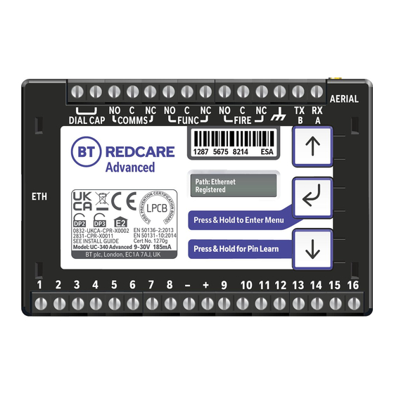
DIAL CAP COMMS COMMS FUNC FUNC 1287 5675 8214 1287 5675 8214 Advanced EN 50136-2:2013 0832-UKCA-CPR-X0002 EN 50131-10:2014 2831-CPR-X0011 SEE INSTALL GUIDE Cert No. 1270g 9-30V 185mA Model: UC-340 Advanced – – Figure 2 – Layout of terminals (not to scale) -
Page 7: Connection Terminals
1287 5675 8214 Connection terminals The screw terminals for the alarm inputs are suitable for use with a standard 3mm blade terminal screwdriver. Power connections Power to the unit is via 2 screw terminals at the centre, with positive to the right nearest Pin 9. The supply voltage range is 9V to 30V. -
Page 8: Outputs
Carry out a survey to establish the best location. If necessary, a selection of high gain and extension aerials can be purchased from the BT Redcare shop at btinstallershop.com... -
Page 9: Programming
Programming Unit initialisation The unit will immediately attempt to connect to the BT Redcare platform over the configured paths. The unit will typically complete path establishment in the following times from power up. 120s 4G/2G 120s Figure 4 – time to commission paths after unit power up Status display The unit clearly displays its status on the OLED. -
Page 10: Signal Strength
Signal strength Signal strength that is: Signal strength that is: • On 2G below -90dBm = X will be displayed • On 4G below -120dBm = X will be displayed • On 2G between -90 and -85, 1 bar will •... -
Page 11: Pin Inputs
Pin inputs Of the 16 alarm pin inputs, all behave as general purposes inputs with the following exceptions: • Pin 1 must be used for Fire alarm when ACK NAK to Pin 13, the unit’s display will show the alarm outputs are used for Fire panels. - Page 12 Keyswitch: Fire output settings: Set or unset the alarm system in conjunction To ensure that the Advanced and Advanced Extra with the BT Redcare app. units can inform the fire alarm panel of status as per the requirements of EN 54, the outputs need to be...
-
Page 13: Configuration
Configuration Pin Learn For speed of installation a single button press Pin Learn is available. All pins to be used should be wired in and all the pins should be in the Press & Hold for Pin Learn non alarm state. No tampers should be active (if wired in) and Pin 4 (open/close) should represent the system being set/closed. -
Page 14: Button Configuration
Button configuration The button configuration mode is entered by holding down the centre configuration button (Enter) for 3s. The unit will then display ‘Configuration’. Configuration Press the Enter button again and the display will show the first menu option. Inputs When in the main menu, each press of will step to the next menu item down. -
Page 15: Main Menu Display
Main menu display Version Exit Configuration Serial Panel Restore Diagnostics Back Inputs Output Type Network Type Defaults DSl/FTTP Mode IP Addr Pin Learn Output Type 1 Subnet Addr Panel Input Sense Output Type 2 Gateway Addr Type Server DNS Addr 1 Back Back Output Type 3... - Page 16 Input Sense The polarity of the pins can manually be configured by the installer. This is in addition to the Pin Learn function described earlier. Example – to configure Pin 4 to be positive removed: Configuration Inputs ation Inputs Sense Pin Learn Press until Inputs Sense 4...
- Page 17 Inputs EOL The alarm inputs (pins) can be set to the following modes: • None – (Alarm and Restore) • EOL (Single end of line mode) – (Alarm, Restore and Cut) • DEOL (Dual End of line mode) – (Alarm, Restore, Cut and Short) Example –...
-
Page 18: Outputs
• RPS – return path signal operates in conjunction with Pin 4. • Fire NAK – Fire pin not acknowledged. Operates in conjunction with Pin 1. • Keyswitch – Set and unset the alarm system in conjunction with the BT Redcare app. 3. Output type 3 (FIRE): •... - Page 19 Example – configure Output 1 (COMMS) for a single path fault Configuration Inputs Output Type Output Type 1 BSIA 175 Output Type 1* Output Type 1* BSIA 175 Single Path Fault Press and hold Notice – Saved! • Access the configuration menu by holding Enter button for 3s. Press the Enter button again, the display will show ‘Pin Learn’.
-
Page 20: Network
Network The programming options under the network sub-menu are: • DSL/FTTP mode – Allows the unit to be changed between dynamic (DHCP client) or Static mode. Default setting is DHCP. The Ethernet port will attempt to obtain an IP address from a DHCP server on the LAN. •... - Page 21 Setting a static IP address, netmask and gateway address If the unit is to be connected to a LAN that requires the unit to have a static IP address (e.g. no DHCP server on the LAN) then this can be configured as follows after setting DHCP to Disabled.
- Page 22 Then use to step to gateway address and use the same process as above to set subnet address ETH Subnet Addr ETH GW Addr * 255.255.255.15 0.0.0.0 ETH IP Addr * ETH GW Addr * 0 0.000.000.000 0 0.000.000.000 Press until correct number First digit highlighted...
- Page 23 10443 Press and hold When used in IP mode, the unit will attempt to establish a connection to the BT Redcare servers by signalling on IP Port 443. For most LANs this will function correctly, but on some advanced LAN configurations the network manager may not allow outgoing access on port 443 but 10443 may have outgoing access.
- Page 24 Web passcode This code is used to set up both the installer and customer app, it can be changed from its default. Configuration Inputs Network ETH DHCP Enabled Press until shows Web Passcode Web Passcode* 12345678 2 345678 Use enter, up and down to change Notice –...
-
Page 25: Serial Connection Panel Type
Serial connection panel type This menu selects the panel connection type for serial connected panels (RS232 or RS485). Settings: • None • Galaxy Classic 485 H (Classic 500/504/512 (RS485)) • Menvier • Texecom 816 (Texecom 412/816/832 • Dimension GD 232 (Galaxy Dimension (RS232 19200 8n2 inv)) 48/96/264/520 (RS232 9600 8n1)) •... -
Page 26: Diagnostics
Open your web browser and enter http://192.168.222.222 You can get the username and password from your BT Redcare account manager. The unit will now have a static IP address of 192.168.222.222 for the duration that the web console is enabled. To access the Web Server a PC needs to be connected to the Ethernet port. -
Page 27: Restore Defaults
• Web Server will automatically exit after 20 minutes. • Web Server can be disabled at any time by the installer. • Web server will revert to disabled if the unit is restarted. • To access the Web Server a PC needs to be connected to the Ethernet port. •... -
Page 28: Web Server
Web server Descriptions below are when directly connecting to the Ethernet port of the unit. The same menu options are available via the web portal or BT Redcare installer app. Log in with the BT username = xxxxx, password = xxxxxxxx... -
Page 29: Main Status Display
Main status display When you first log in you are Status System messages presented with the main status These icons show the status of The system messages box will page. You can return to this the signalling paths and if there scroll though the key messages: page at any time by clicking are any outstanding alarms. -
Page 30: Pins
Pins Pins shows the Name (if changed) and status of each of the pin alarms. OK with a green dot shows the pin is not in alarm and Alarm with the red dot if in alarm. It will also show if a pin is in a cut or short state, with a blue dot and cut or short. -
Page 31: Users
Users This menu allows you to set up additional installers and end customer app access to the unit and change login PIN numbers. To comply with EN 50136-2 Clause 5.2 Access levels, the PIN code access must be set to 6-digits. -
Page 32: Status
The Status sub‑menu shows the status of the IP path. It’s offline and disconnected in the example shown on the left as we have the laptop plugged into the Ethernet port. It also shows the mobile path status, if it’s using 2G or 4G, the signal strength, which SIM and operator. -
Page 33: Gpio
In the GPIO sub‑menu, by You can set up either end of using the dropdown arrows on line (EOL) or dual end of line each section, you can change (DEOL) for each pin as required. any of the pin input status from Mains fail time for Pin 13 can High (positive removed) to Low be adjusted. -
Page 34: Keyswitch
Keyswitch with extended format operate in conjunction with the signalling. BT Redcare App. Any pin can be If using the Keyswitch you will used, but will typically be Pin 4. need to ensure the intrusion... -
Page 35: Panel
The Panel sub‑menu allows selection of the Serial connection for specific panel types. Select the drop down next to Type and you will get a list of panel types. Select the required panel type and connection type and then click Save. ‘Program success’... -
Page 36: Logout
You will need to re-enable the web server through the programming buttons. Web portal and BT Redcare app The device menus are accessible via the BT Redcare web portal and app. When using the web portal and app remotely after installation is completed then the following will apply. -
Page 37: Interconnection Monitoring
Normally open contacts To pin input You will need 1 x 3K3 and 1 x 10K resistors for each PIN with interconnection monitoring. Resistors are available from the BT Redcare installer shop btinstallershop.com 3.3KΩ 1% 10KΩ 1% brown, black, black, red, brown... -
Page 38: What Happens When Pins Are Configured And Wired In This Way
What happens when pins are configured and wired in this way The dual resistor EOL mode is able to detect four states: • Alarm event • Restore • Wire cut • Wire shorted The OLED display will show pin cut The OLED display will show Short 1 through 16 to indicate the wire cut 1 through 16 to indicate the wire... -
Page 39: Roaming Sims
Panel upload Download and Enhanced format signalling (SIA/CID) Remote access to the alarm panel can be achieved using the BT Redcare UDL facility. Additional panel set up information is also available for enhanced format signalling. Contact your BT Redcare representative for further details. -
Page 40: Connection Advice
Example below shows connection via RS 485 to a Galaxy Dimension panel: Figure 9 (not to scale) Connection advice The unit should be connected to the Honeywell Galaxy panel as shown in figure 9, RS485A to A1 and RS485B to B1. Do not use the secondary data line (if your panel has one –... -
Page 41: Alarm List
If intending to use Dial Capture or serial for sending alarms, please confirm beforehand with your ARC that their automation software is capable of differentiating correctly between pin alarms (Advanced or Advanced Extra or Redcare Platform generated alarms) and alarm panel generated ZONE alarms. -
Page 42: Disposal
The manufacturer is not liable for any purely economic loss arising from any use of this equipment. All responsibility and liability in the use of BT Redcare products are assumed by the user. -
Page 43: Glossary
Form 175 as issued by BSIA Subscriber Identity Module (sim card) Greenwich Mean Time Transistor Transistor Logic Internet Protocol Transmit Local Area Network Support For assistance with your BT Redcare installation, please contact the BT Redcare Helpdesk on: 0800 800 628, option 3. -
Page 44: Approvals
Compliance to EN 50136-2: 2013 and EN 50131-10: 2014 EN50136, EN50131, PD6669, PD6662 Advanced is suitable for use in systems installed to conform to PD 6662:2017 at Grade 2/3 (DP2) and environmental class 2. Advanced Extra is suitable for use in systems installed to conform to PD 6662:2017 at Grade 3 (DP3) and environmental class 2. -
Page 45: Appendix
Appendix Example authorisation form For the purposes of on‑going maintenance and configuration Company name Authorises Installer company name Remote access to BT Redcare Next Generation Supervised Premises Transceiver Serial No. number Installed at: premises address Date Signature... - Page 46 Offices worldwide The services described in this publication are subject to availability and may be modified from time to time. Services and equipment are provided subject to British Telecommunications plc’s respective standard conditions of contract. Nothing in this publication forms any part of any contract. ©...
Need help?
Do you have a question about the Advanced and is the answer not in the manual?
Questions and answers