Table of Contents
Advertisement
Quick Links
Advertisement
Table of Contents

Related Manuals for BT Redcare Classic Replacement


Summary of Contents for BT Redcare Classic Replacement
- Page 1 Classic and GSM Replacement Installation Guide...
-
Page 2: Table Of Contents
Contents Contents Troubleshooting Advanced Extra and Connect Introduction Between the Connect and Connect Hub Product description Between the Connect Hub and customer’s router Reset to factory defaults Technical specifications Box contents Appendices Disposal Safety notes Disclaimer Work area safety Support Mounting and wiring Advanced Extra and Connect installation at the alarm panel Mounting the Connect Hub at the customer’s router... -
Page 3: Introduction
Advanced Extra signalling to the customer’s broadband signals via the BT Redcare Advanced Extra unit to the unit using an Ethernet cable. It’s router or network. network to an Alarm Receiving... - Page 4 Colour when set Colour when first Colour when Description up with standard powered up ready for set up configuration Power Blue Blue Blue ETH (Ethernet) Blue Blue Blue Wi-Fi Orange Orange Blue Redcare IoT Link Orange Orange Blue PRESS Cloud Orange Green Blue...
-
Page 5: Technical Specifications
Technical specifications Box contents • Mobile aerial for Advanced Extra Average power figures unit • Advanced Extra signalling unit • Purple and grey aerials for Connect 12V @ 60mA or 24V @ 30mA Connect Hub • Connect Connect Hub 5V @ 500mA •... -
Page 6: Safety Notes
Safety notes Warning: Read all safety warnings and instructions carefully. Failure to heed warnings and follow instructions may result in electric shock, fire risk and/or personal injury. Work area safety • Keep your work area clean, well-lit, • The Connect and Connect Hub and free of obstacles. -
Page 7: Mounting And Wiring
Mounting and wiring Advanced Extra and Connect installation at the alarm panel Assembly of the plug-in adaptor to the Advanced Extra unit If the existing signalling unit is plugged onto the panel, then assemble the plug-in adaptor to the Advanced Extra unit. If not, there’s no need to use the plug-in adaptor. - Page 8 Position the Connect unit and wire to the alarm panel Gently remove the front of the Connect unit and open the moulding by unclipping the four lugs. TO ALARM PANEL TO ADVANCED EXTRA Diagram 3: Removing the front fascia of the Connect unit and connecting it Wire alarm cable from the terminals in the Connect unit to a suitable 12v (60mA) supply in the alarm panel.
-
Page 9: Mounting The Connect Hub At The Customer's Router
Mounting the Connect Hub at the customer’s router Power up the Connect Hub Assemble the Connect Hub aerials There are two different aerials for the Connect Hub, one ringed in purple and one in grey. Make sure they’re screwed to the Connect Hub as per the diagram below. -
Page 10: Set-Up And Initial Configuration
Set-up and initial configuration Here’s how to configure the Advanced Extra unit with Continue through the menu structure pressing buttons as indicated below Connect products. Configuration Inputs Before you start: • Make sure the ETH LED is blue on the Connect Hub - this means your Connect Hub is connected to the customer’s router via Ethernet. - Page 11 Now, press the WPS button on the rear of the Connect Hub until the power Once connected, you should see: LED turns purple/white, and then release – all the LEDs will brighten and then • The IoT, WiFi and Cloud LEDs on the Connect Hub turn blue. darken over a couple of seconds.
-
Page 12: Additional Configuration
Additional configuration WPS button functions Press WPS + PWR LED on then release WPS button = WPS to You can use the WPS button on the rear of the Connect Hub to Connect (see "Set-up and initial put the system into various different configuration modes. configuration"... -
Page 13: Using Wi-Fi Between The Connect Hub And The Customer's Router
1.6. Contact the Redcare technical helpdesk on 0800 800 628 option 3, or Using the IP of the Connect Hub assigned by the customer’s router your Regional Technical Manager, for the default login details. This method is best to use if you’ve temporarily connected an Ethernet cable 1.7. -
Page 14: Disable Or Enable Wi-Fi Between The Connect And Connect Hub
Click WAN WPS button on the settings page, all LEDs on the Connect Hub Status (except power) will brighten and darken during the pairing process. System Status Note: A dial will also be displayed on the settings page to indicate pairing WAN (Wifi) Path in progress WAN Wifi SSID... - Page 15 TO BEGIN... Configuration Inputs PRESS AND HOLD ENTER Network Eth/Connect Ethernet Eth/ Connect* Eth/Connect* Ethernet Connect Press and hold Notice - Eth/Connect Saved! Connect Connect Search Connect Search Scanning CONFIGURATION Now press the WPS Button until just the power LED turns purple/white, then release. WILL APPEAR Completed Connect SSID...
-
Page 16: How To Increase Or Decrease The Brightness Of The Connect Hub Led
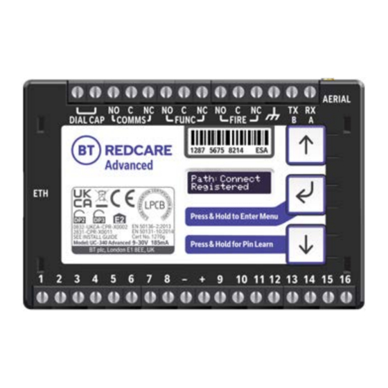
Return to the scrolling OLED display and check that the following is displayed: Path: Connect Registered Connect Strength ] [-58] Then check the Advanced Extra unit is accessible via the app and portal. We recommend at least 1 bar is shown however it may still connect with X displayed. -
Page 17: Troubleshooting
Troubleshooting Check the colour of the status LEDs on the front of the Connect Hub, as this can help you identify the source of any connectivity issue. The correct colours are shown in the right-hand column of the table below. Colour when Colour when set up with Description... -
Page 18: Between The Connect Hub And Customer's Router
• No ports need to be forwarded in the incoming direction. The outgoing TCP connection connects to port 443 or 10443 on the BT Redcare network, so a) You can reset the Connect Hub using the recessed button on the rear of the you would need to allow outgoing access to port 443 or 10443 if you block unit. -
Page 19: Appendices
The manufacturer is not liable for any purely economic loss arising from any use of this equipment. All responsibility and liability in the use of BT Redcare products are assumed by the user. This unit is designed to be used in customer premises. Use of this equipment in... -
Page 20: Support
Support For help with your BT Redcare installation, please contact our helpdesk on: 0800 800 628 (option 3). Offices worldwide The services described in this publication are subject to availability and may be modified from time to time. Services and equipment are provided subject to British Telecommunications plc’s respective standard conditions of contract.
Need help?
Do you have a question about the Classic Replacement and is the answer not in the manual?
Questions and answers