Table of Contents
Advertisement
Quick Links
Advertisement
Table of Contents

Related Manuals for BT Redcare Essential


Summary of Contents for BT Redcare Essential
- Page 1 Essential Installation Guide EN 50136-2: 2013 EN 50131-10: 2014 Cert No. 1270g...
-
Page 2: Table Of Contents
Path status Pin inputs Outputs Configuration Pin Learn Configuration menu programming Button configuration Main menu display Inputs Outputs Network Serial connection panel type Restore defaults Web portal and BT Redcare app Compliance with the user access level requirements of EN 50136... -
Page 3: Introduction
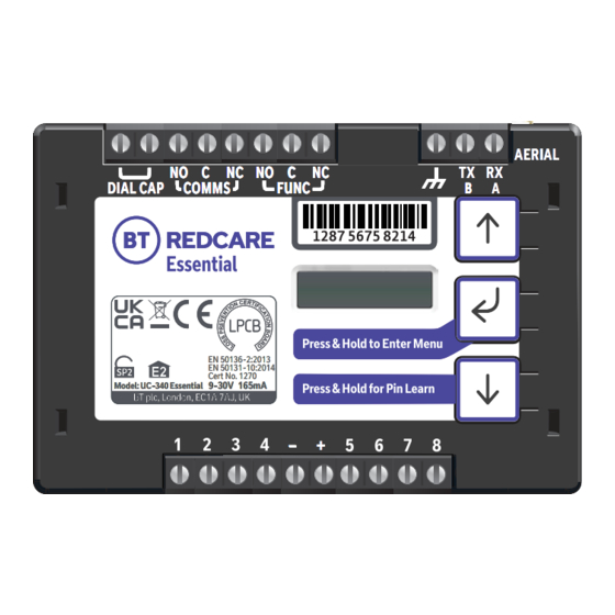
– Figure 1 – Essential unit (not to scale) The BT Redcare Essential unit is a wireless single path, roaming SIM, alarm signalling unit for transmitting alarm signals from a customer’s alarm panel, via the BT Redcare network to an Alarm Receiving Centre (ARC) using pass-through mode of operation. -
Page 4: Specifications
Specifications Size: 95mm x 67mm x 17mm Weight: 73g Power: 9V – 30V Average Max loading (inc. relays Current: Average Normal Operation and dial capture operated) 2G/4G unit @12V 70mA 165mA Alarm inputs: 8 General purpose inputs 1–8. (-0.5V – 30V) Alarm threshold: High >2V, and Low <1.3V Outputs:... -
Page 5: Safety Notes
Safety notes Warning: Read all safety warnings and instructions. Failure to heed warnings and follow instructions may result in electric shock, fire risk and/or personal injury. Work area safety • Keep work area clean, well lit and free of obstacles. •... -
Page 6: Mounting And Wiring
AERIAL DIAL CAP DIAL CAP COMMS COMMS COMMS FUNC FUNC FUNC 1287 5675 8214 EN 50136-2:2013 EN 50131-10:2014 Cert No. 1270 9-30V 165mA Model: UC-340 Essential – Figure 2 – Layout of terminals (not to scale) -
Page 7: Connection Terminals
COMMS COMMS FUNC FUNC FUNC 1287 5675 8214 Essential Connection terminals The screw terminals for the alarm inputs are suitable for use with a standard 3mm blade terminal screwdriver. GUIDE Power connections Power to the unit is via 2 screw terminals at the centre, with positive to the right nearest Pin 5. -
Page 8: Outputs
The aerial should be placed in a vertical position that receives the best wireless coverage. Carry out a survey to establish the best location. If necessary, a selection of high gain and extension aerials can be purchased from the BT Redcare shop btinstallershop.com... -
Page 9: Programming
Programming Unit initialisation The unit will immediately attempt to connect to the BT Redcare platform over the mobile paths. The unit will typically complete path establishment in the following time from power up. 4G/2G 120s Figure 4 – time to commission paths after unit power up The unit sends a ‘System Reset’... -
Page 10: Signal Strength
Signal strength: Signal strength that is: Signal strength that is: • On 2G below -90dBm = X will be displayed • On 4G below -120dBm = X will be displayed • On 2G between -90 and -85, 1 bar will •... -
Page 11: Pin Inputs
Pin 4 is triggered then the output will remain operated for 1s. Keyswitch: Set or unset the alarm system in conjunction with the BT Redcare app. Keyswitch Mode (Visible when output 2 set to Keyswitch) • Momentary – momentary pulse to allow set and unset of alarm panel with customer app. -
Page 12: Configuration
Configuration Pin Learn For speed of installation a single button press Pin Learn is available. All pins to be used should be wired in and all the pins should be in the Press & Hold for Pin Learn non alarm state. No tampers should be active (if wired in) and Pin 4 (open/close) should represent the system being set/closed. -
Page 13: Button Configuration
Button configuration The button configuration mode is entered by holding down the centre configuration button (Enter) for 3s. The unit will then display ‘Configuration’. Configuration Press the Enter button again and the display will show the first menu option. Inputs Inputs When in the main menu, each press of will step to the next menu item down. -
Page 14: Main Menu Display
Main menu display Configuration Version Exit Serial Panel Restore Inputs Output Type Network Diagnostics Back Type Defaults Pin Learn Output Type 1 Input Sense Web Passcode Panel Type Web Server Output Type 2 Inputs EOL Back Back Back Back Back Figure 7 –... - Page 15 Input Sense The polarity of the pins can manually be configured by the installer. This is in addition to the Pin Learn function described earlier. Example – to configure Pin 4 to be positive removed: Inputs ation Configuration Inputs Sense Pin Learn Press until Inputs Sense 4...
- Page 16 Inputs EOL The alarm inputs (pins) can be set to the following modes: • None – (Alarm and Restore) • EOL (Single end of line mode) – (Alarm, Restore and Cut) • DEOL (Dual end of line mode) – (Alarm, Restore, Cut and Short) Example –...
-
Page 17: Outputs
• RPS – return path signal operates in conjunction with Pin 4. • Keyswitch – Set and unset the alarm system in conjunction with the BT Redcare app. Example – configure Output 2 (FUNC) for RPS Configuration Inputs... -
Page 18: Network
Network The programming option under the network sub-menu is: Web passcode This code is used to set up both the installer and customer app. It can be changed from its default: Configuration Inputs Network Web Passcode 12345678 Web Passcode * Web Passcode * 2345678 2345678... -
Page 19: Serial Connection Panel Type
Serial connection panel type This menu selects the panel connection type for serial connected panels (RS232 or RS485). Settings: • None • Dimension GD 232 (Galaxy Dimension 48/96/264/520 (RS232 9600 8n1)) • Dimension GD 485 (Galaxy Dimension 48/96/264/520 (RS485)) • Galaxy G3 232 (G3 48/144/520 (RS232 9600 8n1)) •... -
Page 20: Restore Defaults
5 seconds. This will take you back to the scrolling status display. Web portal and BT Redcare app The device menus are accessible via the BT Redcare web portal and app. When using the web portal and app remotely after installation is completed then the following will apply. -
Page 21: Interconnection Monitoring
To 12V supply input E0L resistor 2 Normally open contacts To pin input Figure 8 You will need 1 x 3K3 and 1 x 10K resistors for each pin with interconnection monitoring. Resistors are available from the BT Redcare installer shop btinstallershop.com... -
Page 22: What Happens When Pins Are Configured And Wired In This Way
3.3KΩ 1% 10KΩ 1% orange, orange, black, brown, brown brown, black, black, red, brown Figure 9 Resistor Item Code Label Colour Code 089446 Red Dot in packet 089447 Blue Dot in packet What happens when pins are configured and wired in this way The dual resistor EOL mode is able to detect four states: •... -
Page 23: Panel Upload Download And Enhanced Format Signalling (Sia/Cid)
Panel Upload Download and Enhanced format signalling (SIA/CID) Remote access to the alarm panel can be achieved using the BT Redcare UDL facility. Additional panel set up information is also available for enhanced format signalling. Contact your BT Redcare representative for further details. -
Page 24: Connection Advice
Example below shows connection via RS 485 to a Galaxy Dimension panel: Figure 10 (not to scale) Connection advice The unit should be connected to the Honeywell Galaxy panel as shown in figure 10, RS485A to A1 and RS485B to B1. Do not use the secondary data line (if your panel has one –... -
Page 25: Alarm List
If intending to use Dial Capture or serial for sending alarms, please confirm beforehand with your ARC that their automation software is capable of differentiating correctly between pin alarms (Essential or Redcare Platform generated alarms) and alarm panel generated ZONE alarms. -
Page 26: Disposal
The manufacturer is not liable for any purely economic loss arising from any use of this equipment. All responsibility and liability in the use of BT Redcare products are assumed by the user. -
Page 27: Glossary
Organic Light Emitting Diode Universal Serial Bus Parallel Input Return Path Signalling (An output that confirms delivery of Pin 4 to the ARC) Support For assistance with your BT Redcare installation, please contact the BT Redcare Helpdesk on: 0800 800 628, option 3. -
Page 28: Approvals
Compliance to EN 50136-2: 2013 and EN 50131-10: 2014 Technical Data: see redcare.bt.com/installer-hub/brochures.html EN50136, EN50131, PD6669, PD6662 Essential is suitable for use in systems installed to conform to PD6662:2017 at Grade 2 (SP2) and environmental class 2. Additional performance parameters: Transmission Time... -
Page 29: Appendix
Appendix Example authorisation form For the purposes of on‑going maintenance and configuration Company name Authorises Installer company name Remote access to BT Redcare Next Generation Supervised Premises Transceiver Serial No. number Installed at: premises address Date Signature... - Page 30 Offices worldwide The services described in this publication are subject to availability and may be modified from time to time. Services and equipment are provided subject to British Telecommunications plc’s respective standard conditions of contract. Nothing in this publication forms any part of any contract. ©...
Need help?
Do you have a question about the Essential and is the answer not in the manual?
Questions and answers