Table of Contents
Advertisement
Quick Links
Advertisement
Table of Contents

Related Manuals for BT Redcare Essential IP


Summary of Contents for BT Redcare Essential IP
- Page 1 Essential IP Installation Guide...
-
Page 2: Table Of Contents
Setting a static IP, netmask and gateway address in Ethernet mode Approvals Setting a static IP, netmask and gateway address in Wi-fi mode App passcode Serial connection panel type Diagnostics Web server using the Essential IP access point Restore defaults... -
Page 3: Introduction
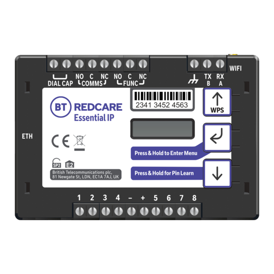
1277 3427 5899 Figure 1 – Essential IP (not to scale) Essential IP is a single path alarm signalling unit for transmitting alarm signals from a customer’s alarm panel, via the BT Redcare network, to an Alarm Receiving Centre (ARC). -
Page 4: Specifications
Specifications Primary path fail reporting 60 mins Alarm transmission category EN standards / PD6669 (UK) SP2 PD6669, ENSO131 (2017) Grade 2 Grade option (Table 10 EN50131 2017) 2A, 2B Environmental class II Information and Substitution security AES256 Size: 95mm x 67mm x 17mm Weight: 73g Power: 9V –... -
Page 5: Mounting And Wiring
Mounting and wiring Removal of cover Remove the top cover by gently releasing each of the four clips on the base of the unit. This can be done by pushing the clips outwards with a screwdriver blade. You shouldn’t need access to the inside of the unit. Mounting Mount the unit inside the alarm panel, or inside a separate powered housing, using the sticky mounting pads supplied. -
Page 6: Connection Terminals
1287 5675 8214 1277 3427 5899 Connection terminals The screw terminals for the alarm inputs are suitable for use with a standard 3mm blade terminal screwdriver. Power connections Power to the unit is via two screw terminals at the centre, with positive to the right, nearest Pin 5. -
Page 7: Outputs
Outputs There are two relay outputs on screw terminals at the top of the unit. Output 1 is COMMS, Output 2 is FUNC. 1277 3427 5899 1287 5675 8214 See further sections on outputs for a detailed explanation. Serial data connections The serial data connection labelled TX, RX, B and A is configurable for RS485 or RS232 connection, depending on the panel. -
Page 8: Programming
If you’re going to connect over wi-fi, the easiest way to set up is using WPS. Power up the unit. Press the WPS button on your customer’s router and within two minutes, press and hold the up arrow marked with WPS on the Essential IP unit. 1277 3427 5899 1287 5675 8214 The display will initially show ‘Discovering’, then ‘Connecting’. -
Page 9: Status Display
Status display The unit clearly displays its status on the OLED. This will differ slightly depending on how the device is connected to the customer router or network. Wired Ethernet In its normal working state, the unit will cycle through its display. Path: Ethernet Service Grade Registered... -
Page 10: Signal Strength
Signal strength • Below -90dBm = X will be displayed. • Between -90 & -85, display will show one bar. • Between -85 & -80, display will show two bars. • Between -80 & -75, display will show three bars. •... -
Page 11: Pin Inputs
Terminal triggered. It will return when an ‘acknowledge’ Power Off Output 1 C <-> NC signal is returned from the BT Redcare platform. The output has a minimum operation time of Path Up and Registered Output 1 C <-> NO one second. -
Page 12: Configuration
You can configure the unit using either the on-board configuration menu driven by the buttons, through the installer app or web portal, connecting a laptop to the Ethernet port or using the Essential IP access point. A minority of sites may need minimal configuration changes at installation, and most of these will be achievable through the button configuration –... -
Page 13: Button Configuration
Button configuration Enter the button configuration mode by holding down the centre configuration button (Enter) for three seconds. The unit will then display ‘Configuration’. 1287 5675 8214 1277 3427 5899 Configuration Press the Enter button again and the display will show the first menu option. -
Page 14: Main Menu Display
Restore Output Type Network Diagnostics Inputs Type Defaults Quick Wifi Eth/Wifi Wifi Setup Press and hold Essential IP’s IP Addr WPS button Pin Learn Wifi SSID Webserver after pressing Subnet Addr Output Type 1 Input Sense Wifi Passcode Panel Type... - Page 15 Input Sense You can also manually configure the polarity of the pins. This is in addition to the Pin Learn function described earlier. Example – to configure Pin 4 to be positive removed: Configuration Inputs ation Input Sense Pin Learn Press until Input Sense 4 Input Sense 1...
- Page 16 Inputs EOL (End of Line mode) You can set the alarm inputs to the following modes: • None – (Alarm and Restore) • EOL (Single End of Line mode) – (Alarm, Restore and Cut) • DEOL (Dual End of Line mode) – (Alarm, Restore, Cut and Short) Example –...
-
Page 17: Outputs
Outputs The two relay outputs can be configured as follows: 1. Output type 1 (COMMS): Keyswitch mode: • Single path fault – operates when path is in fault. • Momentary – allow the FUNC relay, when set to Keyswitch, to be operated remotely via the app 2. -
Page 18: Network
Network The programming options under the network sub-menu are Eth/Wifi. Choose whether you are going to use Ethernet or Wi-fi to connect to the customer’s router – Ethernet is the default option. If Eth is selected, the menu will show: Eth/Wifi Ethernet Ethernet method... - Page 19 Example – to change from DHCP to Static mode: Configuration Inputs Press until shows Network Eth/Wifi Ethernet ETH Method* ETH Method DHCP DHCP ETH DHCP* Notice – Static Saved! • Access the configuration menu by holding the Enter button for three seconds. Press the Enter button again –...
- Page 20 Setting a static IP address, netmask and gateway address If you’re connecting the unit to a LAN that requires the unit to have a static IP address (i.e. no DHCP server on the LAN), set Eth Method to Static then configure as follows: ETH IP Addr ETH Method 0.0.0.0...
- Page 21 Then use to step to gateway address, and use the same process as above to set the subnet address. ETH Subnet Addr ETH GW Addr 255.255.255.15 0.0.0.0 ETH IP Addr* ETH GW Addr* 0 0.000.000.000 0 0.000.000.000 Press until correct number First digit highlighted Press to get to next digit...
- Page 22 DNS Addr 1 Required to convert host names used to contact the server. DNS Addr 2 Alternative DNS addresses – for example 8.8.8.8 or 1.1.1.1 Then use to step to DNS address and use the same process as above to set new DNS addresses. You shouldn’t normally need to change defaults.
- Page 23 You shouldn’t normally need to change defaults. ETH DNS Addr1 ETH DNS Addr 2 192.168.100.001 8.8.8.8 ETH DNS Addr 2* ETH DNS Addr 2* 0 8.008.008.008 0 8.008.008.008 Press until correct number First digit highlighted Press to get to next digit ETH DNS Addr 2* ETH DNS Addr 2* ...
- Page 24 10443 Press and hold The unit will try to connect to the BT Redcare servers by signalling on IP port 443. On most LANs, this will work correctly; on some advanced LAN configurations the network manager might not allow outgoing access on port 443, but may do on port 10443. If this is the case, you can configure the unit to use the alternative port 10443.
- Page 25 Switching to wi-fi using the programming buttons Inputs Configuration Press until shows Network Eth/Wifi Ethernet Eth/Wifi* Eth/Wifi* Wifi Ethernet Press and hold Notice – Saved! You’ll now see the following menu options: Wi-Fi SSID: Here, you can manually enter the SSID of the network you want to connect to, or be shown the SSID of the customer wi-fi network you’re connected to.
- Page 26 Wifi Passcode: This shows the passcode for the wi-fi network you’re connected to, or allows you to enter a passcode. Wifi Passcode Wifi Passcode* If up arrow is used here, ‘a’ will be first character displayed Wifi Passcode* Wifi Passcode* ...
- Page 27 Wifi Search: starts a search for all available wi-fi networks. Wifi Search Notice Scan Refresh Done! Press and Hold till Wifi Search Wifi SSID Scanning... Completed You can see the results of this search by pressing to go to Wi-Fi List. Wifi List Wifi Search Completed...
- Page 28 Wifi Method: This allows the unit to be changed between Dynamic (DHCP client) or Static modes. The default setting is enabled. The wi-fi modem will try to obtain an IP address from a DHCP server on the LAN. • IP address: shows current IP address but can also be configured for a static IP address.
-
Page 29: Setting A Static Ip, Netmask And Gateway Address In Wi-Fi Mode
Setting a static IP address, netmask and gateway address in Wi-fi mode If you’re connecting the unit to a LAN that requires the unit to have a static IP address (i.e. no DHCP server on the LAN), set Wifi Method to Static then configure as follows: Wifi IP Addr Wifi Method 0.0.0.0... - Page 30 Then use to step to gateway address and use the same process as above to set subnet address. Wifi Subnet Addr Wifi GW Addr 255.255.255.15 0.0.0.0 Wifi IP Addr* Wifi GW Addr* 0 0.000.000.000 0 0.000.000.000 Press until correct number First digit highlighted Press to get to next digit...
- Page 31 Then use to scroll to DNS Address and use the same process as above to set new DNS addresses. You shouldn’t normally need to change any defaults. Wifi GW Addr Wifi DNS Addr 1 192.168.1.254 1.1.1.1 Wifi DNS Addr 1* Wifi GW Addr* ...
- Page 32 You shouldn’t normally need to change any defaults. Wifi DNS Addr 1 ETH DNS Addr 2 192.168.100.001 8.8.8.8 Wifi DNS Addr 2* Wifi DNS Addr 2* 0 8.008.008.008 0 8.008.008.008 Press until correct number First digit highlighted Press to get to next digit Wifi DNS Addr 2* Wifi DNS Addr 2* ...
- Page 33 10443 Press and hold The unit will try to connect to the BT Redcare servers by signalling on IP port 443. On most LANs, this will work correctly; on some advanced LAN configurations the network manager might not allow outgoing access on port 443, but may do on port 10443. If this is the case, you can configure the unit to use the alternative port 10443.
-
Page 34: App Passcode
App passcode Use this code to set up both the installer and customer app. You can change it from its default. Inputs Configuration Press until shows Network Eth/Wifi Ethernet If set to Wifi, Eth/Wifi will show ‘Wifi’. Press until shows App Passcode App Passcode ... - Page 35 Example – changing the unit to connect to a Texecom Premier Elite panel via RS485 Inputs Inputs Configuration Press until shows Serial Panel Type Panel Type None Panel Type* Panel Type* Texecom Premier None Press until shows Press and hold Notice –...
-
Page 36: Diagnostics
You can get the username and password from your BT Redcare account manager. The unit will have a static IP address of 192.168.222.222 while the web console is enabled. To access the web server via the Ethernet port, connect a PC. If you’re using an Ethernet switch to allow connectivity to the customer’s network and your laptop, the unit... -
Page 37: Web Server Using The Essential Ip Access Point
When the web server is enabled, search for wi-fi networks on your smart device or laptop. You’ll identify the Essential IP access point by its name, which will be in the format Redcare-XXXX – where XXXX is the last four digits of serial number of the unit. -
Page 38: Restore Defaults
Restore defaults You can use the Restore defaults option on the menu to set the unit back to its factory defaults, and reset all settings to their standard values. Example – setting the unit back to factory default: Inputs Inputs Configur Configuration Restore Defaults... -
Page 39: Web Server
Web server Sign in with your BT username and password. This is available from the BT Redcare Technical Helpdesk, or your Redcare account manager. The menu The menu bar on the left hand side can take you Should you need to make any changes in the to any of the menu options described below. -
Page 40: Main Status Display
Main status bar When you first sign in, you’ll be presented with the main status page, as above. You can return to this page at any time by clicking Main on the menu bar. The status page shows the user operated outputs. You can operate Output 2 (FUNC) – which can be renamed in the settings menu –... -
Page 41: Status Bar
Status bar The status bar will indicate if there are any alerts on the system. You can close it down by clicking X. Main Alarm status The display here will show ‘Alert’ or ‘Good’. Click on the ‘View status of all pins’... -
Page 42: System Status
Note that if you’re connected to the web server via the Ethernet port on the device or via the Essential IP access point, you will lose connection to the platform. The information you get from the advanced system info drop-down will depend on your connection method. -
Page 43: Events
Events This menu shows the most recent events recorded by the system. By clicking on the drop-down you can filter events by type – for example, Alarms, System, Configuration or Connection. Settings... -
Page 44: The Settings Sub-Menu
The Settings menu has sub- menus that let you program the unit. The first item on the sub-menu is Details, which gives you device details, including MAC addresses and firmware version. Use the drop-down to access the sub-menus. The Status sub-menu shows the status of the IP path. -
Page 45: Network
The Network sub-menu allows you to change the interface between wi-fi or Ethernet, change from DHCP to Static, search and select wi-fi networks, and set up your app passcode. To change from DHCP to a Static IP address when using an Ethernet connection, click on the drop-down arrow which will then show the choices DHCP and... - Page 46 Clicking WPS will start a WPS session. Press WPS on the customer’s hub within two minutes. This will disconnect the Essential IP access point and, if successful, connect to customer’s hub and the Redcare platform Clicking Search will initiate a wi-fi network search.
-
Page 47: Users
In the Users sub-menu, you can add new users and edit existing users. In edit mode, you can change the username, PIN and type of user. You can also delete a user. When you click ‘Add a new user’ you’ll see the screen on the left. Enter the required information and click ‘Add user’. -
Page 48: Gpio
In the GPIO sub-menu, you can change any pin input status from High (positive removed) to Low (positive removed) by using the drop-down arrows on each section. You can set up either end of line (EOL) or dual end of line (DEOL) for each pin as required. - Page 49 In this example, we show Pin 8 as Active High, with DEOL monitoring. Output 2 is set to operate as a User output (operated by the customer via the app). Make all your changes to the pin inputs and outputs, then click the save button to store them in the unit.
-
Page 50: Name Editor
The Name Editor sub-menu allows you to add names to the pin inputs, which will then show up on the customer app and notifications. You can choose a description for the User relay outputs. Click Save after you’ve entered all the information. -
Page 51: Panel
The Panel sub-menu allows selection of the Serial connection for specific panel types. Select the drop down next to Type and you will get a list of panel types. Select the required panel type and connection type and then click Save. ‘Program success’... -
Page 52: Keyswitch
In the Keyswitch sub-menu, you can set up a keyswitch to operate in conjunction with the BT Redcare App. Any pin can be used, but will typically be Pin 4. It can be Latched or Momentary and armed low or high. - Page 53 Select the open/close pin to use for the Keyswitch. This is usually Pin 4. Select the state of the pin for armed (set) and disarmed (unset). The Alarm option for Input Mode allows a Keyswitch to operate with extended format signalling.
-
Page 54: Reports
The Reports sub-menu allows you to set up a number of email addresses that could receive emails on the various options. E.g. Alarms and System messages. In the Ultrasync sub-menu, DO NOT alter any settings. -
Page 55: Reset Defaults
The Default sub-menu gives you the option to restore the unit to factory settings by clicking Reset to Defaults. Logout Clicking Logout will take you back to the sign-in screen. Should the web server enablement time out, you won’t be able to save changes –... -
Page 56: Interconnection Monitoring
Normally open contacts To pin input You will need 1 x 3K3 and 1 x 10K resistors for each pin with DEOL interconnection monitoring. These are available from the BT Redcare installer shop btinstallershop.com 3.3KΩ 1% 10KΩ 1% orange, orange, black, brown, brown... -
Page 57: What Happens When Pins Are Configured And Wired In This Way
Above, example Short on Pin 8. Panel Upload Download and Enhanced format signalling (SIA/CID) You can have remote access to the alarm panel using the BT Redcare UDL facility. Additional panel set-up information is also available for enhanced format signalling. -
Page 58: Connection Advice
Example below shows connection via RS 485 to a Galaxy Dimension panel: Figure 8 (not to scale) Connection advice The unit should be connected to the Honeywell Galaxy panel as shown in figure 8 – RS485A to A1 and RS485B to B1. Do not use the secondary data line (if your panel has one –... -
Page 59: Alarm List
If intending to use dial capture or serial for sending alarms, please confirm beforehand with your ARC that their automation software is capable of differentiating correctly between pin alarms (Essential IP or Redcare Platform generated alarms), and alarm panel generated zone alarms. -
Page 60: Disposal
The manufacturer is not liable for any purely economic loss arising from any use of this equipment. All responsibility and liability in the use of BT Redcare products are assumed by the user. -
Page 61: Glossary
Greenwich Mean Time Transistor Transistor Logic Internet Protocol Transmit Local area Network MMCX Micro Miniature Coaxial Connector Support For assistance with your BT Redcare installation, please contact the BT Redcare Helpdesk on: 0800 800 628 – select option 3. -
Page 62: Approvals
BT Redcare, BT Plc 81 Newgate Street London EC1A 7AJ 2020 EN50136, EN50131, PD6669, PD6662 Essential IP is suitable for use in systems installed to conform to PD 6662:2017 at Grade 2 ( SP2) and environmental class 2. Additional parameters: Description Transmission Time... - Page 63 Offices worldwide The services described in this publication are subject to availability and may be modified from time to time. Services and equipment are provided subject to British Telecommunications plc’s respective standard conditions of contract. Nothing in this publication forms any part of any contract. ©...
Need help?
Do you have a question about the Essential IP and is the answer not in the manual?
Questions and answers