Table of Contents
Advertisement
Quick Links
Advertisement
Table of Contents

Subscribe to Our Youtube Channel
Related Manuals for multicomp pro MP780002


Summary of Contents for multicomp pro MP780002
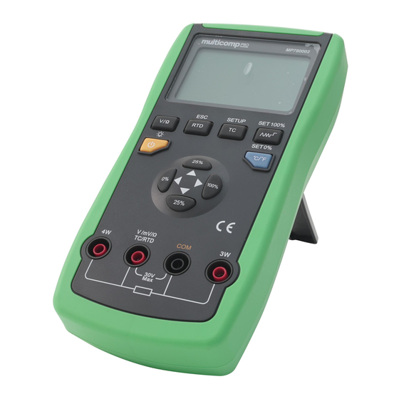
- Page 1 Temperature Calibrator Model No. MP780002...
-
Page 2: Important Safety Information
IMPORTANT SAFETY INFORMATION Read all instructions before using the appliance and retain for future reference. • Please follow all safety operation instructions. • Check the test leads, probes and case insulation before using. If you find any breakage or abnormality, or you consider the device is broken, stop using the device immediately. - Page 3 Power ON/OFF button Mode button V/Ω RTD output button Thermocouple output mode button SLOPE/STEP mode button C/F Temperature scale button Value setting buttons Test lead connection terminals FUNCTIONS Source • Connect the red test lead to V terminal, black to COM terminal, and connect the red probe to the positive terminal of voltmeter, black to negative terminal.
- Page 4 • Briefly press the UP or DOWN (25%) value buttons to add or subtract 1 for the value above the underline (the value is automatically carried and the position of the underline remains unchanged) and press LEFT (0%) or RIGHT (100%) to change the position of the underline.
-
Page 5: Operation
OPERATION Voltage Output • Short press V/Ω and select voltage output, LCD displays ‘mV’ unit, then select the corresponding range as required. • Connect the red test lead to V terminal, black to COM terminal. • Connect the red probe to positive end of the voltmeter, black to negative end of the voltmeter. - Page 6 Simulating Thermocouples • Connect the calibrator output to the instrument being measured with thermocouple wires and simulate the thermocouple as follows: • Short press T/C button to choose the thermocouple function, LCD will display C unit. Keep pressing this button to select the required thermocouple type ( C or •...
-
Page 7: Advanced Applications
Simulating Resistance Temperature Detectors (RTD) • Connect the calibrator to the instrument being measured according to the figure as shown, and simulate the RTD as follows: • Press RTD button to select the RTD type. • Connect the thermocouple wires to the calibrator as shown above: connect the red test lead to TC terminal, black to COM terminal. - Page 8 Output Functions 0% value 100% Value WRe526 2000.0 WRe325 2000.0 Pt100 500.0 Pt1000 400.0 Cu50 150.0 Cu100 150.0 • These factory settings may not be suitable for your work, you can reset them according to your requirements so that you can use the step or ramp output function and get the percentage display.
-
Page 9: Specifications
SPECIFICATIONS • All specifications are based on a one year calibration period and applied to a working temperature range of +18 C~+28 C unless otherwise specified. All specifications are obtained after a 30 minute period of operation. Display count: 200000 Range: manual Operating temperature:... - Page 10 Temperature Thermocouple Range Max output range Resolution Accuracy ±(% reading + digits) -200 C/0.1 c~1200 -200 C/0.1 c~1370 -200 C/0.1 c~400 -200 C/0.1 c~950 c~500 c~1750 c~500 c~1750 -600 c~800 c~1000 1000 c~1800 -200 C/0.1 c~1300 Wre325 c~2000 C/0.1 Wre526 c~2300 C/0.1 The error in this table does not include the error of cold junction temperature...
-
Page 11: Maintenance
MAINTENANCE Warning: Before opening the rear cover or the battery cover, power the instrument down and remove the test leads from any device or circuit under test and remove the test leads from the input terminals • If the low battery symbol illuminates on the LCD, this indicates that the battery power is less than 20%. - Page 12 INFORMATION ON WASTE DISPOSAL FOR CONSUMERS OF ELECTRICAL & ELECTRONIC EQUIPMENT. These symbols indicate that separate collection of Waste Electrical and Electronic Equipment (WEEE) or waste batteries is required. Do not dispose of these items with general household waste. Separate for the treatment, recovery and recycling of the materials used. Waste batteries can be returned to any waste battery recycling point which are provided by most battery retailers.
Need help?
Do you have a question about the MP780002 and is the answer not in the manual?
Questions and answers