Table of Contents
Advertisement
Quick Links
TDR CABLE TESTER KIT
MP780994
Contents
VII.POE Mode
VIII.Tone Mode
8.2 Receiver (for MP780994 KIT only) ---------------------------------------------------- 16
IX. Calibrating Length Measurements (Only for test mode) ---------------------------- 18
9.1 Setting the NVP to a Specified Value ------------------------------------------------ 18
9.2 Determining a Cable's Actual NVP ---------------------------------------------------- 19
3
3
4
4
5
6
6
12
14
15
15
19
19
19
20
20
20
20
20
2
Advertisement
Table of Contents

Related Manuals for multicomp pro MP780994


Summary of Contents for multicomp pro MP780994
-
Page 1: Table Of Contents
VII.POE Mode VIII.Tone Mode 8.1 Tone Mode Display 8.2 Receiver (for MP780994 KIT only) ---------------------------------------------------- 16 IX. Calibrating Length Measurements (Only for test mode) ---------------------------- 18 9.1 Setting the NVP to a Specified Value ------------------------------------------------ 18 9.2 Determining a Cable’s Actual NVP ---------------------------------------------------- 19 X. -
Page 2: Overview
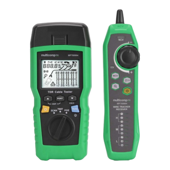
III. Safety Information To avoid fire, electric shock or personal injury, please follows: MP780994 KIT is a handheld TDR cable tester, suitable for copper cables (CAT 5E, Do not open the casing, there is no any user-serviceable parts inside. CAT 6,CAT 6A or CAT 8) used to detect and diagnose wiring condition of twisted pair and... -
Page 3: Display Features Mp780994
VI. Testing Mode V. Display Features (MP780994) 6.1 Testing Twisted-Pair Cabling 6.1.1 Cabling Test (1) Turn on the tester, and set the knob to "TEST", then press "PORT" to select RJ45 10 11 port. (2) Connect tester and wiremap adapter to the cabling, the test runs continuously until you change modes or turn the tester off. - Page 4 6.1.2.4 Crossed Pairs 6.1.2.2 Short on Twisted Pair Cabling Figure 6.5 shows that 1, 2 and 3, 6 are crossed. The pin numbers flash to indicate the fault. Figure 6.3 shows a short between wires 5 and 6, the shorted wires flash to indicate the Detection of crossed wires requires a far-end adapter.
- Page 5 6.1.2.8 Voltage Detection 6.1.2.6 Ethernet Port Detected Figure 6.9 shows that the tester detects cable voltage. Figure 6.7 shows that the tester detects Ethernet port. If the measured cable is live and its voltage is greater than or equal to 10V, the tester The tester cannot measure the length if the port does not produce reflections.
-
Page 6: Testing Coaxial Cabling
6.1.2.11 Connecting to Telephone Networks in Bus Topologies 6.1.2.10 Connecting to Telephone Networks Wired in Star Topologies Telephone cables wired in a bust topology (Figure 6.12) connect the wall outlets in series. Telephone cables wired in a star topology (Figure 6.11) are connected together at a bridge In this topology, you measure the length from the last outlet to the wiremap adapter. - Page 7 6.2.2 Typical Testing Results 6.2.2.4 Voltage on Coaxial Cabling Figure 6.17 shows that the symbol “ ” appears if the coaxial cable is live and its voltage 6.2.2.1 Results for a Good Coaxial Cable is greater than or equal to 10V. Figure 6.14 shows a good coaxial cable 63.2m and terminated with far-end adapter Figure 6.14 Coaxial Results Figure 6.17 Voltage on Coaxial Cabling...
-
Page 8: Tone Mode Display
8.1 Tone Mode Display 8.2.1 Features With the support of MP780994 tester, the receiver can achieve multiple functions such as (1) Turn on the tester, then set the knob to “SCAN”. In tone mode, the default display is locating and isolating cables by adjusting sensitivity, twisted-pair cable tracking, coaxial shown in Figure 8.1.a. -
Page 9: Calibrating Length Measurements (Only For Test Mode)
40V (AC), the receiver makes beep sound and the NCV indicator light flashes synchronously. (2) Set MP780994 tester to “SCAN” mode, press “PORT” to select RJ45 port. Short (2) Flashlight: Press the flashlight button to enable the flashlight function separately. -
Page 10: Determining A Cable's Actual Nvp
XIII. Other Functions 9.2 Determining a Cable’s Actual NVP 13.1 Low battery indication (1) Hold down “ ”, “ ” and “ ” at the same time to enter NVP setting mode. (2) To set the NVP of coaxial port, please press “PORT. Please replace the battery when the symbol “...
Need help?
Do you have a question about the MP780994 and is the answer not in the manual?
Questions and answers