
Subscribe to Our Youtube Channel
Related Manuals for multicomp pro MP780905


Summary of Contents for multicomp pro MP780905
- Page 1 User Manual Digital Sound Level Meter with USB Part Number: MP780905 Newark.com/multicomp-pro Farnell.com/multicomp-pro sg.element14.com/b/multicomp-pro Page <1> 12/07/22 V1.0...
- Page 2 Important Safety Information Read these instructions carefully before use and retain for future reference. • Please operate according to this manual, otherwise the protection provided by the device will be impaired or fail. • C heck the condition before using. If you find any cracking, breakage, damage or abnormality, or you consider the device broken, stop using the device immediately • Do not store or operate the instrument at high temperature and high humidity environment. • Keep microphone dry and avoid severe vibration. • Replace the batteries as soon as the low battery indicator appears on the display. • Remove dead batteries from the meter or if it is not going to be used for a long time. • Never mix old and new batteries together, or different types of batteries. • Never dispose of batteries in a fire, or attempt to recharge ordinary batteries. • Before replacing the battery, turn off the sound level meter. • To prolong battery life turn off the sound level meter after use. What’s Included • Sound level meter including battery. • ...
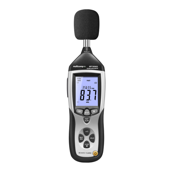
- Page 3 2. LCD display. 3. REC button. DATALOGGER function: Press “REC” button after powering on, the display will show “REC” to start data recording. Press the button again to exit the record mode. Note: In order to avoid data error, please don’t power it off under REC condition, when the REC function is inactive then the meter can be powered off. Adjusting DATALOGGER response: Press and hold the backlight button and power the meter on. Press ’LEVEL’ button to adjust memory time, press ‘HOLD’ button to hold the setup. Data zero function: Press and hold the button and power the meter on, then release the button when the display shows ’CLR’, which indicates that the data in DATALOGGER has been deleted. 4. SETUP button. Press and hold SETUP and power the meter on. When ‘TIME’ displays on screen release the button. Use the LEVEL button to make adjustments and HOLD to store them and then the SETUP button to move to the next setting. USB communications setting: Turn on the meter, connect the meter to the PC via USB lead, choose the software COM port, then press ‘SETUP’, ‘O‘ disappears from the display to indicate auto power off is disabled and that the USB data is transmitting.
- Page 4 12. External 9V DC power supply connector. 3.5mm socket internal dia 1.35mm +ve connection. 13. USB interface. USB signal output at 9600bps serial interface. 14. AC/DC signal output earphone socket. AC: Output voltage: 1Vrms corresponding to each range step. Output impedance: 100Ω. DC: Output voltage: 10mV/dB. Output impedance: 1kΩ. 15. Calibration potentiometer. For external standard level calibration adjustments. 16. Tripod mounting screw. 17. Battery cover. 18. Microphone. 1/2” electret condenser microphone. Operation • T o achieve more accurate measurement, use an extension cable to separate the microphone from the main body so that the effect of unexpected sound reflection can be eliminated.
- Page 5 DATALOGGER Function Installing the software • Start windows and Insert the CD into the CD-drive. • Run SETUP.EXE installation program in file DISK1 and install the application software to your preferred directory. • Reboot Windows then connect the sound level meter to the PC using the supplied USB cable. • If prompted to install drivers for the device install the CP210XWIN driver. • The PC will now detect the new hardware and load the driver and create a new COM port. • Start the application software and search for the new COM port. • Press SETUP button and the meter is now ready to transfer data to the computer. • Enter the menu REAL TIME/SETUP to set the monitoring data (data volume, response, monitoring time). • The computer will read the memory data in the meter. Specifications Frequency Range : 31.5Hz to 8kHz Measuring Level Range : 30 to 130dB Frequency Weighting : A/C Microphone : 1/2 inch electret condenser microphone Display : LCD 4 digits Resolution : 0.1dB Display Up data : 0.5 sec. Time Weighting : Fast: 125ms; Slow: 1s Level Ranges ...
- Page 6 Auto Power Off : Auto shut down after approx. 15 minutes of inactivity. Operating Temperature : 0°C to 40°C (32°F to 104°F) Operating Humidity : 10 to 90% RH Altitude : up to 2000 metres Storage Temperature : -10°C to 60°C (14°F to 140°F) Storage Humidity : 10 to 75% RH Power Supply : One 9V battery, 006P or IEC 6F22 or NEDA 1604 Power Life : About 50hrs (Alkaline Battery) Dimensions : 210mm(L) × 55mm(W) × 32mm(H) Weight : 230g (8.11oz) (Including Battery) Maintenance Changing the battery To install or change the 9V battery, open the battery compartment. Replace only with the same type of battery. Cleaning the casing Wipe using a damp cloth or sponge. Do not use solvents as these may damage the casing. Do not immerse in water. INFORMATION ON WASTE DISPOSAL FOR CONSUMERS OF ELECTRICAL & ELECTRONIC EQUIPMENT T hese symbols indicate that separate collection of Waste Electrical and Electronic Equipment (WEEE) or waste batteries ...
Need help?
Do you have a question about the MP780905 and is the answer not in the manual?
Questions and answers