Table of Contents
Advertisement
Quick Links
Advertisement
Table of Contents

Related Manuals for Swegon AQUA Link


Summary of Contents for Swegon AQUA Link
- Page 1 AQUA Link Installation, use and mantenaince manual 20121205...
-
Page 3: Table Of Contents
Index 1. GENERAL INFORMATION ....................4 TECHNICAL FEATURES ................... 4 THE SERIES ......................4 ACCESSORIES ......................6 FIELD OF APPLICATION ................... 6 2. INSPECTION, UNPACKING, TRANSPORT ..............7 INSPECTION ......................7 UNPACKING ......................7 LIFTING AND TRANSPORT ..................7 POSITIONING ......................9 ANTI-VIBRATION SUPPORTS (OPTION) ............... -
Page 4: General Information
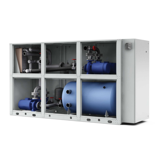
1.2 THE SERIES AQUA Link The AQUA Link hydraulic equipment series for indoor or outdoor housing is available in various sizes in combination with a chiller whose total rated power varies from 90 to 300 kW. As for the utilities side, the sizing of the unit is designed to allow it to be combined to systems providing for a subdivision in... - Page 5 Power to UTA Power to Chilled Beams NO GLYCOL VERSION Power to UTA Power to Chilled Beams For specifications, available models, and technical data please refer to the AQUA Link TECHNICAL BOOKLET. CONFIGURATIONS EXAMPLE OF A CONFIGURATION AQUA Link 1P 1PM...
-
Page 6: Accessories
The model, serial number, features, power supply voltage, etc., are reported on the labels applied to the machine 1.3 ACCESSORIES primary circuit double standard pump secondary circuit standard pump (single or double in line with the primary circuit one/s) primary circuit high head pressure pump (single or double) secondary circuit high head pressure pump (single or double in line with the primary circuit one/s) model for outdoor installation panelled model for indoor installation... -
Page 7: Inspection, Unpacking, Transport
The installer must protect any connecting pipe sections between the indoor system and AQUA Link For temperatures below -15° C (i.e. for glycol perce ntages between 30% and 40%) a series of heating elements designed to protect the main parts (pump motors, valve bodies...) and the electrical control board must be set up... - Page 8 Figure 1: Unit lifting operation Warning: During all lifting operations, make sure the unit is firmly secured to prevent it from tipping over or falling. The lifting equipment, ropes and harnesses must be chosen by personnel having appropriate skills who are able to assume all responsibilities related to their use. The machine is balanced.
-
Page 9: Positioning
2.4 POSITIONING The following must be taken into account when choosing the unit place of installation and making relevant connections: – size and origin of the hydraulic piping; – location of the power supply; – accessibility for maintenance or repair operations; –... -
Page 10: Anti-Vibration Supports (Option)
The slab must be: – made in suitable foundation with a height of about 15-20 cm above the surrounding land, – supplied with a cork gasket properly sealed along the perimeter, – flat, horizontal and able to support 150% of the operating weight of the machine. –... -
Page 11: Installation
3. INSTALLATION 3.1 SPACES FOR INSTALLATION The unit is made grouping all connections to the outdoor hydraulic circuit on a single side. Check that the positioning of the unit allows easy access to that side and the electric control board. Comply with the clearances as shown on the dimensional drawing, and ensure they are calculated allowing easy access to internal components in case of maintenance. - Page 12 – expansion tank and automatic valves to keep the system pressure and compensate for thermal expansion – check that the automatic glycol loading in the circuit is carried out with a mixture of the same concentration as that already present. Otherwise you may risk the hydraulic circuit freezing with serious damage to the parts concerned. –...
- Page 13 Figura 5: schema idraulico dell'unità con glicole (tank fitted as standard) LEGENDA SF = Valvola di sfiato – Bleed valve BP = Trasd.di pressione – Pressure transducer SB = Serbatoio d’accumulo – Storage tank EL = Elettropompa – Electric pump RB = Rubinetto –...
-
Page 14: Water Content Of The System
GLYCOL UNITS An on-board AQUA Link tank is always included as part of the standard supply of these units. The associated chiller must, in turn, be selected with an on-board tank. This choice is based on the possibility of exploiting a complete system that is not dependent on external accessory elements. -
Page 15: Electrical Connections
3.6 CHECKS AQUA Link is not equipped with a completely independent control but is provided with a control module (IQ-nomic) controlled by a signal from the module (IQ-nomic) connected to the Gold and from the (All Year Comfort) module that... -
Page 16: Safety Measures
The connection between different units is created by connecting control modules (IQ-nomic) together as shown in wiring diagrams. The AQUA Link hydraulic module is equipped with inverter technology to adjust the rotation speed of the pumps contained in 4. SAFETY MEASURES The machine complies with Directives 2006/42/EC, 2004/108/EC, 2006/95/EC, 97/23/EC and applicable Technical Standards as specified in the Declaration of Conformity which is an integral part of this manual. -
Page 17: Installation In Areas With Explosive Atmospheres
4.3 INSTALLATION IN AREAS WITH EXPLOSIVE ATMOSPHERES The units do not fall within the scope of the 94/9/EC directive – Presidential Decree n. 126 dated 23/3/98 no. 126, therefore they are not designed for installation in potentially explosive atmospheres. Contact the manufacturer for any adjustments/solutions. 4.4 PROTECTIVE DEVICES The machine is equipped with appropriate technical means to protect people from the hazards that cannot be reasonably eliminated or adequately reduced through design. -
Page 18: Commissioning
5. COMMISSIONING 5.1 PRELIMINARY CHECKS – Check that the electric connection has been performed correctly and that all clamps are tightly fastened. – Check that the voltage of line terminals meets specifications. If voltage is subject to frequent changes, contact our technical department to select appropriate protections. -
Page 19: Operation
The two-way valve internal to AQUA Link has the aim to adjust the temperature of the water sent to the circuit of the chilled beams, a value established by the All Year Comfort control. The 0-10 V signal that drives this valve must come from a temperature probe installed on the flow of the secondary circuit (see par. -
Page 20: Regular Maintenance And Inspections
Check there are no water leaks on the hydraulic circuit joints Monthly Check the filling of the hydraulic circuit Monthly Clean the Y filter on the hydraulic circuit located outside the AQUA Link module (not supplied Monthly as standard) Ensure that the noise emitted by the machine is regular Every 4 months 7.3 PROTECTING THE ENVIRONMENT...
Need help?
Do you have a question about the AQUA Link and is the answer not in the manual?
Questions and answers