Inficon HLD6000 Translation Of The Original Operating Instructions
Leak detector
Hide thumbs
Also See for HLD6000:
- Installation manual (76 pages) ,
- Original operating instructions (76 pages)

Related Manuals for Inficon HLD6000


Summary of Contents for Inficon HLD6000
- Page 1 Translation of the original operating instructions HLD6000 Leak detector Catalog No. 510-025, 510-027, 510-127, 510-028, 510-128 From software version kinb43en1-05-(2107) 1.24 or higher (Operating unit)
- Page 2 INFICON GmbH Bonner Strasse 498 50968 Cologne, Germany...
-
Page 3: Table Of Contents
5.3.2 Using a water conservation sniffer tip .................. 30 5.3.3 Using flexible sniffer tip ....................... 30 5.3.4 Using an extension hose for a sniffer tip.................. 31 5.4 Using calibration leaks.......................... 32 5.5 Connecting to the power supply system .................... 32 5.6 Using a USB stick ........................... 32 HLD6000-Operating-instructions-kinb43en1-05-(2107) - Page 4 6.3.3 Setting up the sniffer probe...................... 46 6.3.4 Setting up the gas for the SMART sniffer line................ 46 6.3.5 Verifying R290 with the sniffer line for R600a/R290 .............. 48 6.3.6 Calibrating........................... 48 6.3.6.1 Time and type of calibration .................... 48 HLD6000-Operating-instructions-kinb43en1-05-(2107)
- Page 5 8.2 Sniffer line............................... 75 8.2.1 Replacing the filter holder (all sniffer lines) ................. 76 8.2.2 Replacing the filter block (all sniffer lines)................... 76 8.3 Sending for repair or maintenance ...................... 76 8.4 Maintenance table .......................... 77 9 Decommissioning ............................ 78 9.1 Disposing of the device........................... 78 HLD6000-Operating-instructions-kinb43en1-05-(2107)
- Page 6 9.2 Sending in the device .......................... 78 10 Appendix................................. 80 10.1 Accessories and spare parts ........................ 80 10.2 Menu path............................... 82 10.2.1 Diagnosis ............................ 82 10.2.2 Settings ............................ 82 10.2.3 Information .......................... 83 10.3 CE Declaration of Conformity ......................... 84 10.4 RoHS .............................. 85 Index................................ 86 HLD6000-Operating-instructions-kinb43en1-05-(2107)
-
Page 7: About This Manual
Imminent hazard resulting in death or serious injuries WARNING Hazardous situation resulting in potential death or serious injuries CAUTION Hazardous situation resulting in minor injuries NOTICE Hazardous situation resulting in damage to property or the environment HLD6000-Operating-instructions-kinb43en1-05-(2107) 7 / 90... -
Page 8: Safety
The device is a leak detector for sniffer leak detection. With the device you locate and quantify leaks on test objects. The HLD6000 sniffs for different gases depending on which sniffer line is connected. The following sniffer lines are available: •... -
Page 9: Owner Requirements
The measuring instrument was built according to the state-of-the-art and the recognized safety regulations. Nevertheless, improper use may result in risk to life and limb on the part of the user or third parties, or damage to the unit or other property may occur. HLD6000-Operating-instructions-kinb43en1-05-(2107) 9 / 90... - Page 10 Exposure of the eyes to LED light can lead to lasting eye damage. exposure to light • Do not look into the LEDs of the sniffer handle from a short distance or for longer periods of time. 10 / 90 HLD6000-Operating-instructions-kinb43en1-05-(2107)
-
Page 11: Shipment, Transport, Storage
Operating manual Interface description USB stick with instructions, software The scope of delivery of the HLD6000 with the order numbers 510-027 and 510-127 also includes a calibration leak. ► Check the scope of delivery of the product for completeness after receipt. -
Page 12: Description
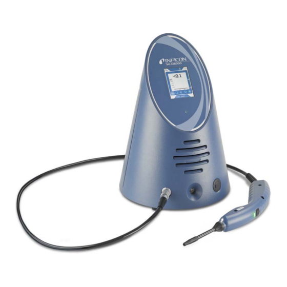
4 Description 4.1 Function The HLD6000 is made up of a basic unit and a line with handle. This line is referred to as the sniffer line. To locate leaks, move the tip of the sniffer line over places from which gas may be escaping. -
Page 13: Basic Unit
• flashing green = unit in operation, touchscreen switched off • red = malfunction 3 Speaker 4 USB port: To use a USB stick, see “Using a USB stick [} 32]“ 5 Calibration opening for internal calibration 6 Sniffer line connection port HLD6000-Operating-instructions-kinb43en1-05-(2107) 13 / 90... - Page 14 Fig. 2: Back view 1 Mains switch. Turns the device on and off. 2 M12 socket. For connection of the INFICON I/O module, available as accessory, see “I/O module [} 38]”. Length of the data cable: Max. 30 m 3 Ventilation slots...
-
Page 15: Assembly Of The Touchscreen
The display primarily works with symbols. Four symbols are always shown on the display: the navigation buttons . In addition, depending on the context, you will see additional symbols and elements, see below the "Function Keys" table. HLD6000-Operating-instructions-kinb43en1-05-(2107) 15 / 90... - Page 16 • Light blue: Function is active • Red: Error message displayed • Orange: Warning displayed • Settings symbol • Change settings on the device • Back one settings level • Symbol for operation • Call up measurement display 16 / 90 HLD6000-Operating-instructions-kinb43en1-05-(2107)
- Page 17 0 (off) to 15 (max.). Call up external calibration see "Calibrate with external calibration leak [} 50]" Starting or stopping the data record see "Measurement data [} 53]" Function symbols during calibration Cancel calibration Calling up help for calibration HLD6000-Operating-instructions-kinb43en1-05-(2107) 17 / 90...
-
Page 18: Measurement Display Elements
4. Status bar A text appears in the blue status bar with information about the main display area. Recalibrating the touchscreen The HLD6000 is delivered with a calibrated touchscreen. If required, you can recalibrate the touchscreen. Switch the instrument off. -
Page 19: Sniffer Line
During measurement it is possible to switch the setpoint using the button on the sniffer probe, provided that this function is activated, see “Setting up the sniffer probe [} 46]“. The button on the sniffer probe is also used during calibration, see “Calibration with an internal COOL-Check [} 49]“. HLD6000-Operating-instructions-kinb43en1-05-(2107) 19 / 90... -
Page 20: Display On The Sniffer Line
Measuring mode Green Leakage rate > 40% of the setpoint Yellow Leakage rate > 100% of the setpoint Yellow, flashing Calibrating Blue, flashing Error/Warning Red, flashing Error/Warning and leakage rate > 40% of the setpoint Red/green, flashing 20 / 90 HLD6000-Operating-instructions-kinb43en1-05-(2107) -
Page 21: Technical Specifications
UL 50E Type 1 Overvoltage category Fuses 2 x 1 A slow-blowing (Ø 5 × 20 mm) Power supply cable 2.5 m Length of the data cable on the M12 plug Max. 30 m Noise level without signal tones < 54 dBA HLD6000-Operating-instructions-kinb43en1-05-(2107) 21 / 90... - Page 22 PLUS sniffer line. Attenuation factors depend on the specific solvent. Time to readiness for measurement of a < 30 s HLD6000 with a standard sniffer line Time to readiness for measurement of a 30 minutes (typical) HLD6000 with a PLUS sniffer line Response time < 1 s...
-
Page 23: Factory Settings
The calibration factor cannot be reset to factory settings. It can be changed by the service team.) Config. Analog output 1 Leakage rate linear Config. Analog output 2 Leakage rate linear Configuration PLC Output 1 Setpoint 1 (inverse) HLD6000-Operating-instructions-kinb43en1-05-(2107) 23 / 90... - Page 24 External calibration leak 10 g/a Interface unit leakage rate Sniffer light alarm configuration Flashing Sniffer light brightness 4 Probe key configuration Setpoint Setpoint audio alarm Setpoint Screenshot with probe key Record interval 500 ms 24 / 90 HLD6000-Operating-instructions-kinb43en1-05-(2107)
- Page 25 Gas of R600a sniffer line Supervisor Gas in the SMART sniffer line Operator I/O module log Supervisor Auto standby interval Supervisor Calibration request interval Supervisor Calibration factor SERVICE Config. Analog output Supervisor Configuration PLC Output Supervisor Configuration PLC Input Supervisor HLD6000-Operating-instructions-kinb43en1-05-(2107) 25 / 90...
- Page 26 Probe key configuration Supervisor Setpoint audio alarm Supervisor Screenshot with probe key Supervisor Record interval Operator Memory location Operator Language Operator Show warnings SERVICE Value axis decades Operator Value axis grid Operator Time axis scale Operator 26 / 90 HLD6000-Operating-instructions-kinb43en1-05-(2107)
-
Page 27: Installation
Connect the sniffer line before you start up the device. If the sniffer line is not connected then the device reports an error. If you remove the sniffer line during operation, the device also reports an error. HLD6000-Operating-instructions-kinb43en1-05-(2107) 27 / 90... -
Page 28: Exchanging The Sniffer Line
Attach the new sniffer line. ð You can switch the device back on again. HLD6000 with one PLUS sniffer line To operate a PLUS sniffer line, a basic unit software version of V2.11 or later is required. The device automatically adjusts to the connected sniffer line (Standard or PLUS). -
Page 29: Sniffer Tip
Tighten the cap nut. Calibrate the device see “Time and type of calibration [} 48]“. ð Further sniffer tips see “Accessories and spare parts [} 80]". ð To replace the filter see "Sniffer line [} 75]". HLD6000-Operating-instructions-kinb43en1-05-(2107) 29 / 90... -
Page 30: Using A Water Conservation Sniffer Tip
"Accessories and spare parts [} 80]". In addition to the rigid sniffer tip what comes delivered with the HLD6000 you can also use a 400 mm long flexible tip. By bending the flexible tip accordingly, hard-to-reach areas can also be accessed. -
Page 31: Using An Extension Hose For A Sniffer Tip
ð The extension hose is automatically locked into position. To connect the extension hose to the calibration opening for internal calibration for the COOL-Check, insert the centering ring into the calibration opening on the device to make the COOL-Check opening smaller. HLD6000-Operating-instructions-kinb43en1-05-(2107) 31 / 90... -
Page 32: Using Calibration Leaks
► Only use the included 3-wire power cable. 5.6 Using a USB stick With a USB stick, you can • Record measured data, see "Measurement data recording [} 53]", • Save settings, see "Save parameters [} 43]", • Save histories, see “Diagnosis [} 55]“, 32 / 90 HLD6000-Operating-instructions-kinb43en1-05-(2107) -
Page 33: Connecting A Pc
The USB stick must be formatted in the FAT file system. 5.7 Connecting a PC Connection is done using the I/O module, see “Accessories and spare parts [} 80]“. Please refer to the “Interface Protocols” (doc. no. kirb43en1) for further information on data exchange. HLD6000-Operating-instructions-kinb43en1-05-(2107) 33 / 90... -
Page 34: Operation
After the run-up, the device will measure the leakage rate on the sniffer line. There is no separate Start function. HLD6000 with one PLUS sniffer line The device must typically be in operation for at least 30 minutes to achieve all measuring and filtering characteristics. -
Page 35: Basic Settings
"EN" on the device's touch screen during run-up. 6.2.2 Setting date and time Date and time are stored in the following formats: • Date in the DD.MM.YY format • Time in the HH:MM format ► > Setup > General > Date and Time HLD6000-Operating-instructions-kinb43en1-05-(2107) 35 / 90... -
Page 36: Adjust Volume
HLD6000 with one PLUS sniffer line This feature is not available for PLUS sniffer handles. For these handles the setting is ignored and the device does not automatically switch to standby mode. However, it is still possible to manually switch to standby mode. -
Page 37: Set Time Interval For Calibration Request
5, 10, 20, 50, 100, 200 or 300 g/a. 6.2.6 Set time interval for calibration request You can switch off the time-controlled calibration request or set intervals between 30 minutes and 24 hours, after which a calibration request is displayed. HLD6000-Operating-instructions-kinb43en1-05-(2107) 37 / 90... -
Page 38: Setting The Filter Change Request
6.2.8.1 Create a connection between the device and the I/O module Switch the instrument off. Connect the INFICON I/O module with a data cable to the M12 socket on the rear of the device, see "Basic unit [} 13]", Fig. 2. -
Page 39: Setting The Upper Scale Value For 10 V Of The Analog Output
6.2.8.4 Setting up the I/O module protocol If necessary, set the format of the I/O module protocol. > Setup > Interfaces > I/O module > Protocol ð See also "Interface description HLD6000 (doc. no. kirb43en1)". Select between "ASCII", "LD", "Normal", and "Simple". Confirm with 6.2.8.5 Configuring digital outputs... -
Page 40: Configure Digital Inputs
Confirm with 6.2.9 Bus module On the USB stick that comes with the HLD6000 and the BM1000 bus module, you will find further bus module files. This also includes the GSD file for PROFIBUS, which is located in the “..\Manuals\Interface Description“ folder. -
Page 41: Setting A Bus Module Address
Use the keyboard shown for your entries. Confirm with ð The value set is first carried over when restarting the HLD6000. To do this, switch the power supply off and back on. 6.2.10 Setup scope of error messages You can set up the scope within which error messages are shown on the display during operation of the device. -
Page 42: Protecting Settings Via Pin Assign
[} 41]", section “Starting procedure in delivery condition". To cancel protection again, enter “0000” as the PIN (factory setting). If you have forgotten the supervisor PIN, then please contact the INFICON service team. Further information can be found from the help text when entering the PIN. -
Page 43: Save Parameters
6.2.14 Switching the "Screenshot" function on or off To allow screenshots to be saved on a USB stick, enable the "Sceenshot" function. You can use screenshots when contacting INFICON service. Insert a FAT formatted USB stick with the USB port on the device. - Page 44 6 | Operation INFICON Under "Screenshot with probe key" choose between "On" or "Off". Confirm with For further information on saving screenshots see “Measuring [} 52]“. 44 / 90 HLD6000-Operating-instructions-kinb43en1-05-(2107)
-
Page 45: Settings For The Measurements
4 x 10 4 x 10 3.9 x 10 lb/yr 2 x 10 1x 10 oz/yr 0.04 0.02 1.76 Pa m 4 x 10 4 x 10 3.9 x 10 Table 3: Setting range for setpoints HLD6000-Operating-instructions-kinb43en1-05-(2107) 45 / 90... -
Page 46: Setting Up An Alarm Profile For Setpoints
If you use a SMART sniffer line then several different gases can be sniffed. R22, R32, R134a, R404A, R407C, R410A, R1234yf and R1234ze gases are preset. In addition you can also choose 3 further gases from a list of gases that the device can verify. 46 / 90 HLD6000-Operating-instructions-kinb43en1-05-(2107) - Page 47 ü You have an internal COOL-Check as the basis for calibration with the refrigerant R134a. ü You know the calibration factor for automatic deviation correction. For most gases the required calibration factors from INFICON can be used. > Gas Set the desired user-defined gas.
-
Page 48: Verifying R290 With The Sniffer Line For R600A/R290
The device should be calibrated daily and after every operator change. HLD6000 with one PLUS sniffer line An HLD6000 to which a PLUS sniffer line is connected must typically be in operation for at least 30 minutes. Only then are all filter and measuring characteristics achieved. -
Page 49: Calibration With An Internal Cool-Check
COOL-Check is running short 3 months before this time has elapsed. For this reason never keep a supply of COOL-Checks. Store the COOL-Check in a cool, dry place. See also "Change calibration leak (SMART only) [} 74]". HLD6000-Operating-instructions-kinb43en1-05-(2107) 49 / 90... -
Page 50: Calibrate With External Calibration Leak
Details of leakage rates in various units can be found in the acceptance test certificate for the calibrated leak. ð Alternatively, set the desired leakage rate via the calibration display on the touchscreen, see also the following picture and step 5. 50 / 90 HLD6000-Operating-instructions-kinb43en1-05-(2107) -
Page 51: Checking The Calibration With An Internal Cool-Check
ð A message appears stating whether the calibration is OK or whether the device requires recalibration. ð When the corresponding message appears on the measurement screen then press the button on the sniffer probe to calibrate. HLD6000-Operating-instructions-kinb43en1-05-(2107) 51 / 90... -
Page 52: Measuring
ü A sniffer line is connected to the basic unit. ü The device has started up and is warmed up, see "Switch ON [} 34]". An HLD6000 to which a PLUS sniffer line is connected must typically operate for at least 30 minutes to ensure full sensitivity. -
Page 53: Measurement Data
"Record interval": "100 ms", "200 ms", "500 ms", "1 s", "2 s" or "5s" If "USB" is selected as the memory location then connect a USB stick with the USB port on the device. Select the "On" button under "Data Record". Start data recording by selecting the button HLD6000-Operating-instructions-kinb43en1-05-(2107) 53 / 90... -
Page 54: Evaluating Measured Data
A file with measurement data is structured as follows: For example // Record file: \L0000001.txt // Created by HLD6000CU V0.11.02.18681 // HLD6000CU Ser.-No.: 00000000000 // HLD6000 Ser.-No.: 00000000000 // HLD6000MB V0.22.06(1.04.00) // Probe V1.00 // Probe Ser.-No.: HLD5000 probe // Probe Type: SMART (R134A) // IO1000 V0.05.00(0.02.02) -
Page 55: Deleting Measurement Data
If the device was in standby mode for more than 25 seconds, you can activate the device by moving the sniffer line. 6.7 Diagnosis To the list of active warnings ► > Active Warnings HLD6000-Operating-instructions-kinb43en1-05-(2107) 55 / 90... -
Page 56: Retrieve Information About The Device
6 | Operation INFICON Service The service menu is password-protected. You can configure settings in the Service menu only after completing a special training course from the INFICON service department. Histories > Histories > Error And Warning History > Histories > Calibration History Update ►... -
Page 57: Parameter List
• Filter change request, see "Setting the filter change request [} 38]" • Filter change interval, see "Setting the filter change request [} 38]" • Gas of R600a sniffer line, see "Verifying R290 with the sniffer line for R600a/R290 [} 48]" HLD6000-Operating-instructions-kinb43en1-05-(2107) 57 / 90... - Page 58 • Show warnings, see " Warning and error messages [} 63]" (can only be changed by Service) • Value axis decades, see "Setting the display [} 36]" • Value axis grid, see "Setting the display [} 36]" • Time axis scale, see "Setting the display [} 36]" 58 / 90 HLD6000-Operating-instructions-kinb43en1-05-(2107)
-
Page 59: Resetting To Factory Settings
ð To reset the device to the factory settings, press all "Reset" buttons one after the other. See also 2 Save parameters [} 43] 6.11 Updating the software Software updates from INFICON are installed with the aid of a USB stick. To the update function of the device: ► > Update An update is possible, •... -
Page 60: Updating The Software Of The Basic Unit
Select the "Start" button to start the update. ð Do not switch off the device and do not remove the USB flash drive while the software is being updated! Follow the instructions on the touchscreen and wait until the update is complete. 60 / 90 HLD6000-Operating-instructions-kinb43en1-05-(2107) -
Page 61: Updating The Software Of The Sniffer Line
Operation | 6 6.11.3 Updating the software of the sniffer line The software on the HLD6000 sniffer line can be updated from the basic unit provided that the sniffer line is connected and works perfectly. The software is included in the file named ”Flash_HLD6000_Probe_Vxx.xx.xxx.bin”. -
Page 62: Switch Off
6 | Operation INFICON 6.12 Switch OFF You can switch off the device at the mains switch at any time. The parameters set in the device remain saved. 62 / 90 HLD6000-Operating-instructions-kinb43en1-05-(2107) -
Page 63: Warning And Error Messages
Message Possible error sources Troubleshooting 1xx system error W102 Timeout of EEPROM Basic unit EEPROM defective. Contact INFICON customer service. basic unit W104 An EEPROM parameter • A new parameter was • Confirm the warning. is initializing introduced by a software •... - Page 64 Message Possible error sources Troubleshooting W110 Clock not set Clock jumper not set, battery Contact INFICON customer service. empty or clock defective. W111 Many EEPROM write • Within the last 6 minutes too • Check the programming of your cycles within the last 6...
- Page 65 • Eliminate sources of disturbance • If the problem persists, contact the INFICON customer service. E136 No answer from sniffer The interface to the sniffer line is • Check the connection of the line not working correctly.
- Page 66 • If the problem persists, contact the INFICON customer service. W166 Audio amplifier is faulty Error in the internal audio amplifier Contact INFICON customer service. 2xx voltage error W220 Voltage +24V out of • Line error on the M12 socket or •...
- Page 67 • Depending on the quantity of with water vapor. water inside the optical cell, let the HLD6000 run between one • The optical cell is dirty minute and two hours to clean • The sensor in the sniffer line is the optical cell.
- Page 68 (disconnect and reconnect; if possible try a different sniffer line). • If the problem persists, contact the INFICON customer service. W544 Valve does not toggle Internal defect of the sniffer line. • Check the connection of the sniffer line with the basic unit (disconnect and reconnect;...
- Page 69 (disconnect and reconnect; if possible try a different sniffer line). • If the problem persists, contact the INFICON customer service. W548 Leak at reference line • The filter in the sniffer tip is • Replace the filters clogged.
- Page 70 • The fan is defective or blocked. • Clean the ventilation openings or replace the filter plates. • Contact INFICON customer service. E711 Temperature main • The ambient temperature is too • Switch off the device and allow it board far too high high.
-
Page 71: Replacing The Filter Plates
Two filter plates on the base of the device filter dust out of the sucked-in air. If the filters are not replaced regularly then they become clogged. Functioning filters are required to cool the device. For this reason, check the filter plates frequently for dirt. HLD6000-Operating-instructions-kinb43en1-05-(2107) 71 / 90... -
Page 72: Cleaning The Calibration Opening
Tighten the screws in the middle of the filter holder. 8.1.2 Cleaning the calibration opening A light barrier can be found in the calibration opening on the front of the basic unit, see "Basic unit [} 13]", (front view). 72 / 90 HLD6000-Operating-instructions-kinb43en1-05-(2107) -
Page 73: Replacing The Fuses
The housing of the device is composed of synthetic material. Switch off the device and disconnect from the mains. When cleaning the housing, use an agent accepted for synthetic surfaces (for example a light household cleaner). Do not use any solvents that attack synthetic materials. HLD6000-Operating-instructions-kinb43en1-05-(2107) 73 / 90... -
Page 74: Change Calibration Leak (Smart Only)
8 | Maintenance INFICON 8.1.5 Change calibration leak (SMART only) COOL-Check Order no. 511-010 Required tools None Note on the biennial maintenance cycle: This time of use is reduced after prolonged storage. 74 / 90 HLD6000-Operating-instructions-kinb43en1-05-(2107) -
Page 75: Sniffer Line
Due to residues of the refrigerant, an old COOL check can still be under high pressure. An expired COOL-Check must therefore be disposed of in compliance with all environmental protection regulations. You can send it to INFICON or to your supplier for disposal. -
Page 76: Replacing The Filter Holder (All Sniffer Lines)
8.3 Sending for repair or maintenance You can send in your device to INFICON so it can be maintained or repaired. For further information regarding this topic see "Sending in the device [} 78]". 76 / 90... -
Page 77: Maintenance Table
Operating personnel 8.1.5 Change calibration leak (SMART only) If soiled Operating personnel 8.1.1 Replacing the filter plates 8.2.2 Replacing the filter block (all sniffer lines) 40 h Operating personnel 8.2.1 Replacing the filter holder (all sniffer lines) HLD6000-Operating-instructions-kinb43en1-05-(2107) 77 / 90... -
Page 78: Decommissioning
9 Decommissioning 9.1 Disposing of the device The operator can dispose of the device or it can be sent to INFICON. The device consists of materials that can be recycled. This option should be exercised to prevent waste and also to protect the environment. - Page 79 INFICON Decommissioning | 9 HLD6000-Operating-instructions-kinb43en1-05-(2107) 79 / 90...
-
Page 80: Appendix
Water conservation tip 511-025 COOL-Check calibration leak for SMART 511-010 External calibration leaks for individual coolants R744 (CO ), leakage rate 2 - 5 g/a 122 32 R744 (CO ), leakage rate 10 -14 g/a 122 75 80 / 90 HLD6000-Operating-instructions-kinb43en1-05-(2107) - Page 81 BM1000 Profibus module 560-315 BM1000 PROFINET IO module 560-316 BM1000 Device Net module 560-317 BM1000 Ethernet/IP module 560-318 Data cable LD 2 m 560-332 Data cable LD 5 m 560-335 Data cable LD 10 m 560-340 HLD6000-Operating-instructions-kinb43en1-05-(2107) 81 / 90...
-
Page 82: Menu Path
> Set Up > Sniffer line > Display Settings > Display settings > Screenshot > Gas > Volume > Parameter > Load > Parameter > Parameter list > Parameter > Parameter access level > Parameter > Reset > Parameter > Save 82 / 90 HLD6000-Operating-instructions-kinb43en1-05-(2107) -
Page 83: Information
> Setpoints > Leakage Rate Setpoint 1 > Setpoints > Leakage Rate Setpoint 2 > Setpoints > Setpoint alarm 10.2.3 Information > Bus module > COOL-Check > Operating unit > Basic unit > I/O module > Parameter List > Sniffer line HLD6000-Operating-instructions-kinb43en1-05-(2107) 83 / 90... -
Page 84: Ce Declaration Of Conformity
10 | Appendix INFICON 10.3 CE Declaration of Conformity 84 / 90 HLD6000-Operating-instructions-kinb43en1-05-(2107) -
Page 85: Rohs
INFICON Appendix | 10 10.4 RoHS HLD6000-Operating-instructions-kinb43en1-05-(2107) 85 / 90... -
Page 86: Index
Save 43 PIN assign 42 Declaration of Contamination 78, 79 Dimensions 21 Replacing the sniffer tip 29 Restore factory settings 59 Error messages 63 Return 78 Exchanging the sniffer line 28 RoHS 85 Extension hose 31 86 / 90 HLD6000-Operating-instructions-kinb43en1-05-(2107) - Page 87 Sniffer handle 20 Sniffer line PLUS 12 Storage 11 Technical data 21 Touchscreen 15 Updating the software 59 USB stick recording 53 Using a USB stick 32 Using calibration leaks 32 Water conservation sniffer probe 30 HLD6000-Operating-instructions-kinb43en1-05-(2107) 87 / 90...
- Page 88 Index INFICON 88 / 90 HLD6000-Operating-instructions-kinb43en1-05-(2107)
Need help?
Do you have a question about the HLD6000 and is the answer not in the manual?
Questions and answers