
Related Manuals for Hill-Rom VersaCare Bed


Summary of Contents for Hill-Rom VersaCare Bed
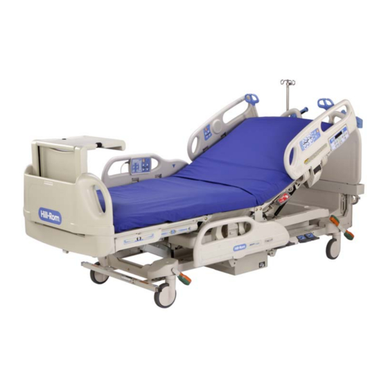
- Page 1 USER MANUAL VersaCare® From Hill-Rom Product No. P3200 and P3201 (K model and newer) 161956 REV 2...
- Page 3 For countries not listed on the back cover, contact your distributor. NOTE: The back cover is a comprehensive list of Technical Support contact information for Hill-Rom. The product discussed in this manual may not be available in all of the countries listed. VersaCare® Bed User Manual (161956 REV 2)
- Page 4 VersaCare® Bed User Manual (161956 REV 2)
-
Page 5: Table Of Contents
Table of Contents Document Symbols........... . . 1 Intended Use . - Page 6 Standard Patient Controls ..........25 Auto Contour™...
- Page 7 Siderail Pads (P855E7 and P855E7H) ........49 Utility Shelf (P417A) .
- Page 8 Treatment/Therapy Surface Functions ........65 The Surface Does Not Inflate or Does Not Inflate Correctly ....65 Turn Assist Does Not Work.
-
Page 9: Document Symbols
Document Symbols This manual contains different typefaces and symbols to make the content easier to read and understand: • Standard text—used for regular data. • Boldface text—emphasizes a word or phrase. • NOTE:—sets apart special data or important instruction clarification. •... -
Page 10: Intended Use
This manual supplies information necessary for normal operation of the VersaCare® Bed from Hill-Rom. Before you operate the VersaCare® Bed, make sure you read and understand in detail the contents of this manual. It is important that you read and strictly obey the aspects of safety contained in this manual. -
Page 11: Features
Features Item Description Item Description Patient Siderail Control Panel CPR/Emergency Trendelenburg Release Mechanism Speaker Caregiver Foot Controls Line-of-Site® Trendelenburg Angle Line Manager (standard on some config- urations) Indicator Transport/Push Handle (shown with Night Light optional integrated IV holder) Control Pod (optional) IntelliDrive®... -
Page 12: Standard Features
Standard Features Emergency CPR When activated, the CPR release decouples the head section actuator so that the head section may lower to the horizontal position. This function is gas-assisted to cushion the movement and can be used when power is not available. If a treatment/therapy surface is installed and the bed has AC power, the surface will go into Max-Inflate to support a CPR board. -
Page 13: Caregiver Siderail Controls
To Activate 1. Make sure the bed is plugged into AC power or the battery is enabled. NOTE: To enable the battery, press any of the caregiver controls except the Lockout control. 2. Pull the CPR control handle with one hand. 3. -
Page 14: Lockout
Lockout The Lockout control on the caregiver siderail control panel disables the bed articulating functions. To Activate Simultaneously press the Lockout control and either direction control of the applicable function. Both patient and caregiver controls are locked out. A tone will sound and the applicable indicator will come on to let you know the lockout is activated. -
Page 15: Head Up/Down
Obstacle Detect™ System The VersaCare® Bed is equipped with the Obstacle Detect™ System that runs along the three open sides of the base frame. This system senses objects that are between the upper frame and the base frame. If the system senses an object, the Bed Not Down indicator on both siderails will flash, and you will not be able to lower the sleep deck. -
Page 16: Trendelenburg And Reverse Trendelenburg
Trendelenburg and Reverse Trendelenburg The VersaCare® Bed is capable of 15° Trendelenburg and 10° Reverse Trendelenburg. The Trendelenburg and Reverse Trendelenburg controls can be activated at any bed height. The Trendelenburg and Reverse Trendelenburg Line-of-Site® Angle Indicators are located in the intermediate siderails. -
Page 17: Bed Flat
Vascular Position The vascular position allows the caregiver to place the patient’s legs above the level of the patient’s sternum. To Activate 1. Lower the head section to the desired position. 2. Raise the knee section to the desired position. 3. -
Page 18: Foot Section Controls
To Activate 1. Set the brake. 2. Press the Chair control. The patient deck transitions to the chair position. If additional chair inclination is required, use the reverse Trendelenburg control to provide an additional 10° of forward chair movement. Foot Section Controls WARNING: The retractable foot section provides multiple patient benefits. -
Page 19: Safety And Information Indicators
Safety and Information Indicators NOTE: There must be power to the bed, either AC or battery, for the indicators to operate. Safety and information indicators give the caregiver visual and audio indications about Brake Status, AC Power, and Service Required. Disconnected from AC Power If the bed is disconnected from AC power, the plug indicator flashes. -
Page 20: Point-Of-Care® Brake And Steer Control
If the battery has been completely discharged, it may take up to 24 hours to charge to operational status. To make sure the battery is always charged, plug the bed into an applicable power source whenever possible. To Engage the Battery Back-Up Operation Press any of these controls except the Lockout control: NOTE: The battery stays engaged for one minute after the last control is pressed. -
Page 21: Head And Intermediate Siderails
Siderails are intended to be a reminder to the patient of the bed's edges, not a patient- restraining device. When appropriate, Hill-Rom recommends that medical personnel determine the proper methods necessary to make sure a patient remains safely in bed. - Page 22 The head-end siderails contain the Line-of-Site® Head Angle Indicators. The intermediate siderails contain the Line-of-Site® Trendelenburg/Reverse Trendelenburg Angle Indicators. NOTE: Some bed models with the caregiver pod do not have the Line-of-Site® Head Angle Indicators. For those beds, the head angle continuously shows on the digital display. To Raise a Siderail 1.
-
Page 23: Sleep Surfaces
NOTE: Hill-Rom recommends the use of Hill-Rom® surfaces that have been designed and tested specifically for the VersaCare® Bed. Customers electing to purchase replacement surfaces from other manufacturers should confirm that the replacement surface, when used in conjunction with the VersaCare®... -
Page 24: X-Ray Cassette Sleeve
The nano Ag+® Technology with SmartSilver® Ions is available on all VersaCare® Bed surfaces. This technology does not affect the operation of the surface. X-Ray Cassette Sleeve An x-ray cassette sleeve is available on some surfaces and permits a 17" x 14" x-ray cassette to be inserted from either side of the coverlet. - Page 25 NOTE: We recommend that you do not use accessories such as plastic underpads with the P500. Such products can prevent the flow of moisture from the patient’s skin to the microclimate management coverlet. The treatment/therapy surfaces consist of three air zones and one foam zone. The three air zones control interface pressure in the head and torso, seat, and heel areas of the patient to help prevent pressure ulcers.
- Page 26 To Activate 1. Press the Enable control. 2. Press and release the Max-Inflate control. An indicator will illuminate when the mode is active. To Deactivate 1. Press the Enable control. 2. Press the Normal control. Heel Relief Heel Relief is achieved by lengthening or shortening the bed foot section to align the patient's heels in the heel relief zone.
- Page 27 NOTE: If the siderails are not in the correct position or the head section is not below 25°, an indicator will flash and an alarm will sound. Siderail Not 3. Press the Enable control. 4. Press and release the Left/Right Turn Assist control. The indicator will illuminate.
-
Page 28: Sleep Surface Removal And Installation
Off Mode WARNING: Do not use the Off Mode when a patient is on the bed. Using the Off Mode with a patient on the bed could result in patient injury. The Off Mode disables the air system to allow for cleaning or maintenance. The Off Mode should not be used with a patient on the bed. - Page 29 7. For a Tempur-Pedic®Mattress with clip attachments, disconnect the clips from the retainers. Retainer Clip 8. For other mattresses, do as follows: a. Carefully remove one side of the mattress retaining strap from the retainer. b. Remove the opposite side of the mattress retaining strap from the retainer. 9.
-
Page 30: Surface Overlays
b. Install the opposite side of the mattress retaining strap into the retainer. • Tempur-Pedic® Mattress with clip attachments—align each clip with its retainer, and press down on the mattress to attach the clip to the retainer. Retainer Clip • Treatment/therapy surface—make all hose connections to the bed frame. -
Page 31: Patient Hip Position Indicator
Patient Hip Position Indicator The patient hip position indicator is located on the inside of the intermediate siderails. The indicator is used to help make sure the patient is in the most ergonomic position. Headboard The headboard is located at the head end of the bed. It attaches to the head end of the frame, and does not move up and down with the sleep deck. -
Page 32: Patient Restraints
Restraints must be attached to the articulating sections of the bed at the correct attachment points. Failure to do so may result in patient injury. The VersaCare® Bed facilitates the use of vest, wrist, and waist restraints. Hill-Rom makes no recommendation regarding the use of physical restraints. Users should refer to legal restrictions and appropriate facility protocols before physical restraints are used. -
Page 33: Equipment Sockets
Equipment Sockets There are four equipment sockets for the attachment of accessories. They are at each corner of the bed. The equipment sockets can be used to mount IV poles, ISS poles, and oxygen tank holders. NOTE: The head-end equipment sockets do not move up and down with the bed frame. -
Page 34: Additional Features
Additional Features NOTE: The features shown below are standard on some bed configurations and optional on others. Boost® Position System WARNING: Do not use the Boost® function if there are concerns of spinal instability. To do so could cause patient injury. The Boost®... -
Page 35: 30° Head Angle Alarm
30° Head Angle Alarm The Head Angle Alarm control is on the caregiver pod next to the display. When set, if the head section goes below 30°, these will occur: • The display will flash five times. • An audible alarm will come on. •... -
Page 36: Cord Wrap Clips With Iv Pole Storage
WARNING: Failure to remove lines from the Line Manager before you transfer the patient could cause patient injury or equipment damage. A Line Manager is on each side of the head end of the bed. The Line Manager helps to keep lines (such as IV fusion lines, suction lines, oxygen lines, etc.) together and away from the articulating frame. -
Page 37: Integrated Iv Transport Handle
To Remove from the Stowed Position 1. Pull the shelf out from the footboard, and up to the applicable height. Make sure there is sufficient space for the patient’s foot movement. 2. Turn the shelf horizontally so it is above the foot section of the sleep surface. -
Page 38: Optional Features
Optional Features Push Handles The push handles are available as an option. Remove from the Stowed Position Pull the push handles upward until they lock in position. Stow 1. Lift up on the push handles to unlock them. 2. Move the push handles in toward the center of bed to the stowed position. -
Page 39: Patient Pendant
To Activate Press a Nurse Call control. When the nurses station acknowledges the call, these will occur: • The Nurse Call indicator on the caregiver control panel will illuminate. • The Voice indicator on the patient controls will illuminate. The nurses station is ready for you to speak. -
Page 40: Patient Controls
Patient Controls The Head Up/Down and Knee Up/Down controls are standard on the patient pendant. These functions do not require the bed to be connected to a SideCom® Communication System. However, the optional controls that follow do require the bed to be connected to a SideCom®... -
Page 41: Scale System
Scale System The scale system for the VersaCare® Bed has an accuracy of 1% and an operating range of 0 lb to 500 lb (0 kg to 227 kg). The scale display and controls are located on the flip-up control pod on the head-end siderails. The scale is very sensitive. -
Page 42: Bed Setup
Bed Setup For best results, do the following before placing the patient on the bed: 1. Make sure the bed is plugged into electrical power. 2. Put all linens, blankets, pillows, equipment, and other items on the bed. A list of these items posted near the bed may be helpful for future reference. -
Page 43: Bed Exit Alarm System
Bed Exit Alarm System WARNING: The Bed Exit Alarm System is not intended as a substitute for good nursing practices. The Bed Exit Alarm System must be used in conjunction with a sound risk assessment and protocol. The Bed Exit Alarm System (Bed Exit) control is located on the flip-up control pod on the outside of the head-end siderails. - Page 44 To Silence the Bed Exit Alarm System without Deactivating the System When a Bed Exit mode is armed, you can silence the alarm system. During this Silence mode, the system stops monitoring the patient movement; therefore, the system does not turn on the audible alarm or send a nurse call alarm.
-
Page 45: Intellidrive® Transport System
1. Activate one of Bed Exit modes. It is recommended to use another caregiver instead of a patient to activate the Bed Exit mode. 2. Activate the alarm by having the caregiver exit the bed. 3. Press and hold the Volume control. 4. - Page 46 CAUTION: The powered transport system is intended for indoor use only. Outdoor use may cause temporary or permanent damage to the powered drive mechanism and/or drive belt. To Prepare the Bed for Transport 1. Raise all four siderails to the up and locked position.
-
Page 47: Auxiliary Ac Receptacle Option (120 V Version Only)
WARNING: In case of battery or motor power loss, toggle the electronic brake switch to OFF. This permits manual movement of the bed with a deployed, unpowered system. An electronic brake switch is located on the right side of the drive housing. If during a transport, the battery fails or there is a loss of motor power, toggle the electronic brake switch to OFF. -
Page 48: Navicare® System
NaviCare® System The NaviCare® System is an enterprise system that connects and monitors Hill-Rom® beds and surfaces. The system sends bed and surface data to network applications for caregivers to view and receive alerts. For complete operational instructions for the NaviCare®... -
Page 49: Wireless Interface Unit
Wireless Interface Unit Amber The wireless interface unit (WIU) permits the bed Green and surface data to be sent through the NaviCare® System without a communication cable. WARNING: A communication cable must be used for beds that have Nurse Call. Failure to do so could cause patient injury. -
Page 50: Deactivate The Safeview® Alerts
The SafeView® Alerts show a steady green when Bed Exit is active and all of the conditions below are met. If one or more of these conditions are not met, the Alerts flash yellow: • The bed is in the low position. •... -
Page 51: Configure The Siderails For The Safe Bed Condition
NOTE: The Alerts will stay off until you activate Bed Exit again or you disconnect the bed from AC power and then connect the bed to AC power. NOTE: If the Alerts are deactivated on a bed with the optional head angle alarm that is active, the Alerts will not flash yellow if the head section goes below the specified angle. -
Page 52: Accessories
Accessories Part Number Description P2217 IV Pole P158 Infusion Support System Transfer Pole P158A01 Infusion Support System Transfer Pole Assembly P276 Vertical Oxygen Tank Holder, E-size P844G48 Patient Helper Adapter Bracket P844G01/02 Patient Helper Adapter Bracket P3212A Patient Helper Sleeve P3211B Fracture Frame Adapter Bracket P2222A... -
Page 53: Infusion Support System (P158 And P158A01)
CAUTION: When lowering the upper section of an IV pole, always grasp and hold the upper section of the pole before pulling the release knob. Failure to do so may cause equipment damage. NOTE: Make sure when you mount infusion pumps on an IV pole that they do not interfere with the head section articulation. -
Page 54: Oxygen Tank Holder, E-Size (P276)
The head end of the system has attaching points for two mobile ISS. Each ISS can support one infusion pump plus two liters of intravenous solution. Before installing the ISS pole (P158), it is necessary to install the P163 adapter bracket. The P158A01 has the P163 adapter installed. -
Page 55: Patient Helper Adapter Bracket (P844G48)
Patient Helper Adapter Bracket (P844G48) The patient helper adapter bracket (P844G48) is for use with the patient helper available from Orthopedic Systems, Inc. The P844G48 has the support tube built into the frame assembly. Refer to the equipment manufacturer’s instructions for installation procedures. -
Page 56: Patient Helper Adapter Bracket (P844G01/02) And (P3212A)
Patient Helper Adapter Bracket (P844G01/02) and (P3212A) The patient helper adapter bracket P844G01 (P844G01) is for use with patient helper sleeves from traction equipment manufacturers. P3212A The patient helper sleeve (P3212A) must be installed before the adapter bracket is installed on the bed. Refer to the equipment manufacturer’s instructions for installation procedures. -
Page 57: Siderail Pads (P855E7 And P855E7H)
WARNING: The head-end equipment sockets do not move up and down with the sleep deck. Use appropriate precautions with gravity-sensitive devices such as ventricular drains or lumbar drains before, during, and after operating bed functions. Make sure flow rates on all gravity-fed IVs are correct after bed height adjustment. Failure to correctly manage patient equipment could result in patient injury. -
Page 58: Utility Shelf (P417A)
Utility Shelf (P417A) WARNING: Do not exceed the 45 lb (20.4 kg) utility shelf weight capacity. If the utility shelf is overloaded, personal injury or equipment damage could occur. The utility shelf can be installed at the foot end of the bed. The utility shelf measures 15"... -
Page 59: Continuous Passive Machine Support (P004943)
Continuous Passive Machine Support (P004943) WARNING: Do not exceed the 50 lb (22.7 kg) safe working load of the CPM support. If the support is overloaded, personal injury or equipment damage could occur. The continuous passive machine (CPM) support can be installed at the foot end of the bed. -
Page 60: Siderail-Mounted Wipe Dispenser (P3204A01)
2. Pull the release pins. 3. Push down on the extender until it stops, and then push in the release pins. 4. Pull up on the extender to make sure the pins keep the extender in position. Siderail-Mounted Wipe Dispenser (P3204A01) For installation, refer to the instructions included with the dispenser. -
Page 61: Safety Tips
Safety Tips Bed Positions WARNING: It is recommended that the bed be in the low position when the patient is unattended. This may reduce the severity of any resultant injuries from patient falls. WARNING: When a patient’s condition (such as disorientation due to medication or clinical condition) could lead to patient entrapment, the sleep deck should be left in the flat and lowest position while unattended (except when required otherwise by medical staff for special or particular circumstances). -
Page 62: Siderails/Restraints/Patient Monitoring
Siderails are intended to be a reminder to the patient of the bed's edges, not a patient- restraining device. When appropriate, Hill-Rom recommends that medical personnel determine the proper methods necessary to make sure a patient remains safely in bed. -
Page 63: Electricity
For restraining devices, consult the restraint manufacturer’s instructions for use to verify the correct application of each restraining device. Electricity Policies and procedures must be established to train and educate your staff on the risks associated with electric equipment. It is never prudent or necessary for personnel to place any part of their body under or between moving parts of the bed. -
Page 64: Parts And Accessories
WARNING: No battery back-up. For non-life support medical equipment only. Auxiliary receptacle ground separated from bed ground. Parts and Accessories Use only Hill-Rom parts and accessories. Do not modify the bed system without authorization from Hill-Rom. Operating Bed/Surface Precautions WARNING: Do not operate the bed in the presence of flammable gas or vapors. -
Page 65: Transport Position And Stability
The VersaCare® Bed is intended to be used to transport patients with the foot end of the system forward. Prior to transport, properly stow the power cord to prevent tripping. Take care to prevent damage to the AC power cord. An electrical shock hazard exists. Use only the headboard, transport handles (if installed) or the footboard to move the bed. -
Page 66: Sleep Surface/Mattress
NOTE: Hill-Rom recommends the use of Hill-Rom surfaces that have been designed and tested specifically for the VersaCare® Bed. Customers electing to purchase replacement surfaces from other manufacturers should confirm that the replacement surface, when used in conjunction with the VersaCare®... -
Page 67: Bed Articulations
Bed Articulations WARNING: Observe lines closely during articulations. Always use good line management techniques, particularly as the head section rises. Failure to do so could cause patient injury or equipment damage. Do not operate bed controls until all persons and equipment are clear of mechanisms. To stop a function, release the control, and/or activate the opposite function, and/or immediately unplug the AC power cord. -
Page 68: Clean And Disinfect
Clean and disinfect surfaces with nano Ag+® Technology as you would other surfaces. This product is not intended to protect users or others against bacteria, viruses, germs, or other disease organisms. Always disinfect Hill-Rom surfaces thoroughly after each use according to facility protocol. -
Page 69: Disinfect
3. Use these to clean the bed: • A soft cloth soaked with warm water and a facility-approved general cleaning soap/detergent solution. Make sure the cloth is not so wet as to cause the cleaning solution to pool or flood on the mattress or other bed components. •... - Page 70 3. Wipe down the surface with chlorine bleach (50 ppm to 150 ppm) or mild detergent and warm water followed by an approved intermediate level disinfectant, such as CSI disinfectant cleaner. NOTE: 2.5 oz of bleach per 10 gal of water is approximately 100 ppm of available chlorine. 4.
-
Page 71: Preventive Maintenance
Preventive Maintenance WARNING: Only facility-authorized personnel should service the VersaCare® Bed. Servicing performed by unauthorized personnel could result in personal injury or equipment damage. The VersaCare® Bed requires an effective maintenance program. We recommend that you perform annual preventive maintenance (PM) and testing for The Joint Commission (formerly JCAHO). -
Page 72: Troubleshooting
Troubleshooting WARNING: Only facility-authorized persons should service the VersaCare® Bed. Service by unauthorized persons could cause injury or equipment damage. If the troubleshooting information shown below does not fix the problem, contact your facility-authorized maintenance person. Bed Functions The Bed Controls Do Not Work Make sure of these: •... -
Page 73: The Display On The Control Pod Flashes When A Weight Is Taken
The Display on the Control Pod Flashes when a Weight Is Taken The maximum weight the scale will show has been exceeded. The Head Section Angle Appears to be different than the Head Angle Display Shows Contact your facility-authorized maintenance person. The Bed Exit Alarm Does Not Arm and All Three Mode Indicators are Flashing Remove the patient, and zero the Bed Exit system. -
Page 74: Turn Assist Does Not Work
Turn Assist Does Not Work • Make sure the bed is plugged into AC power. • Make sure the siderails that the patient is turning toward are in the up and locked position. • Make sure the head section is below 25°. •... -
Page 75: Product Symbols
Product Symbols These symbols may or may not be used on your model of the VersaCare® Bed: Symbol Description Type B applied part according to IEC 60601-1 (UL 60601-1). According to IEC 60529, rating for protection against fluid ingress. IPX4 CAUTION: Consult accompanying documents. - Page 76 Symbol Description Safe Working Load—indicates the safe working load of the bed. Electric shock hazard. Alternating current. Identifying mains fuse. Manufacturer or distributor complies with the Waste Electric and Electronic Equipment Directive 2002/96/EC. Patient Hip Position Locator—shows the optimal patient placement on the bed.
- Page 77 Symbol Description Shows there is a pinch point under the foot section. Shows that you should not step on this area of the bed. Shows the head-end IV poles remain stationary in height when the sleep surface is raised or lowered. Fracture frame articulation Warning—the sleep deck moves indepen- dently of bed frame.
- Page 78 Symbol Description CPR/Emergency Trendelenburg Control—activates the CPR function and the Emergency Trendelenburg position. Bed Up/Down control—raises and lowers the bed. Head Up/Down control—raises and lowers the head section. Knee Up/Down control—raises and lowers the knee section. Foot Shorter and Foot Longer controls—shortens and lengthens the foot section.
- Page 79 Symbol Description Lockout control—locks out and unlocks bed articulation functions. For all motor lockout, you must press the lockout control and each articulation control. Trendelenburg control—activates the Trendelenburg function. Reverse Trendelenburg control—activates the Reverse Trendelen- burg function. Chair control—activates the Chair function. Boost®...
- Page 80 Symbol Description Plug indicator—flashes when the bed is disconnected from AC power. Battery indicator—is on when the battery is active; flashes when the battery needs charged; is off when the battery is inactive or is dis- charged below the level necessary to operate the motors. Nurse Call control on the patient controls—sends a Nurse Call to the nurses station.
- Page 81 Symbol Description Television control—turns the television on and off. (Patient control pendant only) Closed Captioning control—turns the closed captioning option of a television on or off. (Patient control pendant only) Volume control—raises or lowers the volume of the television or radio.
- Page 82 Symbol Description Zero control—zeroes the scale. Scale Weigh control—operates the scale feature on the bed. If the scale feature is enabled, the patient weight will show on the display. 30° Head Angle Alarm control—sets the alarm. When the head sec- tion of the bed goes below 30°, an alarm comes on and the alarm indicator flashes.
- Page 83 Symbol Description Normal Mode—places the treatment/therapy surface into normal mode. (Only available on beds with a treatment/therapy surface) Max-Inflate mode—inflates the treatment/therapy surface into Max- Inflate. (Only available on beds with a treatment/therapy surface) Patient Position Mode—alarms when a patient moves towards either siderail or moves away from the head section, such as sits up in bed.
- Page 84 Symbol Description Transport sequence (beds with the IntelliDrive® Transport System) Transport the patient with the lift arms parallel to the ground or lower. Transport the patient with the foot end of the bed forward. Use only the footboard or push handles to move the bed. Shows the OFF position for the IntelliDrive®...
-
Page 85: Specifications
Specifications Product Identification Product Number Description P3200 and P3201 VersaCare® Bed Dimensions Feature Dimension Total Length: Foot Section Lengthened 94.5" (240.0 cm) beds without the integrated transport shelf in the footboard 97" (246 cm) beds with the integrated transport shelf in the footboard Foot Section Shortened 82.5"... - Page 86 Feature Dimension Bed Height Range, Lowest Position 13" (33.0 cm) (from the floor to the center of the deck) 17" (43.2 cm) (from the floor to the edge of the deck) NOTE: The optional IntelliDrive® Transport System or 6" casters add height to these dimensions: IntelliDrive adds 4"...
- Page 87 AC Power Requirements Nominal Power Distribution Nominal Power Distribution Maximum Equipment Voltage (Volts) Frequency (Hertz) Current (Amps) 120 (P3200) 100/110/115/120/127 (P3201) 50/60 220/230/240 (P3201) 50/60 a. North American power supply configuration. Auxiliary Outlet Power Specifications (120V Beds Only) Condition Range Auxiliary Receptacle 120V AC, 60 Hz, 8 A outlet, electrically isolated from the bed’s mains power.
- Page 88 Classification and Standards The VersaCare® Bed is designed and manufactured according to the following equipment classifications and standards: Technical and Quality Assurance Standards UL 60601-1 CSA® C22.2 No. 601.1 IEC/EN 60601-2-38 IEC/EN 60601-1 IEC 60601-1-2 IEC 60601-1-4 EN 13485 Equipment Classification per IEC 60601-1 Class I equipment, internally powered equip- ment Degree of Protection Against Electric Shock...
- Page 89 Medical equipment needs special precautions in regard to electromagnetic compatibility (EMC) and needs to be installed and put into service according to the EMC information supplied in the tables that follow. Guidance and Manufacturer's Declaration—Electromagnetic Emissions The P3200/P3201 is intended for use in the electromagnetic environment specified below. The customer or the user of the model P3200/P3201 should make sure it is used in such an environment.
- Page 90 Guidance and Manufacturer's Declaration - Electromagnetic Immunity The P3200/P3201 is intended for use in the electromagnetic environment specified below. The customer or the user of the P3200/P3201 should make sure it is used in such an environment. Electromagnetic IEC 60601 Immunity Test Compliance Level Environment—...
- Page 91 Electromagnetic Immunity Guidance Guidance and Manufacturer's Declaration - Electromagnetic Immunity The P3200/P3201 is intended for use in the electromagnetic environment specified below. The customer or the user of the P3200/P3201 should make sure it is used in such an environment. Immunity IEC 60601 Compliance...
- Page 92 Changes and/or modifications not expressly approved by Hill-Rom Co., Inc. could void the user's authority to operate the equipment. The WIU must be installed and used in accordance with the Hill-Rom user and installation instructions. Hill-Rom is not responsible for any radio or television interference caused by...
- Page 93 Any other installation or use will violate FCC Part 15 regulations. Modifications not expressly approved by Hill-Rom could void your authority to operate the equipment. The Hill-Rom WIU device must not be co-located or operated in conjunction with any other antenna or transmitter. Canada—Industry Canada (IC) •...
- Page 94 L'utilisation de ce dispositif est autorisée seulement aux conditions suivantes: (1) il ne doit pas produire de brouillage et (2) l'utilisateur du dispositif doit étre prêt à accepter tout brouillage radioélectrique reçu, même si ce brouillage est susceptible de compromettre le fonctionnement du dispositif.
- Page 96 Fax: +1 (0)812 934 7191 www.hill-rom.com international@hill-rom.com Australia Belgique/België Canada Hill-Rom Australia Pty. Ltd. Hill-Rom Medical Services BV Hill-Rom Canada Tel: +61 (0)2 8814 3000 Tel: +31 (0)347 / 32 35 32 Tel: 800-267-2337 Fax: +61 (0)2 8814 3030...
Need help?
Do you have a question about the VersaCare Bed and is the answer not in the manual?
Questions and answers
where is the air blower button on the versacare p500