Sign In
Upload
Manuals
Brands
Hill-Rom Manuals
Medical Equipment
VersaCare P3201
Hill-Rom VersaCare P3201 Manuals
Manuals and User Guides for Hill-Rom VersaCare P3201. We have
2
Hill-Rom VersaCare P3201 manuals available for free PDF download: Service Manual, User Manual
Hill-Rom VersaCare P3201 Service Manual (379 pages)
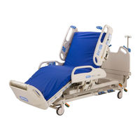
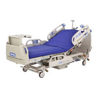
Bed
Brand:
Hill-Rom
| Category:
Medical Equipment
| Size: 9 MB
Table of Contents
Table of Contents
7
Chapter 1: Introduction
19
Purpose
19
Audience
19
Organization
19
Chapter 2: Troubleshooting Procedures
19
Chapter 3: Theory of Operation
19
Chapter 4: Removal, Replacement, and Adjustment Procedures
20
Chapter 5: Parts List
20
Chapter 6: General Procedures
20
Chapter 7: Accessories
20
Document Symbol Definition
21
Overview
22
Specifications
23
Electrical Description
25
Regulations, Standards, and Codes
25
Model Identification
29
Safety Tips
30
Warning and Caution Labels
33
Chapter 2: Troubleshooting Procedures
35
Getting Started
35
Initial Actions
36
Rapid Problem/Solution Identification Tables
37
Function Checks
40
Treatment Surface Function Check
44
Final Actions
46
Electronics (Sheet 1 of 2)
47
Electronics (Sheet 2 of 2)
48
Logic P.C. Board Diagnostic LED Codes
49
Bootloader, Supervisory Relay Error, EEPROM Failure, and All Lockout LED Error
50
Head, Knee, Hilow Lockout LED Error and CPR Switch Failure
51
Hilow Motor Unexpected Motion
52
Head, Knee, Leg, and Foot Motor Unexpected Motion
53
Motor Overcurrent
54
Hilow Motor Position Rate High
55
Hilow Motor Position Rate Low
56
Absolute Minimum Drive Current Failure
57
Network Heartbeat Failure System Level
58
Patient pendant Causing Logic P.C. Board Failure
59
Logic Circuit Failure
60
Nuisance Trip
61
Motors Do Not Operate
62
No AC Power
63
AC Power, no Motor Power
64
No DC Power
65
Power Supply Error Codes
66
Siderail Controls Not Working
67
Siderail Detection Switch Without Sidecom® Communication System
68
Siderail Detection Switch with Sidecom® Communication System
69
Air Surface (Sheet 1 of 2)
70
Air Surface (Sheet 2 of 2)
71
System Error, no Flash Code
72
Mattress Disconnected
73
Head Angle Sensor Error
74
Head FSR1 and FSR2
75
Accumulator Pressure
76
Missing 24 V DC Input
77
Not Reaching Head Zone Pressure
78
Not Reaching Seat Zone Pressure
79
Not Reaching Foot Zone Pressure
80
Not Reaching Right Turn Assist Pressure
81
Not Reaching Left Turn Assist Pressure
82
Scale Error 0
83
Scale Error 1
84
Scale Error 2
85
Scale Error 3
86
Scale Error 4 and 5 (European Scale Only)
87
Sidecom® Communication System
88
Patient Position Monitor System with Scale Display
89
Patient Position Monitor Without Scale Display
90
CRC Error
91
Patient pendant
92
Obstacle Detection
93
Bed will Not Drive (Intellidrive® Transport System)
94
Bed will Not Drive, Wheel Is down (Intellidrive® Transport System)
95
Wheel will Not Stow (Intellidrive® Transport System)
96
Battery Check (Intellidrive® Transport System)
97
Steer Switch Check (Intellidrive® Transport System)
98
PACM Board Power Check (Intellidrive® Transport System)
99
PACM Board Deployment Check (Intellidrive® Transport System)
100
PACM Board Drive Check (Intellidrive® Transport System)
101
Motor Check (Intellidrive® Transport System)
102
PACM to Junction Board Cable Check (Intellidrive® Transport System)
103
Handle Enable Switch Check (Intellidrive® Transport System)
104
Throttle Check (Intellidrive® Transport System)
105
Handle Gauge Check (Intellidrive® Transport System) (Sheet 1 of 3)
106
Handle Gauge Check (Intellidrive® Transport System) (Sheet 2 of 3)
107
Handle Gauge Check (Intellidrive® Transport System) (Sheet 3 of 3)
108
Controller Check-Intellidrive® Transport System
109
Visual Inspection-Intellidrive® Transport System
111
Junction Board Debugging-Intellidrive® Transport System
112
Base Frame Module
115
Chapter 3: Theory of Operation
115
Chapter 4: Removal, Replacement, and Adjustment Procedures
133
Tool and Supply Requirements
133
Introduction
115
Mechanical System
115
Hilow Lift Module
116
Upper Frame Module
116
User Interface Module
116
End Panel Module
117
Electrical System
118
Logic and Motor Control
118
Power Supply
119
User Interface
122
Patient pendant
123
Scale and Patient Position Monitor
124
Sidecom® Communication System
124
Intellidrive® Transport System
126
Pneumatic
130
Schematics
131
Mattress
135
Removal
135
Replacement
136
Caster
137
Removal
137
Replacement
139
CPR Cable
140
Removal
140
Replacement
142
Adjustment
142
Head Siderail
143
Removal
143
Replacement
147
Intermediate Siderail
148
Removal
148
Replacement
150
Head Siderail P.C. Board
151
Removal
151
Replacement
151
Speaker
153
Removal
153
Replacement
155
Patient Control P.C. Board
156
Removal
156
Replacement
158
Control Pod P.C. Board
159
Removal
159
Replacement
161
Night Light
162
Removal
162
Replacement
163
Foot Pedal Assembly
164
Removal
164
Replacement
165
Air Compressor
166
Removal
166
Replacement
168
Air Module
169
Removal
169
Replacement
171
Foot Hilow Motor
172
Removal
172
Replacement
176
Head Hilow Motor
178
Removal
178
Replacement
182
Head Section Motor
184
Removal
184
Replacement
188
Knee Section Motor
189
Removal
189
Replacement
192
Foot Motor
193
Removal
193
Replacement
196
Foot Extend Motor
197
Removal
197
Replacement
200
Load Beam
201
Removal
201
Replacement
203
Battery
204
Removal
204
Replacement
205
AC Power Fuses
206
Removal
206
Replacement
207
Transformer and Battery Fuse
208
Removal
208
Replacement
209
Power Cord
210
Replacement
212
Power Supply P.C. Board
213
Removal
213
Replacement
214
Sidecom® Communication System P.C. Board
215
Removal
215
Replacement
217
Sensor Strip
218
Removal
218
Replacement
220
Obstacle Detect
221
Replacement
224
Logic Control P.C. Board
225
Removal
225
Replacement
226
Motor Control P.C. Board
227
Removal
227
Replacement
228
Scale System P.C. Board
229
Removal
229
Replacement
230
Intellidrive® Transport System Interface P.C. Board
231
Removal
231
Replacement
232
Battery-Intellidrive® Transport System
233
Removal
233
Replacement
235
PACM Board-Intellidrive® Transport System
236
Removal
236
Replacement
238
Drive Motor-Intellidrive® Transport System
239
Removal
239
Replacement
242
Drive Belt-Intellidrive® Transport System
243
Removal
243
Replacement
247
Transport Handle-Intellidrive® Transport System
248
Removal
248
Replacement
251
Motor Controller-Intellidrive® Transport System
252
Removal
252
Replacement
254
Head Section Bladder Assembly
255
Removal
255
Replacement
257
Seat Section Bladder Assembly
258
Removal
258
Replacement
260
Foot Section Bladder Assembly
261
Removal
261
Replacement
263
Turn Assist Bladder Assembly
264
Removal
264
Replacement
266
Chapter 5: Parts List
267
Chapter 6: General Procedures
341
Cleaning
341
General Cleaning
341
Board
342
Cleaning Hard to Clean Spots
342
Component Handling
342
Disinfecting
342
Steam Cleaning
342
Lubrication Requirements
343
Preventive Maintenance
344
Preventive Maintenance Schedule
345
Preventive Maintenance Checklist
351
Scale Calibration
352
Accessories
355
Chapter 7: Accessories
355
Infusion Support System-P158
356
Installation
356
Removal
356
Installation
357
Oxygen Tank Holder-P276
357
Removal
357
Installation
358
Removal
358
Standard IV Pole-P2217
358
Installation
359
Patient Helper Adapter Bracket-P844E48
359
Removal
359
Fracture Frame Adapter Bracket-P3211A
360
Service Parts Ordering
267
Exchange Policy
269
In-Warranty Exchanges
269
Out-Of-Warranty Exchanges
269
Warranty
271
Recommended Spare Parts
273
Base Frame
276
Casters
280
Obstacle Detection
282
Foot Controls
284
Articulating Frame
286
Head Siderail
288
Intermediate Siderail
292
Siderail Center Arm Assembly
294
Power Supply (Sheet 1 of 2)
296
Power Supply (Sheet 2 of 2)
300
Foot Extension
302
Air Compressor
304
Air Module
306
Footboard
308
Headboard
309
Sensor Strips
310
Sleep Deck
312
Intellidrive® Transport System
314
Intellidrive® Transport System-Drive Box
316
Intellidrive® Transport System-Drive Belt
320
Treatment Surface (P3251EA)
322
Short Stay Surface (P3250EA)
326
Permanent IV Pole
328
Labels (Sheet 1 of 2)
330
Labels (Sheet 2 of 2)
334
CPR Cable
338
Installation
360
Removal
360
Permanent IV Pole-P2222A
361
Installation
361
Removal
362
Advertisement
Hill-Rom VersaCare P3201 User Manual (96 pages)
Brand:
Hill-Rom
| Category:
Medical Equipment
| Size: 4 MB
Table of Contents
Table of Contents
5
Document Symbols
9
Intended Use
10
Introduction
10
Features
11
Standard Features
12
Emergency CPR
12
Emergency Trendelenburg
12
Caregiver Siderail Controls
13
Enable
13
Lockout
14
Bed Up/Down
14
Head Up/Down
15
Knee Up/Down
15
Trendelenburg and Reverse Trendelenburg
16
Bed Flat
17
Chair Positioning
17
Foot Section Controls
18
Safety and Information Indicators
19
Battery Back-Up
19
Point-Of-Care® Brake and Steer Control
20
Head and Intermediate Siderails
21
Sleep Surfaces
23
Surfaces with Nano Ag+® Technology with Smartsilver® Ions
23
X-Ray Cassette Sleeve
24
Np100
24
Treatment/Therapy Surfaces-A.I.R. and P500
24
Sleep Surface Removal and Installation
28
Surface Overlays
30
Foot Controls
30
Patient Hip Position Indicator
31
Headboard
31
Footboard
31
Patient Restraints
32
Drainage Bag Holders
32
Equipment Sockets
33
Night Light
33
Standard Patient Controls
33
Auto Contour™ Feature
33
Additional Features
34
Boost® Position System
34
Head Angle Display
34
30° Head Angle Alarm
35
Line Manager
35
Cord Wrap Clips with IV Pole Storage
36
Integrated Transport Shelf
36
Integrated IV Transport Handle
37
Optional Features
38
Push Handles
38
Sidecom® Communication System
38
Nurse Call Control
38
Patient Pendant
39
Patient Controls
40
Scale System
41
Scale Display
41
Changing the Scale Units
41
Bed Setup
42
Zeroing the Scale
42
Weighing the Patient
42
Bed Exit Alarm System
43
Intellidrive® Transport System
45
Auxiliary AC Receptacle Option (120 V Version Only)
47
Navicare® System
48
Wireless Interface Unit
49
Safeview® Alerts
49
Deactivate the Safeview® Alerts
50
Configure the Siderails for the Safe Bed Condition
51
Accessories
52
Pole (P2217)
52
Infusion Support System (P158 and P158A01)
53
Oxygen Tank Holder, E-Size (P276)
54
Patient Helper Adapter Bracket (P844G48)
55
Fracture Frame Adapter Bracket (P3211B)
55
Patient Helper Adapter Bracket (P844G01/02) and (P3212A)
56
Permanent IV Pole (P2222A)
56
Siderail Pads (P855E7 and P855E7H)
57
Utility Shelf (P417A)
58
VIP Headboard and Footboard
58
Continuous Passive Machine Support (P004943)
59
Siderail Extension Assembly (P3214A)
59
Siderail-Mounted Wipe Dispenser (P3204A01)
60
Siderail-Mounted Personal Effects Holder (P3204A02)
60
Safety Tips
61
Bed Positions
61
Brakes
61
Siderails/Restraints/Patient Monitoring
62
Electricity
63
Parts and Accessories
64
Operating Bed/Surface Precautions
64
Transport
64
Transport Position and Stability
65
Sleep Surface/Mattress
66
Flammability
66
Bed Articulations
67
Bed Transportation Mode
67
Visitor Notification
67
Clean and Disinfect
68
Clean
68
Disinfect
69
Clean the Mattress and the AMT Coverlet
69
Preventive Maintenance
71
Troubleshooting
72
Bed Functions
72
The Bed Controls Do Not Work
72
The Bed Does Not Lower
72
The Foot Controls Do Not Work
72
The Display on the Control Pod Is off
72
The Display on the Control Pod Flashes When a Weight Is Taken
73
The Head Section Angle Appears to be Different than the Head Angle Display Shows
73
Are Flashing
73
A Siderail Does Not Latch
73
Treatment/Therapy Surface Functions
73
The Surface Does Not Inflate or Does Not Inflate Correctly
73
Turn Assist Does Not Work
74
All Four Surface Mode Indicators Are Flashing
74
Product Symbols
75
Specifications
85
Advertisement
Related Products
Hill-Rom VersaCare P3200
Hill-Rom P3930
Hill-Rom CarePorter P3000
Hill-Rom PrimeAire P3252EA
Hill-Rom Affinity P3700E
Hill-Rom P500
Hill-Rom P1840
Hill-Rom Volara PVL1
Hill-Rom P633D3
Hill-Rom P201604
Hill-Rom Categories
Medical Equipment
Lifting Systems
Sling
Mobility Aid
Indoor Furnishing
More Hill-Rom Manuals
Login
Sign In
OR
Sign in with Facebook
Sign in with Google
Upload manual
Upload from disk
Upload from URL