
Related Manuals for Hill-Rom CareAssist P1170


Summary of Contents for Hill-Rom CareAssist P1170
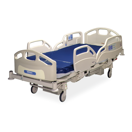
- Page 1 SERVICE MANUAL CareAssist™ From Hill-Rom Product No. P1170 For Parts or Technical Assistance man330 USA (800) 445-3720 Canada (800) 267-2337 International: Contact your distributor.
- Page 3 CareAssist™ Bed Service Manual Revisions Revision Letter Pages Affected Date Original Issue December, 2003 man330 CareAssist™ Bed Service Manual (man330) Page i...
- Page 4 Vice grip® is a registered trademark of American Tool Companies, Inc. The information contained in this manual is subject to change without notice. Hill-Rom makes no commitment to update or keep current, the information contained in this manual. Page ii...
- Page 5 Revisions The only product warranty intended by Hill-Rom is the express, written warranty accompanying the bill of sale to the original purchaser. Hill-Rom makes no other warranty, express or implied, and in particular, makes no warranty of merchantability or fitness for a particular purpose.
- Page 6 Revisions NOTES: Page iv CareAssist™ Bed Service Manual (man330)
-
Page 7: Table Of Contents
Table of Contents Chapter 1: Introduction Purpose ............1 - 1 Audience . - Page 8 Standard Casters ..........1 - 11 Brake and Steer Control .
- Page 9 Hilow Malfunction ..........2 - 14 Knee Section Malfunction .
- Page 10 Detection of Bed Not in Low Position ....... 3 - 9 Automatic Contour .
- Page 11 Removal ........... . . 4 - 24 Replacement .
- Page 12 Replacement ..........4 - 52 Patient Pendant Mount .
- Page 13 Component Handling ..........6 - 2 P.C.
- Page 14 NOTES: Page xii CareAssist™ Bed Service Manual (man330)
-
Page 15: Chapter 1: Introduction
Chapter 1 Introduction Purpose This manual provides requirements for the CareAssist™ Bed normal operation and maintenance. It also includes parts lists (in chapter 5) for ordering replacement components. Audience This manual is intended for use by only facility-authorized personnel. Failure to observe this restriction can result in severe injury to people and serious damage to equipment. -
Page 16: Chapter 4: Removal, Replacement, And Adjustment Procedures
Organization Chapter 1: Introduction Chapter 4: Removal, Replacement, and Adjustment Procedures Chapter 4 contains the detailed maintenance procedures determined necessary in chapter 2. Chapter 5: Parts List This chapter contains the warranty, part-ordering procedure, and illustrated parts lists. Chapter 6: General Procedures Cleaning, preventive maintenance, and other general procedures are described in this chapter. -
Page 17: Document Symbol Definition
Document Symbol Definition Chapter 1: Introduction Document Symbol Definition This manual contains different typefaces and icons designed to improve readability and increase understanding of its content. Note the following examples: • Standard text—used for regular information. • Boldface text—emphasizes a word or phrase. •... -
Page 18: Standard Features
Standard Features Chapter 1: Introduction Standard Features Emergency CPR Controls The emergency CPR control handles are located at the head end of the bed, under each corner of the sleep deck To Activate • Pull the CPR control handle (A) with one hand (see figure 1-5 on page 1-4). -
Page 19: Lockout Control
Standard Features Chapter 1: Introduction To Activate • Press the Enable control. The Enable control is active for approximately 60 seconds. • During the 60-second period, you may activate the Trendelenburg and Reverse Trendelenburg controls without pressing the Enable control again. The 60-second period will start over when another Trendelenburg control is pressed. -
Page 20: Bed Up/Down Control
Standard Features Chapter 1: Introduction To Deactivate Press and hold the Lockout control, and then press the locked out control. The Lockout control disables only articulation controls, not Nurse Call. No movement of the unit is allowed, except for emergency CPR, Trendelenburg, and Reverse Trendelenburg. -
Page 21: Automatic Contour Feature
Standard Features Chapter 1: Introduction Automatic Contour Feature The automatic contour feature is activated by using the Head Up control. The automatic contour feature raises the head section and the knee section simultaneously. The automatic contour feature is m330_093 active only when both the head section and knee section are not locked out. -
Page 22: Trendelenburg And Reverse Trendelenburg Controls
Standard Features Chapter 1: Introduction Trendelenburg and Reverse Trendelenburg Controls The powered Trendelenburg and Reverse Trendelenburg controls can be activated at any bed height and are located on the head siderails. The Trendelenburg and Reverse Trendelenburg Trendelenburg Line-of-Site® Angle Indicators are located in the foot end siderails. -
Page 23: Bed Flat Control
Standard Features Chapter 1: Introduction Bed Flat Control The Bed Flat control, located on the head siderails, only returns the sleep deck to a flat position, it does not change the angle of the bed. m330_038 To Activate Press and hold the Bed Flat control. When all sections are flat, the system stops. -
Page 24: Fullchair® Patient Positioning Mechanism
Standard Features Chapter 1: Introduction FullChair® Patient Positioning Mechanism To Activate • Set the brake. • Press the Dining Chair™ Position control. The patient deck transitions to the chair position. • When the bed has finished m330_094 traveling, press the Enable control. •... -
Page 25: Battery Control
Standard Features Chapter 1: Introduction Battery Control The battery function is available only when the bed is not connected to AC power and is located on the head siderails. To Activate • Unplug the bed from its power source. m330_013 •... -
Page 26: Brake And Steer Control
Standard Features Chapter 1: Introduction Brake and Steer Control WARNING: Unless transporting the patient, always set the brakes when the unit is occupied. Reconfirm that the brakes are set before any patient transfer. Failure to do so may result in personal injury or equipment damage. The brake and steer control is located under the foot section. -
Page 27: Head And Foot Siderails
Standard Features Chapter 1: Introduction Head and Foot Siderails The head siderail contains the Line-of-Site® Head Angle Indicators and the foot siderail contains the Trendelenburg/Reverse Trendelenburg Line-of-Site® Angle Indicators. m330_021 m330_041 To Raise a Siderail • Pull the siderail up until it latches into the locked position. -
Page 28: Headboard
Standard Features Chapter 1: Introduction Headboard The headboard is located at the head end of the bed. It attaches to the head end of the frame. It does not articulate with the sleep deck. To Remove m330_049 Grasp the headboard, and lift it straight up. To Install •... -
Page 29: Equipment Sockets
Standard Features Chapter 1: Introduction Equipment Sockets There are four equipment sockets, one at each corner, for the attachment of accessories. The equipment sockets can be used to mount IV poles, ISS poles, traction equipment, and oxygen tank holders. NOTE: m330_033 The IV poles and ISS poles require an adapter to be installed prior to use. -
Page 30: Standard Patient Controls
Standard Features Chapter 1: Introduction Standard Patient Controls The patient controls are located on the patient pendant, which can be installed in any siderail. The standard patient controls include: Head Up/Down and Knee Up/Down. They operate in the same manner as the caregiver siderail controls. -
Page 31: Bed Exit Control (Optional)
Standard Features Chapter 1: Introduction • Speak into the speaker/microphone located on the inside of the head siderails. NOTE: The Enable control does not need to be activated prior to pressing a Nurse Call control. The Nurse Call controls are always active. The Nurse Call controls cannot be locked out. -
Page 32: Patient Controls (Optional)
Standard Features Chapter 1: Introduction Patient Controls (Optional) The optional patient controls are located on the patient pendant. m330_028 Nurse Call Control (Optional) The Nurse Call control is located on the inside of the head siderails and on the patient pendant. The patient Nurse Call control functions in the same manner as the caregiver Nurse Call control (see “Nurse Call Control (Optional)”... -
Page 33: Volume Control (Optional)
Standard Features Chapter 1: Introduction Volume Control (Optional) The volume control allows the patient to adjust the volume of the television or radio in the room. m330_047 Channel Control (Optional) The channel control allows the patient to change channels on the television or stations on the radio in the room. -
Page 34: Physical Description
Physical Description Chapter 1: Introduction Physical Description For CareAssist™ Bed specification, see table 1-1 on page 1-20 through table 1-9 on page 1-23. Table 1-1. Dimensions Feature Dimension Total length 100" (254 cm) Maximum width (siderails stored) 40" (102 cm) Maximum width (siderails up) 40"... - Page 35 Physical Description Chapter 1: Introduction Table 1-3. Environmental Conditions for Transport and Storage Condition Range Temperature -40°F to 122°F (-40°C to 50°C) Relative humidity 95% non-condensing Pressure 50 kPa to 106 kPa Nurse Call Connection Requirements For information about the Nurse Call connection requirements, refer to the SideCom® Com- munication System Design and Application Manual (ds059).
- Page 36 Physical Description Chapter 1: Introduction Table 1-5. AC Power Requirements Condition Range Rated voltage 120 V~ Power/input 4.0 A Frequency 60 Hz Table 1-6. Fuse Specifications Condition Range Battery fuse 10 A, 32 V~, ATO Mains fuse 2 each 2.5 A, 250 V~, 5 x 20 mm, UL 198G Slo-Blo®...
- Page 37 Physical Description Chapter 1: Introduction Table 1-8. Electromagnetic Emissions Guidance Guidance and Manufacturer's Declaration—Electromagnetic Emissions The CareAssist™ Bed model P1170 is intended for use in the electromagnetic environment specified below. The customer or the user of the model P1170 should make sure it is used in such an environment. Emissions Test Compliance Electromagnetic Environment—Guidance...
- Page 38 Physical Description Chapter 1: Introduction Guidance and Manufacturer's Declaration—Electromagnetic Emissions The CareAssist™ Bed model P1170 is intended for use in the electromagnetic environment specified below. The customer or the user of the model P1170 should make sure it is used in such an environment. IEC 60601 Electromagnetic Immunity Test...
-
Page 39: Model Identification
Model Identification Chapter 1: Introduction Model Identification For CareAssist™ Bed model identification, see table 1-10 on page 1-25. Table 1-10. Model Identification Model Number Description P1170 CareAssist™ Bed CareAssist™ Bed Service Manual (man330) Page 1 - 25... -
Page 40: Safety Tips
Safety Tips Chapter 1: Introduction Safety Tips WARNING: Only facility-authorized personnel should service the CareAssist™ Bed. Servicing performed by unauthorized personnel could result in personal injury or equipment damage. WARNING: Adhere to appropriate infection control policies and procedures. Failure to do so could result in the spread of infection. WARNING: To prevent injury from sharp edges and rough surfaces, wear protective gloves. - Page 41 Safety Tips Chapter 1: Introduction CAUTION: Do not use silicone-based lubricants. Equipment damage could occur. CAUTION: To prevent component damage, make sure that your hands are clean, and only handle the P.C. board by its edges. CAUTION: When handling electronic components, wear an antistatic strap. Failure to do so could result in component damage.
-
Page 42: Warning And Caution Labels
Warning and Caution Labels Chapter 1: Introduction Warning and Caution Labels Figure 1-6. Warning and Caution Labels m330_098 m330_057 m330_055 m330_063 Safe Working Do Not Do Not No Oxygen Load Throw Away Stack Tents Footboard Position Indicator Grounding Point Position Page 1 - 28 CareAssist™... -
Page 43: Chapter 2: Troubleshooting Procedures
(replacing or adjusting a part, seating a connector, etc.), perform the Function Checks. To verify the repair, perform the Final Actions after the Function Checks. If troubleshooting procedures do not isolate the problem, call Hill-Rom Technical Support at (800) 445-3720 for assistance. CareAssist™ Bed Service Manual (man330) -
Page 44: Initial Actions
Initial Actions Chapter 2: Troubleshooting Procedures Initial Actions Use Initial Actions to gather information from operators concerning problems with the CareAssist™ Bed. Note the symptoms or other information concerning the problem that the operator describes. This information helps identify the probable cause. 1. - Page 45 Initial Actions Chapter 2: Troubleshooting Procedures Problem Solution Bed Connected to AC Power, Brakes Not Applied Detection RAP 2.9 Malfunction CPR Malfunction RAP 2.10 Braking Malfunction RAP 2.11 Steering Malfunction RAP 2.12 CareAssist™ Bed Service Manual (man330) Page 2 - 3...
-
Page 46: Function Checks
Function Checks Chapter 2: Troubleshooting Procedures Function Checks 1. The "Initial Actions" have been performed. ↓ → Go to “Initial Actions” on page 2-2. 2. Set the brakes, raise and lock the siderails in the high position. Plug in the power cord into an appropriate power source. - Page 47 Function Checks Chapter 2: Troubleshooting Procedures ↓ → Go to RAP 2.3. 9. Press the Knee Up control. The knee section rises to the high position without stopping or the audible alarm sounding. ↓ → Go to RAP 2.4. 10. Press the Knee Down control. The knee section goes down to the low position without stopping or the audible alarm sounding.
- Page 48 Function Checks Chapter 2: Troubleshooting Procedures 15. Unplug the power from the power source, and test the functions checked in step 12 to step 14. The bed functions operate properly. ↓ → Go to RAP 2.6. 16. Press the Knee Up control until it reaches the high position and then press the Foot Up control.
- Page 49 Function Checks Chapter 2: Troubleshooting Procedures The sleep surface gradually tilts to maximum Reverse Trendelenburg without any problem or abnormal noise. ↓ → Go to RAP 2.8. 22. Plug the bed into an appropriate power source. Set the brakes to the neutral position.
- Page 50 Function Checks Chapter 2: Troubleshooting Procedures NOTE: The Brake Not Set alarm will sound. The steer caster locks into position. ↓ → Go to RAP 2.12. 28. Go to “Final Actions” on page 2-9. Page 2 - 8 CareAssist™ Bed Service Manual (man330)
-
Page 51: Final Actions
Final Actions Chapter 2: Troubleshooting Procedures Final Actions 1. Perform the required preventive maintenance procedures. See “Preventive Maintenance Checklist” on page 6-10. 2. Complete all required administrative tasks. CareAssist™ Bed Service Manual (man330) Page 2 - 9... -
Page 52: No Functions Work
2.1 No Functions Work Chapter 2: Troubleshooting Procedures No Functions Work NOTE: This procedure assumes that no functions work from the pendant or caregiver controls on the siderails. SHOCK HAZARD: The potential for electrical shock exists with electrical equipment. Failure to follow facility protocols may result in death or serious personal injury. - Page 53 ↓ → Replace the original interface P.C. board. If this solves the problem perform the “Final Actions” on page 2-9, otherwise contact Hill-Rom Technical Support. 9. Test the patient pendant and siderail controls. a. Disconnect the patient pendant and siderails.
- Page 54 ↓ → Replace the patient pendant or siderail as required. If this solves the problem perform the “Final Actions” on page 2-9, otherwise contact Hill-Rom Technical Support. 11. Go to “Final Actions” on page 2-9. Page 2 - 12 CareAssist™ Bed Service Manual (man330)
-
Page 55: Lockout Malfunction
→ Replace the siderail control panel (refer to procedure 4.17 on page 4-49) with the proper configuration. If this solves the problem perform the “Final Actions” on page 2-9, otherwise contact Hill-Rom Technical Support. 5. Go to “Final Actions” on page 2-9. CareAssist™ Bed Service Manual (man330) -
Page 56: Hilow Malfunction
2.3 Hilow Malfunction Chapter 2: Troubleshooting Procedures Hilow Malfunction 1. At least one of the other functions is working. ↓ → Go to RAP 2.1. 2. Identify the relevant hilow column. One hilow column does not operate. ↓ → Go to step 5. 3. -
Page 57: Knee Section Malfunction
→ Replace the knee motor (refer to procedure 4.7 on page 4-21). If this solves the problem perform the “Final Actions” on page 2-9, otherwise contact Hill-Rom Technical Support. 6. Replace the power supply (refer to procedure 4.3 on page 4-9). -
Page 58: Head Section Malfunction (Excluding Automatic Contour)
→ Replace the head motor (refer to procedure 4.5 on page 4-15). If this solves the problem perform the “Final Actions” on page 2-9, otherwise contact Hill-Rom technical support. 5. Replace the power supply (refer to procedure 4.3 on page 4-9). -
Page 59: Battery Backup Malfunction
The bed operates correctly with the new battery backup. ↓ → Contact Hill-Rom Technical Support. 8. Replace the power supply (refer to procedure 4.3 on page 4-9). If this solves the problem perform the “Final Actions” on page 2-9, otherwise contact Hill-Rom Technical Support. -
Page 60: Foot Section Malfunction
2.7 Foot Section Malfunction Chapter 2: Troubleshooting Procedures Foot Section Malfunction 1. At least one of the other functions is working. ↓ → Go to RAP 2.1. 2. Do the following to make sure the controls operate correctly. a. Disconnect all the controls. b. - Page 61 2-9, otherwise contact Hill-Rom Technical Support. 10. Replace the knee motor (refer to procedure 4.7 on page 4-21), then go to “Final Actions” on page 2-9, otherwise contact Hill-Rom Technical Support. 11. Using an ohmmeter, check the state of the foot section motor intermediate switch.
-
Page 62: Trendelenburg/Reverse Trendelenburg Malfunction
↓ → Replace the power supply (refer to procedure 4.3 on page 4-9). If this solves the problem perform the “Final Actions” on page 2-9, otherwise contact Hill-Rom Technical Support. 3. Replace the affected control unit. This solves the problem. -
Page 63: Bed Connected To Ac Power, Brakes Not Applied Detection Malfunction
2.9 Bed Connected to AC Power, Brakes Not Applied Detection Malfunction Chapter 2: Troubleshooting Procedures Bed Connected to AC Power, Brakes Not Applied Detection Malfunction Initial conditions: the hilow function works (see “Function Checks” on page 2-4). 1. At least one of the other functions is working. ↓... - Page 64 → Replace the foot hilow column and extension cable subassembly (refer to procedure 4.10 on page 4-30). If this solves the problem perform the “Final Actions” on page 2-9, otherwise contact Hill-Rom technical support. Page 2 - 22 CareAssist™ Bed Service Manual (man330)
- Page 65 Chapter 2: Troubleshooting Procedures 7. Replace the power supply (refer to procedure 4.3 on page 4-9). This solves the problem. ↓ → Contact Hill-Rom technical support. 8. Go to “Final Actions” on page 2-9. CareAssist™ Bed Service Manual (man330) Page 2 - 23...
-
Page 66: Cpr Malfunction
4. Replace the head section motor (refer to procedure 4.5 on page 4-15) and release cable subassembly (refer to procedure 4.6 on page 4-18). This solves the problem. ↓ → Contact Hill-Rom technical support. 5. Go to “Final Actions” on page 2-9. Page 2 - 24 CareAssist™ Bed Service Manual (man330) -
Page 67: Braking Malfunction
→ Replace the caster(s) (refer to procedure 4.13 on page 4-40), then go to “Final Actions” on page 2-9. 3. This solves the problem. ↓ → Contact Hill-Rom technical support. 4. Go to “Final Actions” on page 2-9. CareAssist™ Bed Service Manual (man330) Page 2 - 25... -
Page 68: Steering Malfunction
↓ → Replace the caster (refer to procedure 4.13 on page 4-40). If this solves the problem perform the “Final Actions” on page 2-9, otherwise contact Hill-Rom technical support. 3. This solves the problem. ↓ → Contact Hill-Rom technical support. -
Page 69: Chapter 3: Theory Of Operation
Chapter 3 Theory of Operation Introduction There are two Theories of Operation for the CareAssist™ Bed: • Mechanical • Electrical The interaction between these subsystems lets all the operational functions be used. The electrical functions are driven by low voltage actuators. Each of the subsystems is described separately in the following sections. -
Page 70: Mechanical System
Mechanical System Chapter 3: Theory of Operation Mechanical System The mechanical subsystem consists of two connected systems: • Bed frame • Sleep surface Retractable Head Section The retractable head section feature is achieved by controlling a sliding movement of the head section frame with two sliding blocks in channels at each side of the intermediate frame. -
Page 71: Casters
However, the columns can be replaced in the event of a failure, but should never be dismantled or repaired except by Hill-Rom personnel. Casters The bed has four casters: three brake and one brake/steer. Each caster has a 30°... -
Page 72: Electrical System
Electrical System Chapter 3: Theory of Operation Electrical System The specifications of the bed are as follows: Table 3-1. Specifications Description Specification Type CareAssist™ Bed Type of protection against electric shock Class I (according to IEC 60601-1) Degree of protection against electric shock Type B (according to IEC 60601-1) Protection against harmful ingress of water... -
Page 73: Power Supply Unit Characteristics
Electrical System Chapter 3: Theory of Operation Power Supply Unit Characteristics Table 3-2. Power Supply Unit Characteristics Description Specification Input characteristics (see table 3-1 on page 3-4) Fuse rating on primary 2.2 Slo-Blo® Maximum power load 360 VA Output voltage 18 to 40 V AC rectified, filtered Output power... -
Page 74: Function Control
Electrical System Chapter 3: Theory of Operation Function Control The motors are controlled by relays. In order to protect these relays from electrical sparks during switching, the second FET transistor checks the delay power when a function is activated, thus allowing the switches to close with no voltage. -
Page 75: Battery Characteristics
Electrical System Chapter 3: Theory of Operation Battery Characteristics Table 3-3. Battery Backup Characteristics Description Specification Components 2 12 V batteries Capacity of each battery 1.2 Ah Voltage 24 V DC Maximum charging time 12 hours Discharging time (storage), battery Minimum 10 days connected to bed Discharging time (storage), battery not... -
Page 76: Patient Pendant
Electrical System Chapter 3: Theory of Operation Patient Pendant The patient pendant controls operate at 3.3 V DC supplied by the main bed control and integrate three main principles: • Filtering and amplification of inputs for electrostatic protection and signal formatting •... -
Page 77: Detection Of Bed Not In Low Position
Electrical System Chapter 3: Theory of Operation The two hilow columns also have upper and lower internal EOT devices. For safety reasons, they are both backed up at each end. If one of these safety devices is activated, the column cannot be used; however the other functions remain operational. -
Page 78: Trendelenburg/Reverse Trendelenburg
Electrical System Wiring Diagram Chapter 3: Theory of Operation Trendelenburg/Reverse Trendelenburg The Trendelenburg/Reverse Trendelenburg is a fully electric function accessed by the caregiver. The function is enabled by the Enable control on the caregiver siderail controls. The principle involves controlling the two hilow columns in opposing directions according to the position required, regardless of the initial height and position of the sleep surface. - Page 79 Electrical System Wiring Diagram Chapter 3: Theory of Operation Figure 3-8. Bed Control Board Clock and Divider Refer to fold-out FO 3-8 at the rear of this manual. Figure 3-9. Bed Control Board Relay, FET and Drivers Refer to fold-out FO 3-9 at the rear of this manual. Figure 3-10.
- Page 80 Electrical System Wiring Diagram Chapter 3: Theory of Operation NOTES: Page 3 - 12 CareAssist™ Bed Service Manual (man330)
-
Page 81: Chapter 4: Removal, Replacement, And Adjustment Procedures
Chapter 4 Removal, Replacement, and Adjustment Procedures Tool and Supply Requirements To service the CareAssist™ Bed, the following tools and supplies are required: • Ratchet • Extension, 6" • 10 mm wrench (2 required) • 13 mm wrench • 13 mm socket •... - Page 82 Tool and Supply Requirements Chapter 4: Removal, Replacement, and Adjustment Procedures • Tape • (2) 4" x 4" x 2' piece of wood • Rags • Isopropyl alcohol • Wire cutters • Vice grips® 1. Vice grip® is a registered trademark of American Tool Companies, Inc. Page 4 - 2 CareAssist™...
-
Page 83: Sleep Deck
4.1 Sleep Deck Chapter 4: Removal, Replacement, and Adjustment Procedures Sleep Deck Tools required: #2 phillips head screwdriver E-ring installation tool 10 mm wrench Marking pen Tape Removal 1. Set the brakes. 2. Raise the head section to the high position. 3. - Page 84 4.1 Sleep Deck Chapter 4: Removal, Replacement, and Adjustment Procedures Figure 4-1. Sleep Deck Page 4 - 4 CareAssist™ Bed Service Manual (man330)
-
Page 85: Replacement
4.1 Sleep Deck Chapter 4: Removal, Replacement, and Adjustment Procedures d. Remove the screw (E) securing the CPR handle (F) to the CPR mount bracket (I). e. Remove the CPR handle (F) from the CPR cable (G). f. Loosen, do not remove, the jam nut (H) securing the CPR cable (G) to the CPR mount bracket (I). -
Page 86: Ac Power Cord
4.2 AC Power Cord Chapter 4: Removal, Replacement, and Adjustment Procedures AC Power Cord Tools required: 13 mm ratchet wrench T25 Torx® tamper resistant screwdriver Removal 1. Set the brakes. 2. Raise the head section to its highest position. SHOCK HAZARD: Unplug the unit from its power source. - Page 87 4.2 AC Power Cord Chapter 4: Removal, Replacement, and Adjustment Procedures 4. Check that the earth continuity of the accessible metal parts is correct (see “Earth resistance” on page 6-7 in the Preventive Maintenance Schedule). Figure 4-2. Power Cord CareAssist™ Bed Service Manual (man330) Page 4 - 7...
- Page 88 4.2 AC Power Cord Chapter 4: Removal, Replacement, and Adjustment Procedures SHOCK HAZARD: An abnormally high leakage current is symptomatic of a degradation within the AC power cable and the power supply. Personal injury could result if the value of the leakage current is above 500 microamperes. 5.
-
Page 89: Power Supply
4.3 Power Supply Chapter 4: Removal, Replacement, and Adjustment Procedures Power Supply Tools required: 13 mm socket Ratchet Extension, 6" Removal 1. Set the brakes. 2. Raise the head section to the high position. SHOCK HAZARD: Unplug the unit from its power source. Failure to do so could result in personal injury or equipment damage. - Page 90 4.3 Power Supply Chapter 4: Removal, Replacement, and Adjustment Procedures 5. Remove the cover (C). 6. Note the routing and connection of the cables in the power supply. 7. Disconnect the AC power cable (E) from the fuse board (F) (see figure 4-4 on page 4-10).
-
Page 91: Replacement
4.3 Power Supply Chapter 4: Removal, Replacement, and Adjustment Procedures Replacement 1. Do the removal procedures in reverse order. For cable connections, refer to table 4-1 on page 4-11. Table 4-1. Power Supply Connections Connector Marking Color Identification number Not used Gray Right hand siderail Gray... -
Page 92: Battery
4.4 Battery Chapter 4: Removal, Replacement, and Adjustment Procedures Battery Tools required: 13 mm socket Ratchet Extension NOTE: It is required to change both batteries at the same time. Removal 1. Set the brakes. 2. Raise the head section to the high position. SHOCK HAZARD: Unplug the unit from its power source. -
Page 93: Replacement
4.4 Battery Chapter 4: Removal, Replacement, and Adjustment Procedures Figure 4-5. Battery Replacement CAUTION: The polarities must be respected when installing the elements of the battery backup. Disregarding this caution will permanently damage the power supply P.C. board of the bed. 1. - Page 94 4.4 Battery Chapter 4: Removal, Replacement, and Adjustment Procedures 3. Plug the unit into an appropriate power source. NOTE: The batteries should be fully recharged at the end of the test or if the low battery signal is heard during the tests. 4.
-
Page 95: Head Section Motor
4.5 Head Section Motor Chapter 4: Removal, Replacement, and Adjustment Procedures Head Section Motor Tools required: (2) 10 mm wrench 13 mm socket Ratchet Removal 1. Set the brakes. 2. Raise the sleep surface to the highest position. 3. Raise the head section to the highest position. NOTE: If the head section motor is defective, the CPR control can be used to raise the head section. - Page 96 4.5 Head Section Motor Chapter 4: Removal, Replacement, and Adjustment Procedures Figure 4-6. Power Supply Figure 4-7. Head Motor Page 4 - 16 CareAssist™ Bed Service Manual (man330)
-
Page 97: Replacement
4.5 Head Section Motor Chapter 4: Removal, Replacement, and Adjustment Procedures 14. Loosen the jam nut (J) on the CPR cable (F). 15. Remove the CPR cable (F) from the cable mount (H). NOTE: The CPR cable is threaded into the cable mount. 16. -
Page 98: Cpr Cable
4.6 CPR Cable Chapter 4: Removal, Replacement, and Adjustment Procedures CPR Cable Tools required: (2) 10 mm wrench Small screwdriver Removal 1. Set the brakes. 2. Raise the head section to the highest position. 3. Raise the sleep surface to the highest position. SHOCK HAZARD: Unplug the unit from its power source. - Page 99 4.6 CPR Cable Chapter 4: Removal, Replacement, and Adjustment Procedures 6. Remove the right CPR handle (B) from the CPR cable (D). 7. Loosen the jam nut (not shown) on the CPR cable (D) at the CPR cable mount bracket (C). 8.
-
Page 100: Replacement
4.6 CPR Cable Chapter 4: Removal, Replacement, and Adjustment Procedures 14. Loosen the jam nuts (L) securing the CPR cable (D) to the adjuster bracket (K). 15. Disconnect the CPR cable (D) from the release mechanism (M). 16. Count the number of threads (O) on the CPR cable (D) at the CPR cable mount (P). -
Page 101: Knee Section Motor
4.7 Knee Section Motor Chapter 4: Removal, Replacement, and Adjustment Procedures Knee Section Motor Tools required: 13 mm socket Ratchet Extension E-ring installation tool Removal 1. Set the brakes. 2. Raise the sleep surface to the highest position. 3. Raise the head section to the highest position. SHOCK HAZARD: Unplug the unit from its power source. - Page 102 4.7 Knee Section Motor Chapter 4: Removal, Replacement, and Adjustment Procedures Figure 4-10. Power Supply Figure 4-11. Knee Motor Page 4 - 22 CareAssist™ Bed Service Manual (man330)
-
Page 103: Replacement
4.7 Knee Section Motor Chapter 4: Removal, Replacement, and Adjustment Procedures Replacement 1. Perform the removal procedure in reverse order. CAUTION: Ensure that the elastic found on the new motors is not wound around the motor body before removing it (cut). If necessary, turn the motor end rod in the appropriate direction to unwind this elastic. -
Page 104: Foot Section Motor
4.8 Foot Section Motor Chapter 4: Removal, Replacement, and Adjustment Procedures Foot Section Motor Tools required: 13 mm socket Ratchet Extension E-ring installation tool Removal 1. Set the brakes. 2. Raise the sleep surface to the highest position. 3. Raise the head section to the highest position. 4. - Page 105 4.8 Foot Section Motor Chapter 4: Removal, Replacement, and Adjustment Procedures Figure 4-12. Power Supply Figure 4-13. Foot Motor CareAssist™ Bed Service Manual (man330) Page 4 - 25...
-
Page 106: Replacement
4.8 Foot Section Motor Chapter 4: Removal, Replacement, and Adjustment Procedures 14. Remove the foot motor (J) from the bed. Replacement 1. Perform the removal procedure in the reverse order. CAUTION: Ensure that the elastic found on the new motors is not wound around the motor body before removing it (cut). -
Page 107: Head Hilow Column
4.9 Head Hilow Column Chapter 4: Removal, Replacement, and Adjustment Procedures Head Hilow Column Tools required: 13 mm socket Ratchet Extension (2) Jack stands Removal 1. Set the brakes. 2. Remove the headboard. 3. Raise the head section to the full up position. WARNING: Do not work under an unsupported load. -
Page 108: Replacement
4.9 Head Hilow Column Chapter 4: Removal, Replacement, and Adjustment Procedures Figure 4-14. Head Hilow Column 11. Remove the four screws (D) and washers (E) securing the hilow column (H) to the frame (G). 12. Slide the hilow column (H) towards the head end of the bed to remove it from the guide rails (F). - Page 109 4.9 Head Hilow Column Chapter 4: Removal, Replacement, and Adjustment Procedures 6. Use the Bed Hilow control, to raise the hilow column to the same height as the bed. SHOCK HAZARD: Unplug the unit from its power source. Failure to do so could result in personal injury or equipment damage.
-
Page 110: 4.10 Foot Hilow Column
4.10 Foot Hilow Column Chapter 4: Removal, Replacement, and Adjustment Procedures 4.10 Foot Hilow Column Tools required: 13 mm socket Ratchet Extension (2) Jack stands Vice grips® Removal 1. Set the brakes. 2. Remove the footboard. 3. Raise the head section to the full up position. 4. - Page 111 4.10 Foot Hilow Column Chapter 4: Removal, Replacement, and Adjustment Procedures Figure 4-15. Foot Hilow Column CareAssist™ Bed Service Manual (man330) Page 4 - 31...
-
Page 112: Replacement
4.10 Foot Hilow Column Chapter 4: Removal, Replacement, and Adjustment Procedures 12. Remove the foot frame cover (A). 13. Remove the cable cover (B) from the central rail. 14. Disconnect the foot hilow column cable from the extension cable inside the central rail. - Page 113 4.10 Foot Hilow Column Chapter 4: Removal, Replacement, and Adjustment Procedures 8. Perform the removal procedure in reverse order. SHOCK HAZARD: The equipotential link and the grounding of the metal parts of the bed depend on the correct installation of the earth conductor and grounding spring blades.
-
Page 114: 4.11 Brake Detection Switch
4.11 Brake Detection Switch Chapter 4: Removal, Replacement, and Adjustment Procedures 4.11 Brake Detection Switch Tools required: Small screwdriver 13 mm socket Ratchet Extension Removal 1. Set the brakes. 2. Raise the unit to the highest position. 3. Raise the right, foot end siderail to the up and locked position. SHOCK HAZARD: Unplug the unit from its power source. - Page 115 4.11 Brake Detection Switch Chapter 4: Removal, Replacement, and Adjustment Procedures Figure 4-16. Brake Detection Switch CareAssist™ Bed Service Manual (man330) Page 4 - 35...
-
Page 116: 4.12 Brake/Steer Bar
4.12 Brake/Steer Bar Chapter 4: Removal, Replacement, and Adjustment Procedures 4.12 Brake/Steer Bar Tools required: 13 mm socket Ratchet Extension 13 mm wrench 10 mm hex key 8 mm pin punch Soft faced hammer (2) 4" x 4" x 2' piece of wood Removal 1. - Page 117 4.12 Brake/Steer Bar Chapter 4: Removal, Replacement, and Adjustment Procedures Figure 4-17. Brake Bar CareAssist™ Bed Service Manual (man330) Page 4 - 37...
-
Page 118: Replacement
4.12 Brake/Steer Bar Chapter 4: Removal, Replacement, and Adjustment Procedures NOTE: Driving the brake bar hex rod out of the caster will break the white plastic bushing on the right side brake/steer tube. 10. Remove the foot end brake bar (D). 11. - Page 119 4.12 Brake/Steer Bar Chapter 4: Removal, Replacement, and Adjustment Procedures WARNING: Use proper lifting techniques. Failure to do so can result in personal injury or equipment damage. 9. Using a second person, remove the pieces of wood from under the hilow columns.
-
Page 120: 4.13 Caster
4.13 Caster Chapter 4: Removal, Replacement, and Adjustment Procedures 4.13 Caster Tools required: 13 mm socket Ratchet Extension 10 mm hex key Soft faced hammer Medium screwdriver Scissor jack Removal NOTE: The removal and replacement procedure is the same for both the head and foot end casters. -
Page 121: Replacement
4.13 Caster Chapter 4: Removal, Replacement, and Adjustment Procedures Figure 4-18. Caster Replacement NOTE: Brake/steer casters have a black washer on top. Brake casters have a silver plated washer on top. 1. Hold the new caster (F) so the window (I) with the cam (H) showing is towards the foot end of the bed. - Page 122 4.13 Caster Chapter 4: Removal, Replacement, and Adjustment Procedures 4. Install the two alignment bolts (C). 5. Install the bolt (E) and nut (D) through the socket (G). 6. Make sure that the new caster is braked. 7. If the caster is not braked, do the following: a.
-
Page 123: 4.14 Sidecom® Communication System P.c. Board
4.14 SideCom® Communication System P.C. Board Chapter 4: Removal, Replacement, and Adjustment Procedures 4.14 SideCom® Communication System P.C. Board Tools required: T15 Torx® screwdriver T25 Torx® screwdriver Removal 1. Set the brakes. 2. Raise the unit to its highest position. SHOCK HAZARD: Unplug the unit from its power source. -
Page 124: Replacement
4.14 SideCom® Communication System P.C. Board Chapter 4: Removal, Replacement, and Adjustment Procedures Figure 4-19. SideCom® Communication System P.C. Board Replacement 1. Perform the removal procedure in reverse order. 2. To make sure the CareAssist™ Bed operates correctly, do the “Function Checks”... -
Page 125: 4.15 Interface P.c. Board
4.15 Interface P.C. Board Chapter 4: Removal, Replacement, and Adjustment Procedures 4.15 Interface P.C. Board Tools required: T15 Torx® screwdriver T25 Torx® screwdriver Removal 1. Set the brakes. 2. Raise the unit to its highest position. SHOCK HAZARD: Unplug the unit from its power source. Failure to do so could result in personal injury or equipment damage. -
Page 126: Replacement
4.15 Interface P.C. Board Chapter 4: Removal, Replacement, and Adjustment Procedures Figure 4-20. Interface P.C. Board Replacement 1. Perform the removal procedure in reverse order. 1. To make sure the CareAssist™ Bed operates correctly, do the “Function Checks” on page 2-6. Page 4 - 46 CareAssist™... -
Page 127: 4.16 Fuses
4.16 Fuses Chapter 4: Removal, Replacement, and Adjustment Procedures 4.16 Fuses Tools required: T15 Torx® screwdriver T25 Torx® screwdriver 13 mm socket Ratchet Removal 1. Set the brakes. 2. Raise the unit to its highest position. SHOCK HAZARD: Unplug the unit from its power source. Failure to do so could result in personal injury or equipment damage. - Page 128 4.16 Fuses Chapter 4: Removal, Replacement, and Adjustment Procedures 2. To make sure the CareAssist™ Bed operates correctly, do the “Function Checks” on page 2-6. Figure 4-21. Fuses Page 4 - 48 CareAssist™ Bed Service Manual (man330)
-
Page 129: 4.17 Siderail Control P.c. Board
4.17 Siderail Control P.C. Board Chapter 4: Removal, Replacement, and Adjustment Procedures 4.17 Siderail Control P.C. Board Tools required: T25 Torx® screwdriver T15 Torx® screwdriver Screwdriver Isopropyl alcohol Rags NOTE: Removing the switch panel from the siderail requires the installation of a new switch panel. -
Page 130: Replacement
4.17 Siderail Control P.C. Board Chapter 4: Removal, Replacement, and Adjustment Procedures Figure 4-22. Siderail Control P.C. Board WARNING: Isopropyl alcohol is flammable and toxic to skin, eyes, and the respiratory tract. Do not use near an open flame. Do not use in confined areas. - Page 131 4.17 Siderail Control P.C. Board Chapter 4: Removal, Replacement, and Adjustment Procedures 6. Remove the wax paper backing from the new switch panel (A). 7. Install the new switch panel (A) onto the siderail (B). 8. To make sure the CareAssist™ Bed operates correctly, do the “Function Checks”...
-
Page 132: 4.18 Patient Pendant
4.18 Patient Pendant Chapter 4: Removal, Replacement, and Adjustment Procedures 4.18 Patient Pendant Tools required: Small blade screwdriver Removal 1. Set the brakes. 2. Raise the sleep surface to the highest position. SHOCK HAZARD: Unplug the unit from its power source. Failure to do so could result in personal injury or equipment damage. -
Page 133: 4.19 Patient Pendant Mount
4.19 Patient Pendant Mount Chapter 4: Removal, Replacement, and Adjustment Procedures 4.19 Patient Pendant Mount Tools required: Wire cutters NOTE: This procedure is for moving the pendant mount from one side of the bed to the other side of the bed. Removal 1. -
Page 134: 4.20 Bed Exit Switch
4.20 Bed Exit Switch Chapter 4: Removal, Replacement, and Adjustment Procedures 4.20 Bed Exit Switch Tools required: Soft faced hammer 3/32" punch Removal NOTE: The tape switch assembly consists of two tape switches connected to a single cable, if one tape switch is inoperable, both tape switches must be replaced. 1. - Page 135 4.20 Bed Exit Switch Chapter 4: Removal, Replacement, and Adjustment Procedures Figure 4-23. Bed Exit Switch 15. Remove the switch cable from the central rail. CareAssist™ Bed Service Manual (man330) Page 4 - 55...
-
Page 136: Replacement
4.20 Bed Exit Switch Chapter 4: Removal, Replacement, and Adjustment Procedures 16. Remove the switches (B) from the bed. Replacement NOTE: The tape switch assembly consists of two tape switches connected to a single cable that connects to the interface P.C. board. 1. -
Page 137: Chapter 5: Parts List
Chapter 5 Parts List Service Parts Ordering Using the parts lists in this manual, identify the part number(s) you require. Find the product number and serial number on the product identification label (A) (see figure 5-1 on page 5-1). Figure 5-1. Product Identification Label Location CareAssist™... - Page 138 Service Parts Ordering Chapter 5: Parts List Call Hill-Rom Technical Support at (800) 445-3720 with the following information: • Customer account number • Purchase order number • Product number • Serial number • Part number(s) To promptly order parts, request part prices and availability, or follow up on a...
-
Page 139: Exchange Policy
In some cases, the invoice accompanying the parts will show the full selling price (only for internal use at Hill-Rom). Do not confuse this price with your price. Do not return any parts without an RMA number. When parts/products have been requested to be returned, Hill-Rom will include an RMA packet with the parts/products shipment. -
Page 140: Warranty
Replacement of non-technical items will be the responsibility of the customer. If requested by Hill-Rom, products or parts for which a warranty claim is made shall be returned prepaid to Hill-Rom’s factory. - Page 141 Warranty Chapter 5: Parts List NOTES: CareAssist™ Bed Service Manual (man330) Page 5 - 5...
-
Page 142: Recommended Spare Parts
Recommended Spare Parts Chapter 5: Parts List Recommended Spare Parts For a recommended spare parts list to service five or more units, see table 5-1 on page 5-6. Table 5-1. Recommended Spare Parts Part Number Quantity Description 71073 (1170) Pendant, without SideCom® Communication System 72781 (1170) Pendant, with SideCom®... - Page 143 Recommended Spare Parts Chapter 5: Parts List Part Number Quantity Description 71535 (1170) Label, siderail control, rh, with bed exit and nurse call 71646 (1170) Label, siderail control, rh, bed function only 71644 (1170) Label, siderail control, rh, with bed exit, but no nurse call 71538 (1170) Label, siderail control, lh, with bed exit and...
-
Page 144: Base Frame
Base Frame Chapter 5: Parts List Base Frame Figure 5-2. Base Frame Page 5 - 8 CareAssist™ Bed Service Manual (man330) - Page 145 Base Frame Chapter 5: Parts List Table 5-2. Base Frame Item Number Part Number Quantity Description VI0610A (1170) 8 Screw CA0010 (1170) Cover, hilow column, painted S30545K (1170) 4 Cover 71649 (1170) Label, brake/steer position, lh 71788 (1170) Label, brake/steer position, rh CA0011 (1170) Foot end brake cover S30528K (1170) 4...
- Page 146 Base Frame Chapter 5: Parts List Item Number Part Number Quantity Description VI0613 (1170) Screw 72976 (1170) Cable clamp VI0344 (1170) Screw CA0023 (1170) SideCom® Communication System cable bracket, painted Page 5 - 10 CareAssist™ Bed Service Manual (man330)
- Page 147 Base Frame Chapter 5: Parts List NOTES: CareAssist™ Bed Service Manual (man330) Page 5 - 11...
-
Page 148: Articulating Frame
Articulating Frame Chapter 5: Parts List Articulating Frame Figure 5-3. Articulating Frame Page 5 - 12 CareAssist™ Bed Service Manual (man330) - Page 149 Articulating Frame Chapter 5: Parts List Table 5-3. Articulating Frame Item Number Part Number Quantity Description S30531K (1170) 4 Bearing CA0018 (1170) Weldment, thigh and leg QD0589 (1170) End cap VI0609A (1170) 8 Bolt ML5327 (1170) As required Adhesive VE0135A Gas spring (1170) S20992A (1170) 2...
- Page 150 Articulating Frame Chapter 5: Parts List Item Number Part Number Quantity Description 72494 (1170) Gas spring RM74804A E-clip (1170) VI0616A (1170) 2 Washer, barb RM74478A Washer, nylon (1170) VI0616A (1170) 2 Washer, barb 71994 (1170) Spacer, head siderail VI0609A (1170) 2 Screw 72619 (1170) Bracket, CPR gas spring mount...
- Page 151 Articulating Frame Chapter 5: Parts List NOTES: CareAssist™ Bed Service Manual (man330) Page 5 - 15...
-
Page 152: Foot Extension
Foot Extension Chapter 5: Parts List Foot Extension Figure 5-4. Foot Extension Page 5 - 16 CareAssist™ Bed Service Manual (man330) - Page 153 Foot Extension Chapter 5: Parts List Table 5-4. Foot Extension Item Number Part Number Quantity Description 71266 (1170) Handle, foot extension release S30314 (1170) Stage poignee extension 71438 (1170) Spacer, IV pole adapter S30283B (1170) 2 Accessory socket S20998B (1170) 2 Blade 71265 (1170) Bar, foot extension...
-
Page 154: Head Siderail
Head Siderail Chapter 5: Parts List Head Siderail Figure 5-5. Head Siderail Page 5 - 18 CareAssist™ Bed Service Manual (man330) - Page 155 Head Siderail Chapter 5: Parts List Table 5-5. Head Siderail Item Number Part Number Quantity Description 72862 (1170) 4 or 8 Screw with confirmer 71090 (1170) Speaker cover 71091 (1170) Speaker gasket 70746 (1170) Speaker 71019 (1170) Siderail, rh 71062 (1170) Siderail, lh 71536 (1170) Membrane switch, nurse call...
- Page 156 Head Siderail Chapter 5: Parts List Item Number Part Number Quantity Description S10956B (1170) 2 Pivot pin, outer, lower RM74478A Washer, nylon (1170) RM74803A E-clip (1170) CA0009 (1170) Siderail center arm assembly, painted 71087 (1170) Cover, siderail center arm S10952B (1170) 1 Pivot pin, center arm, upper 71086 (1170) Enclosure, center arm...
- Page 157 Head Siderail Chapter 5: Parts List NOTES: CareAssist™ Bed Service Manual (man330) Page 5 - 21...
-
Page 158: Foot Siderail
Foot Siderail Chapter 5: Parts List Foot Siderail Figure 5-6. Foot Siderail Page 5 - 22 CareAssist™ Bed Service Manual (man330) - Page 159 Foot Siderail Chapter 5: Parts List Table 5-6. Foot Siderail Item Number Part Number Quantity Description S10953B (1170) 1 Pivot pin, center arm, lower CA0017 (1170) Foot siderail mounting bracket, painted RM74803A E-clip (1170) 72990 (1170) Spring guide, assembly 72862 (1170) Screw with confirmer 71087 (1170) Cover, center arm...
-
Page 160: Footboard And Headboard
Footboard and Headboard Chapter 5: Parts List Footboard and Headboard Figure 5-7. Footboard and Headboard Table 5-7. Footboard and Headboard Item Number Part Number Quantity Description 71650 (1170) Label CA0004 (1170) Footboard or headboard assembly 71549 (1170) CPR label Page 5 - 24 CareAssist™... -
Page 161: Plastic Sleep Deck
Plastic Sleep Deck Chapter 5: Parts List Plastic Sleep Deck Figure 5-8. Plastic Sleep Deck Table 5-8. Plastic Sleep Deck Item Number Part Number Quantity Description 71038 (1170) Sleep surface panel, backrest 71037 (1170) Sleep surface panel, seat 71036 (1170) Sleep surface panel, knee 71035 (1170) Sleep surface panel, foot... -
Page 162: Motor Control Box
Motor Control Box Chapter 5: Parts List Motor Control Box Figure 5-9. Motor Control Box Page 5 - 26 CareAssist™ Bed Service Manual (man330) - Page 163 Motor Control Box Chapter 5: Parts List Table 5-9. Motor Control Box Item Number Part Number Quantity Description VI0608A (1170) 2 Screw VI0616A (1170) 2 Washer 71460 (1170) Control box assembly (does not contain batteries) 128593 (1170) Fuse, AC QD1642A Battery (1170) QD1755A...
-
Page 164: Cpr Cables
CPR Cables Chapter 5: Parts List CPR Cables Figure 5-10. CPR Cables Table 5-10. CPR Cables Item Number Part Number Quantity Description 71527 (1170) Weldment, CPR bracket and spacer, lh VI0615A (1170) 12 Screw 71520 (1170) CPR cable 71526 (1170) Weldment, CPR bracket and spacer, rh 530398 (1170) Cable guide... - Page 165 CPR Cables Chapter 5: Parts List NOTES: CareAssist™ Bed Service Manual (man330) Page 5 - 29...
-
Page 166: Control Cables
Control Cables Chapter 5: Parts List Control Cables Figure 5-11. Control Cables Page 5 - 30 CareAssist™ Bed Service Manual (man330) - Page 167 Control Cables Chapter 5: Parts List Table 5-11. Control Cables Item Number Part Number Quantity Description 71459 (1170) SideCom® Communication System cable 71372 (1170) 1 (per side) Siderail cable 71762 (1170) Interface P.C. board cable QD1678G Foot hilow column extension cable (1170) 71761 (1170) Pendant cable...
-
Page 168: Interface Control Box
Interface Control Box Chapter 5: Parts List Interface Control Box Figure 5-12. Interface Control Box Page 5 - 32 CareAssist™ Bed Service Manual (man330) - Page 169 Interface Control Box Chapter 5: Parts List Table 5-12. Interface Control Box Item Number Part Number Quantity Description VI0601A (1170) 13 Screw with confirmer CA0021 (1170) Bracket, lh, painted 71441 (1170) Lid, junction box 71792 (1170) Seal, neoprene cord VI0426 (1170) Screw, plastic 71434 (1170) P.C.
- Page 170 Interface Control Box Chapter 5: Parts List NOTES: Page 5 - 34 CareAssist™ Bed Service Manual (man330)
-
Page 171: Chapter 6: General Procedures
Chapter 6 General Procedures Cleaning and Care WARNING: Follow the product manufacturer’s instructions. Failure to do so could result in personal injury or equipment damage. SHOCK HAZARD: Unplug the unit from its power source. Failure to do so could result in personal injury or equipment damage. -
Page 172: Cleaning Hard To Clean Spots
Component Handling Chapter 6: General Procedures Cleaning Hard to Clean Spots To remove difficult spots or stains, use standard household cleaners and a soft bristle brush. To loosen heavy, dried-on soil or excreta, you may first need to saturate the spot. Disinfecting When there is visible soilage and between patients, we recommend that you disinfect the unit with a tuberculocidal disinfectant. -
Page 173: Lubrication Requirements
Lubrication Requirements Chapter 6: General Procedures Observe the following P.C. board handling rules: • Make sure your hands are clean and free of moisture, oily liquids, etc. • Only handle the P.C. board by its outer edges. • Do not touch the P.C. board components. Finger contact with the board surface and/or with its components can leave a deposit that will result in board (and component) deterioration. -
Page 174: Preventive Maintenance
Preventive Maintenance Chapter 6: General Procedures Preventive Maintenance WARNING: Only the facility-authorized personnel should service the CareAssist™ Bed. Servicing performed by unauthorized personnel could result in personal injury or equipment damage. The CareAssist™ Bed should be subject to an efficient maintenance programme. -
Page 175: Preventive Maintenance Schedule
Preventive Maintenance Chapter 6: General Procedures Preventive Maintenance Schedule Table 6-1. Preventive Maintenance Schedule Function Procedure Overall condition, Check the overall condition of the bed. frame and welded Check that the structure and welded assemblies are in good working assemblies condition and that there are no impacts or corrosion. - Page 176 Preventive Maintenance Chapter 6: General Procedures Function Procedure Hilow columns Inspect the column assembly for the presence and tightness of the attachment screws and the snap ring at the bottom of the column. Repair as necessary. Fully raise and lower the bed frame one time. Make sure there is no friction or abnormal noises and that no audible overload indication can be heard during the movement.
- Page 177 Preventive Maintenance Chapter 6: General Procedures Function Procedure CPR release Inspect the handles, cables and CPR mechanism on the head motor. Make sure the screws are present and fully tightened. Make sure the two CPR release handles, cable and CPR mechanism on the head motor are in good condition.
- Page 178 Preventive Maintenance Chapter 6: General Procedures Function Procedure Foot section motor Raise the knee section to the mid-height position. Inspect the foot actuator. Make sure the pins and retaining rings are present. Fully raise and the foot section. Make sure there is no friction or abnormal noises and that no audible overload indication can be heard during the movement.
- Page 179 Preventive Maintenance Chapter 6: General Procedures Function Procedure Siderails Make sure the head and foot siderails are not bent or twisted. Make sure the latch mechanism operates correctly. An audible click must be heard. Remove the siderail cover, and make sure the mounting screws are tight.
-
Page 180: Preventive Maintenance Checklist
Preventive Maintenance Chapter 6: General Procedures Preventive Maintenance Checklist Table 6-2. Preventive Maintenance Checklist Date Functions Overall condition Head and footboards AC power cord Leakage current Patient pendant Hilow columns Head section motor Plastic sleep deck CPR release Head section gas spring Knee section motor Automatic contour Foot section motor... -
Page 181: Accessories
Chapter 7 Accessories Accessories For CareAssist™ Bed accessories, see table 7-1 on page 7-1. Table 7-1. Accessories List Product Number Description P158 Infusion Support System P276 Oxygen Tank Holder P2217 Standard IV Pole P734EA1 Mattress Pad Extender P731EA3 Mattress P163 Adapter Bracket CareAssist™... -
Page 182: Infusion Support System-P158
7.1 Infusion Support System—P158 Chapter 7: Accessories Infusion Support System—P158 Tools required: None The Infusion Support System (ISS) consists of a movable and adjustable IV rod that attaches to the head end of the system. The pole supports IV pumps or bags in a vertical orientation and raises or lowers the pumps or bags with respect to the bed frame. -
Page 183: Oxygen Tank Holder-P27601
7.2 Oxygen Tank Holder—P27601 Chapter 7: Accessories Oxygen Tank Holder—P27601 Tools required: None The oxygen tank holder attaches to the bed in a vertical position. The Oxygen Tank Holder accommodates one E-size oxygen tank with a regulator. The mounting points are located at each corner of the bed and permit the affixed oxygen tank holders to pivot. -
Page 184: Standard Iv Pole-P2217
7.3 Standard IV Pole—P2217 Chapter 7: Accessories Standard IV Pole—P2217 Tools required: None The IV pole is a removable, telescopic pole that installs at any of the four corners of the system in the holes provided. WARNING: Do not exceed IV rod weight capacity, personal injury or equipment damage could result. -
Page 185: Mattress Pad Extender-P734Ea1
7.4 Mattress Pad Extender—P734EA1 Chapter 7: Accessories Mattress Pad Extender—P734EA1 Tools required: None Installation 1. Extend the foot section (A) (see figure 7-1 on page 7-5). Figure 7-1. Mattress Pad Extender m330_121 2. Insert the extender between the footboard and mattress. Removal Reverse the installation procedure to remove mattress pad extender. -
Page 186: Mattress-P731Ea3
7.5 Mattress—P731EA3 Chapter 7: Accessories Mattress—P731EA3 Tools required: None Installation 1. Lower all four siderails. 2. Set the mattress on the sleep deck. Removal Reverse the installation procedure to remove the mattress. Page 7 - 6 CareAssist™ Bed Service Manual (man330) - Page 187 Chapter 3 SideCom® Communication System...
- Page 188 Chapter 3 Siderail Interface P.C. Board—72207 and 71514...
- Page 189 Chapter 3 Caregiver Control...
- Page 190 Chapter 3 Left Caregiver Signal Conditioning...
- Page 191 Chapter 3 Bed Control Board Power and Phase Control...
- Page 192 Chapter 3 Bed Control Board Power Management...
- Page 193 Chapter 3 Bed Control Board Battery Management...
- Page 194 Chapter 3 Bed Control Board Clock and Divider...
- Page 195 Chapter 3 Bed Control Board Relay, FET and Drivers...
- Page 196 Chapter 3 Bed Control Board PLD and Connector...
- Page 197 Chapter 3 Bed Control Board Motor Current Limiter...
Need help?
Do you have a question about the CareAssist P1170 and is the answer not in the manual?
Questions and answers