Table of Contents
Advertisement
Advertisement
Table of Contents

Related Manuals for Hill-Rom P1190


Summary of Contents for Hill-Rom P1190
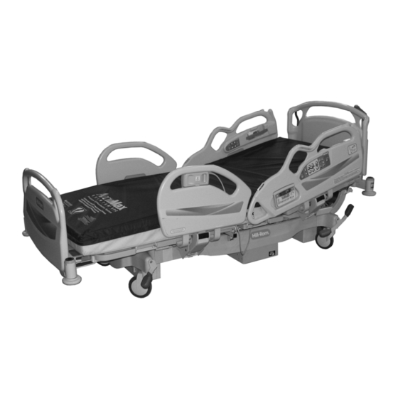
- Page 1 Advanta™ 2 Bed User Manual Product No. P1190 157722 REV 2...
- Page 3 Hill-Rom. The information contained in this manual is subject to change without notice. Hill-Rom makes no commitment to update or keep current, the information contained in this manual. Hill-Rom reserves the right to make changes without notice in design, specifications, and models.
- Page 4 Advanta™ 2 Bed User Manual (157722 REV 2)
-
Page 5: Table Of Contents
Table of Contents Document Symbols........... . . 1 Intended Use . - Page 6 Standard Patient Controls ..........14 Pendant Controls.
- Page 7 Traction Frame Support (P1181) ........30 Patient Helper Support (P1191) .
- Page 8 Advanta™ 2 Bed User Manual (157722 REV 2)
-
Page 9: Document Symbols
Document Symbols This manual contains different typefaces and icons designed to improve readability and increase understanding of its content. For a list of symbols used on the product, see “Product Symbols” on page Note the following examples: • Standard text—used for regular information. •... -
Page 10: Intended Use
This manual provides the information required for normal operation of the Advanta™ 2 Bed from Hill-Rom. Before you operate the bed, be sure to read and understood the contents of this manual. It is important that you read and obey the aspects of safety contained in this manual. Any reference to a side of the bed is from the view of the patient lying in the supine position. -
Page 11: Features
Features Item Description Item Description Speaker Brake/steer pedals Patient control pendant Siderail release mechanism Footboard Caregiver siderail controls Equipment socket Trendelenburg/Reverse Trendelenburg Line-of-Site® Indicator Wall guard Care Grip Hand Hold 6" (152 mm) caster Patient siderail controls 5th wheel or IntelliDrive® Transport Line Manager System (optional) Line-of-Site®... -
Page 12: Standard Features
Standard Features Emergency CPR Control The Emergency CPR control handles are located at the head end of the bed, under each corner of the sleep deck. When activated, the CPR release allows the head section to lower. The CPR release function is gas- assisted to cushion the movement and can be used when power is not available. -
Page 13: Lockout Control
Lockout Control The Lockout control, located on the caregiver siderail control panel, disables the bed articulation functions. To Activate—press and hold the Lockout control, and then press the applicable control. Both patient and caregiver controls are locked out. An LED on the control panel comes on when a lockout is activated. -
Page 14: Knee Up/Down Control
Knee Up/Down Control The Knee Up/Down controls are on the head siderails. The knee section has a maximum travel of 36°. To Activate—press and hold the Knee Up or Knee Down control to raise or lower the knee. The automatic contour feature does not work when using only the Knee Up/Down controls. -
Page 15: Dining Chair® Position
Dining Chair® Position The Dining Chair® Position control allows the caregiver to put the bed in an upright position. The controls are located on the head siderails. When activated, the bed will articulate to a maximum of 65° for the head section, 19° for the knee section, and -12° for the foot section. WARNING: Check at regular times to make sure the patient remains correctly positioned. -
Page 16: Vascular Position
Vascular Position The Vascular Position allows the caregiver to place the patient’s legs above the level of the patient’s sternum without placing the bed in the Trendelenburg position. To Activate—press the Foot Up control. To Return to Flat Position—press the Foot Down control. -
Page 17: Head And Foot Siderails
NOTE: Siderails are intended to be a reminder to the patient of the unit's edges, not a patient-restraining device. When appropriate, Hill-Rom recommends that medical personnel determine the proper methods necessary to make sure a patient remains safely in bed. -
Page 18: Angle Indicators
To Raise • Grasp the siderail by the top, not by the latch area. • Pull the siderail up until it latches into the locked position. A click will be heard when it latches into the locked position. • Once the click is heard, gently pull on the siderail to make sure it is latched correctly. -
Page 19: Line Manager
NOTE: The display on the caregiver pod continuously shows the angle of the head section. Whenever the head section goes below 30°, the display flashes five times. Set the Alarm 1. Raise the head section to the applicable position above 30°. 2. -
Page 20: Care Grip Hand Hold
Care Grip Hand Hold Each head siderail has an ergonomically designed hand hold to assist the patient during ingress and egress, and to position themselves in the bed. Headboard The headboard is located at the head end of the bed and attaches to the head end of the frame. -
Page 21: Equipment Sockets
Equipment Sockets There are four equipment sockets, one at each corner, for the attachment of accessories. The equipment sockets can be used to mount IV poles, ISS poles, traction equipment, and oxygen tank holders. The foot-end equipment sockets should not be used for full traction equipment, but can be used with Buck’s traction. NOTE: The ISS poles require an adapter to be installed before use. -
Page 22: Patient Restraint
When the bed system is docked, place the chest drainage devices on the floor, clear of the bed system to allow space for articulation. Patient Restraint The bed facilitates the use of vest, wrist, waist, and ankle restraints. Hill-Rom makes no recommendation regarding the use of physical restraints. Caregivers should refer to legal restrictions and appropriate facility protocols before physical restraints are used. -
Page 23: Pendant Controls
Pendant Controls To Install the Pendant into the Siderail WARNING: Follow facility protocol for use of patient pendants. WARNING: Make sure the pendant is installed in a location to allow the patient to use all of the functions. WARNING: Only install the pendant in a siderail on the same side as the cable mount is located. Failure to do so could cause patient injury. -
Page 24: Optional Features
Optional Features SideCom® Communication System The SideCom® Communication System provides the following controls: Nurse Call, Entertainment, and Lighting. The SideCom® Communication System connector is located at the head end of the bed. When not connected to the facility, install the dummy plug onto the bed SideCom®... -
Page 25: Bed Exit Alarm System
Bed Exit Alarm System WARNING: The Bed Exit Alarm System is not intended as a substitute for good nursing practices. The Bed Exit Alarm System must be used in conjunction with a sound risk assessment and protocol. The Bed Exit Alarm System control is on the flip-up control pod on the outside of the head end siderails. - Page 26 When the system is armed and it detects movement off the bed, these occur: • An audible alarm comes on. • The Out-of-Bed Mode indicator flashes. • A priority nurse call is sent. The light and alarm continue until the system is turned off, even if the patient lies down on the bed.
-
Page 27: Scale
To Change the Alarm Tone 1. Activate one of the Bed Exit Alarm System Modes. It is recommended to use another caregiver instead of a patient to activate the Bed Exit Alarm System mode. 2. Have the caregiver exit the bed to activate the alarm. 3. -
Page 28: Scale Display On/Off
Scale Display On/Off Press the Weigh control. The scale display becomes active and weighs the patient. The scale display will automatically show the head angle after 3 minutes of no activity. Zero the Scale The bed must be zeroed before the patient is put on the bed. 1. -
Page 29: Auxiliary Outlet (120 V Version Only)
Auxiliary Outlet (120 V Version Only) SHOCK HAZARD: This bed has two power cords. Disconnect both power cords before you service the bed electrical enclosure or auxiliary outlet enclosure. Only facility-authorized persons should service the bed electrical enclosure or auxiliary outlet enclosure. Injury or equipment damage could occur. - Page 30 WARNING: If the bed is stopped on a ramp, or a patient is left unattended, set the brake to avoid unwanted bed movement. Failure to do so can cause personal injury or equipment damage. WARNING: Failure to significantly reduce the speed of travel when you transport freestanding equipment such as portable IV poles along with the bed can cause injury or equipment damage.
-
Page 31: 5Th Wheel Assembly
6. Decreasing pressure on the transport handles will slow the bed. 7. Releasing the enable switch(es) on the transport handles will cause the bed to stop. WARNING: In case of battery or motor power loss, toggle the electronic brake switch to OFF. This permits manual movement of the bed with a deployed, unpowered system. -
Page 32: Navicare® Patient Safety Module
The NaviCare® Patient Safety Module (PSM) is an enterprise system that connects and monitors Hill-Rom® beds and surfaces. The system sends bed and surface data to network applications for caregivers to view and receive alerts. For complete operational instructions for the NaviCare®... -
Page 33: Deactivate The Safeview® Alerts
The SafeView® Alerts show a steady green when the Bed Exit Alarm System is active and all of the conditions below are met. If one or more of these conditions are not met, the Alerts flash yellow: • The bed is in the low position. •... -
Page 34: Optional Patient Controls
2. Press, and hold, these controls at the same time for five seconds: Knee Up, Knee Down, Bed Up, and Bed Down. The Alerts will flash green for three seconds to let you know the configuration is set. To make sure the Alerts operate as configured, do as follows: 1. -
Page 35: Channel Control
Channel Control The channel control allows the patient to change channels on the television or stations on the radio in the room. Music Control The music control allows the patient to turn on and off the radio in the room. Television Control The television control allows the patient to turn on and off the television in the room. -
Page 36: Accessories
Accessories Part Number Description P2217 IV Pole P736EA1 Mattress foot pad extender See page 29 Mattress P158 Infusion Support System (ISS) transfer pole P27601 Oxygen tank holder, E-size P163 ISS socket adapter P1181 Traction frame support P1191 Patient helper support P1176 Patient helper, fixed position, kit P1177A... -
Page 37: Mattress Foot Pad Extender
Synergy® Air Elite Low Airloss Alternating Therapy System—P004651 • TempurPedic® Mattress—P3584EA-1 • ZoneAire® Sleep Surface System—P1410EB04/P46209 Refer to the applicable product documentation for user instructions. It is recommended to use loose fitting, knitted sheets with the mattresses from Hill-Rom. Advanta™ 2 Bed User Manual (157722 REV 2) -
Page 38: Oxygen Tank Holder, E-Size (P27601)
Oxygen Tank Holder, E-Size (P27601) WARNING: If the oxygen tank holder is placed at the foot end of the bed, make sure the Knee Up/Down controls are locked out. Failure to do so can cause caregiver, patient, or visitor injury if the foot section fully lowers and the holder becomes dislodged from the bed. -
Page 39: Patient Helper (P1176 And P1177A)
Patient Helper (P1176 and P1177A) The Patient Helper (P1176 and P1177A) installs in the equipment sockets at the head end of the bed. The P1176 is a fixed position patient helper and the P1177A is an adjustable position patient helper. WARNING: Do not exceed the load capacity of the Patient Helper (P1176 and P1177A). -
Page 40: Patient Helper Positioning (P1177A)
Patient Helper Positioning (P1177A) WARNING: The Patient Helper in the patient transfer position is designed to help the patient lift some of his/her weight so as to assist the nursing staff with their work. This position is not designed to allow patients to transfer themselves alone. -
Page 41: Vip Headboard (P921190Ha And P931190Ha) And Footboard (P921170Fa And P931170Fa)
VIP Headboard (P921190HA and P931190HA) LibertyHill™ Headboard and Footboard (P921170FA and P931170FA) and Footboard The VIP headboards are available in two styles: FreedomHill™ P921190HA (P931190HA) and LibertyHill™ (P921190HA). The VIP footboards are available in two styles: FreedomHill™ (P931170FA) and LibertyHill™ (P921170FA). WARNING: Install the headboards and footboards correctly. -
Page 42: Safety Tips
Safety Tips Bed Positions WARNING: It is recommended that the unit be in the low position when the patient is unattended. This may reduce the severity of any resultant injuries from patient falls. WARNING: When a patient’s condition (such as disorientation due to medication or clinical condition) could lead to patient entrapment, the sleep deck should be left in the flat and lowest position while unattended (except when required otherwise by medical staff for special or particular circumstances). -
Page 43: Electricity
Gently pull on the siderail once the click is heard to make sure the siderail is latched in position. Siderails are intended to be a reminder, not a patient restraining device. Hill-Rom recommends that the appropriate medical personnel determine the level of restraint necessary to make sure a patient will remain safely in bed. -
Page 44: Electricity-Beds With An Auxiliary Outlet
WARNING: If the integrity of the external protective earth conductor is in doubt, operate the bed from its internal electrical power source. Failure to do so could cause personal injury. CAUTION: This device meets all applicable requirements for electromagnetic compatibility per IEC 60601- 1-2. -
Page 45: Parts And Accessories
Parts and Accessories Only use parts and accessories from Hill-Rom. Do not modify the bed system without authorization from Hill-Rom. Operating Bed/Surface Precautions WARNING: Do not operate the bed in the presence of flammable gas or vapors. Doing so could cause personal injury or equipment damage. -
Page 46: Flammability
Flammability WARNING: Patients should not be allowed to smoke in bed. Sheets and pillows generally do not have flame resistant properties. Personal injury or equipment damage could occur. Reduce the possibility of fires by observing fire prevention rules and regulations. Refer to the mattress documentation for all applicable fire codes. -
Page 47: Transport Position
Transport Position WARNING: Put the bed in the lowest position for transportation. Failure to do so could cause injury or damage. Make sure the bed is in the lowest position before you transport the bed. See “Bed Up/Down Control” on page 5. Advanta™... -
Page 48: Clean And Disinfect
Clean and disinfect surfaces with nano Ag+® Technology as you would other surfaces. This product is not intended to protect users or others against bacteria, viruses, germs, or other disease organisms. Always disinfect Hill-Rom surfaces thoroughly after each use according to facility protocol. Clean 1. -
Page 49: Disinfect
4. Clean the bed. Give special attention to these areas: • Headboard—thoroughly clean as this is a high-touch area • Footboard—remove from the bed, and thoroughly clean as this is a high-touch area • Siderails—thoroughly clean the high-touch areas such as the upper and under sides of the siderail releases, pendants, and patient controls •... -
Page 50: Cleaning Wood Headboard And Footboard
Cleaning Wood Headboard and Footboard The wood headboard and footboard are treated with a resin-based sealer and finish that provide resistance to abrasion, staining, fluids, and fire. Many disinfectant/cleansers have a “softening” effect on any painted or finished surface if used in high concentrations. Clean the head- and footboards with a soft cloth dampened with a suitable solution, followed by use of a dry cloth. -
Page 51: Preventive Maintenance
Preventive Maintenance WARNING: Only facility-authorized personnel should service the bed. Servicing by unauthorized personnel could cause personal injury or equipment damage. The bed requires an effective maintenance program. We recommend that you do annual preventive maintenance (PM) and testing for Joint Commission on Accreditation of Healthcare Organizations (JCAHO). -
Page 52: Product Symbols
Product Symbols The following symbols are used on the bed: Symbol Description Type B applied part according to IEC 60601-1 (UL 60601-1). According to IEC 60529, Rating for protection against fluid ingress and identified as equipment that is protected against spraying and IPX4 splashing water. - Page 53 Symbol Description Knee Up/Down control—Raises and lowers the knee section of the bed. Battery control—Activates the battery. Indicates battery charge. Enable control—Enables the Bed Exit System control pod functions. (Located on the scale control pod) Trendelenburg control—Enables the Trendelenburg function on the bed.
- Page 54 Symbol Description Foot Up/Down control—Raises or lowers the foot section on the bed. Room Light control—Turns the room light on and off. (Patient control pendant only) Reading Light control—Turns the reading light on and off. (Patient control pendant only) Music control—Turns the radio on and off. (Patient control pendant only) Television control—Turns the television on and off.
- Page 55 Symbol Description Do Not Use with Oxygen Tents—Indicates that oxygen tents are not to be used. Use oxygen administering equipment of the nasal, mask, or ventilator type only. Bed Not Down Indicator—Illuminates when the bed is not in the low-low position.
- Page 56 Symbol Description Patient Position Mode—Comes on when a patient moves towards either siderail or moves away from the head section such as by sit- ting up in bed. Bed Exiting Mode alarm—Comes on when a patient moves away from the center of the bed towards an exit point. Out-of-Bed Mode alarm—Comes on when the patient's weight shifts significantly off the frame of the bed.
-
Page 57: Specifications
Specifications Product Identification Product Number Description P1190A The Advanta™ 2 Bed Dimensions Feature Dimension Maximum length 100" (254 cm) Maximum width (siderails stored) 40" (102 cm) Maximum width (siderails up) 40" (102 cm) Recommended Mattress dimensions: Mattress width 36" (91.4 cm) Mattress length 84"... - Page 58 Environmental Conditions for Transport and Storage Condition Range Temperature -40°F to 158°F (-40°C to 70°C) Relative humidity 10% to 95%, non-condensing Pressure 70 kPa to 106 kPa Nurse Call Connection Requirements For information about the Nurse Call connection requirements, refer to the SideCom® Communication Sys- tem Design and Application Manual (DS059).
- Page 59 Guidance and Manufacturer's Declaration—Electromagnetic Emissions The Advanta™ 2 Bed model P1190 is intended for use in the electromagnetic environment specified below. The customer or the user of the model P1190 should make sure it is used in such an environment. Emissions Test Compliance Electromagnetic Environment—Guidance...
- Page 60 Guidance and Manufacturer's Declaration - Electromagnetic Emissions The Advanta™ 2 Bed model P1190 is intended for use in the electromagnetic environment specified below. The customer or the user of the model P1190 should make sure it is used in such an environment. Immunity Test...
Need help?
Do you have a question about the P1190 and is the answer not in the manual?
Questions and answers