
Related Manuals for Hill-Rom Resident LTC Bed


Summary of Contents for Hill-Rom Resident LTC Bed
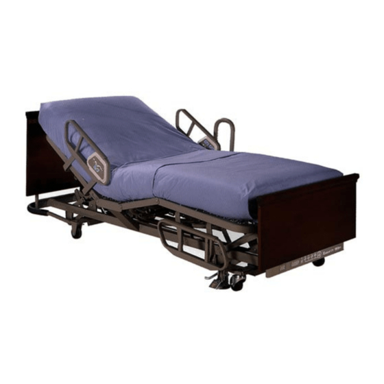
- Page 1 SERVICE MANUAL Resident Errata man136rc-e2 From Hill-Rom ® Product No. P870 For Parts Or Technical Assistance man136rc USA 1-800-445-3720 Canada 1-800-267-2337...
- Page 2 Resident LTC Bed Service Manual Revisions Revision Letter Pages Affected Date Original Issue December, 1996 January, 1997 July, 1997 September, 1997 man136rc Resident LTC Bed Service Manual (man136rc) Page i...
- Page 3 E. I. du Pont, de Nemours & Co. The information contained in this manual is subject to change without notice. Hill-Rom makes no commitment to update or keep current, the information contained in this manual.
-
Page 4: Table Of Contents
Table of Contents Chapter 1: Introduction Purpose of this Manual ..........1 - 5 Who Should Use This Manual . - Page 5 Table of Contents Mattress Stop ..........1 - 13 Mattress Configurations .
- Page 6 Table of Contents Sleep Surface Support Frame ........1 - 23 Mattress Stop .
- Page 7 Table of Contents Chapter 2: Troubleshooting Procedures Getting Started ........... . 2 - 3 Troubleshooting the Resident LTC Manual Drive Bed.
- Page 8 Table of Contents Head ............3 - 8 Knee .
- Page 9 Table of Contents Removal ........... . . 4 - 27 Replacement .
- Page 10 Table of Contents Bumper Assembly..........4 - 52 Removal .
- Page 11 Table of Contents General Cleaning ..........6 - 3 Steam Cleaning .
- Page 12 Table of Contents Installation ........... 7 - 12 Heirloom Head and Foot Panels (P4072) .
- Page 13 Table of Contents NOTES: Page xii Resident LTC Bed Service Manual (man136rc)
- Page 14 Chapter 1 Introduction Chapter Contents Purpose of this Manual ..........1 - 5 Who Should Use This Manual .
- Page 15 Chapter 1: Introduction Bumper ........... 1 - 12 IV Rod Sockets .
- Page 16 Chapter 1: Introduction Siderails ..........1 - 23 Bumper .
- Page 17 Chapter 1: Introduction Model Identification ..........1 - 31 Safety Tips .
-
Page 18: Chapter 1: Introduction
Purpose of this Manual Chapter 1: Introduction Purpose of this Manual This manual provides information needed to operate and maintain the Hill- ® Resident LTC (long term care) bed. Both the manual and electric drive versions of the bed are covered. Additionally, a complete parts list for ordering replacement components is included in chapter 5. -
Page 19: Chapter 4: Removal, Replacement, And Adjustment Procedures
LTC bed components. Once again, the manual and electric drive versions of the bed are addressed separately. Chapter 5: Parts List ® Chapter 5 contains Hill-Rom ’s warranty, replacement part ordering procedure, exchange policy, recommended spare parts lists, and illustrated parts lists. -
Page 20: Typographical Conventions Used In This Manual
Typographical Conventions Used in this Manual Chapter 1: Introduction Typographical Conventions Used in this Manual This manual contains different typographical conventions designed to enhance readability and understanding of its content. Note the following examples: • Standard text—used for standard text throughout the manual. •... -
Page 21: Introduction To The Resident
Introduction to the Resident LTC Manual Drive Bed Chapter 1: Introduction Introduction to the Resident LTC Manual Drive Bed Operating Precautions Before operating the bed, ensure that you read and fully understand the contents of this manual. It is important that you strictly adhere to the safety information contained within. - Page 22 Introduction to the Resident LTC Manual Drive Bed Chapter 1: Introduction Figure 1-5. Head Section Position of the Manual Drive Bed Head end Foot end m136b005 Figure 1-6. Knee Section Position of the Manual Drive Bed Head end Foot end m136_110 Resident LTC Bed Service Manual (man136rc)
-
Page 23: Resident Tm Ltc Manual Drive Bed Specifications
Resident LTC Manual Drive Bed Specifications Chapter 1: Introduction Figure 1-7. Knee Gatch (Foot Section) Position of the Manual Drive Bed Foot end Head end m136_111 Resident LTC Manual Drive Bed Specifications Physical Description See table 1-1 on page 1-10 for Resident LTC manual drive bed specifications. -
Page 24: Head Section Inclination
Resident LTC Manual Drive Bed Specifications Chapter 1: Introduction NOTE: The head section, knee section, and hilow functions of the Resident manual drive bed are adjusted by manipulating the hand cranks located at the foot end of the bed. WARNING: Electric or manual drive bed mechanisms can cause serious injury if operated improperly. -
Page 25: Brakes
Resident LTC Manual Drive Bed Specifications Chapter 1: Introduction Brakes The brakes are located on both sides of the swivel caster frame assembly at the foot end of the bed. Some models have individually operated brakes and require that both pedals be pressed and released separately. Siderails Siderails are located on both sides of the Resident LTC manual drive bed at... -
Page 26: Mattress Stop
Resident LTC Manual Drive Bed Specifications Chapter 1: Introduction Mattress Stop A separate mattress stop is not available on the manual drive version of the Resident LTC manual drive bed. The foot panel acts as a mattress stop on this version preventing the mattress from sliding towards the foot end of the bed. - Page 27 Resident LTC Manual Drive Bed Specifications Chapter 1: Introduction The head section can be adjusted by turning the right crank handle (A), the knee section can be adjusted by turning the left crank handle (B), and the hilow function is adjusted by turning the middle crank handle (C) (see figure 1-8 on page 1-14).
-
Page 28: General Operation Of The Resident
General Operation of the Resident LTC Manual Drive Bed Chapter 1: Introduction General Operation of the Resident LTC Manual Drive Bed Siderail Operation WARNING: Siderails are visual reminders for residents that identify the location of the edge of the bed. They are not intended for use as a restraint device. -
Page 29: Bed Positions
General Operation of the Resident LTC Manual Drive Bed Chapter 1: Introduction Bed Positions WARNING: Manual drive bed mechanisms can cause serious injury. Operate the bed only when persons are clear of the mechanisms. Hilow To raise the bed, locate the middle hand crank at the foot end of the bed. Turn the handle clockwise until the desired height is achieved. -
Page 30: Brakes
General Operation of the Resident LTC Manual Drive Bed Chapter 1: Introduction Brakes WARNING: Set the brakes, and leave the bed in the low position when the resident is unattended. A resident might use the bed for support when getting on or off of the sleep surface. -
Page 31: Introduction To The Resident Tm Ltc Electric Drive Bed
Introduction to the Resident LTC Electric Drive Bed Chapter 1: Introduction Introduction to the Resident LTC Electric Drive Bed Operating Precautions Before operating the bed, ensure that you read and fully understand the contents of this manual. It is important that you strictly adhere to the safety information contained within. - Page 32 Introduction to the Resident LTC Electric Drive Bed Chapter 1: Introduction Figure 1-10. Automatic Contour Position of the Electric Drive Bed Head end Foot end m136_003 Figure 1-11. Head Section Position of the Electric Drive Bed Head end Foot end m136_005 Resident LTC Bed Service Manual (man136rc)
- Page 33 Introduction to the Resident LTC Electric Drive Bed Chapter 1: Introduction Figure 1-12. Knee Section Position of the Electric Drive Bed Head end Foot end m136_004 Figure 1-13. Knee Gatch (Foot Section) Position of the Electric Drive Bed Head end Foot end m136_006 Page 1 - 20...
-
Page 34: Resident Tm Ltc Electric Drive Bed Specifications
Resident LTC Electric Drive Bed Specifications Chapter 1: Introduction Resident LTC Electric Drive Bed Specifications Physical Description See table 1-3 on page 1-21 for Resident LTC electric drive bed specifications. Table 1-3. Resident LTC Electric Drive Bed Specifications Feature Dimension Overall length in high position 95 1/4"... -
Page 35: Head Angle Indicators
Resident LTC Electric Drive Bed Specifications Chapter 1: Introduction optional resident control panel on the inside of both head end siderails can also be used in the electric drive version to adjust the head section. Head Angle Indicators The head angle indicator decals are located at both sides of the bed on the sleep surface. -
Page 36: Brakes
Resident LTC Electric Drive Bed Specifications Chapter 1: Introduction Brakes The brakes are located on both sides of the swivel caster frame assembly at the foot end of the bed. Some models have individually operated brakes and require that both pedals be pressed and released separately. Siderails Siderails are located on both sides of the Resident LTC electric drive bed at... -
Page 37: Mattress Stop
Resident LTC Electric Drive Bed Specifications Chapter 1: Introduction is 36" x 80" (91.4 cm x 203.2 cm). The outer surfaces of the panels are formed down to prevent sharp edges. Mattress Stop A mattress stop is located at the foot end of the spring frame. In its raised position, the mattress stop prevents the mattress from sliding towards the foot end of the bed. -
Page 38: Handset Control
Resident LTC Electric Drive Bed Specifications Chapter 1: Introduction The Resident LTC electric drive bed operates on 120V AC, 60 Hz, single phase power. The electrical power system is mechanically insulated from the metal parts of the bed. No additional electrical components, such as isolation transformers, are required to make this bed meet applicable electrical codes. -
Page 39: Motor Actuators
Resident LTC Electric Drive Bed Specifications Chapter 1: Introduction The control box lockout is located at the foot end of the bed. The position of each control knob on the control lockout is pictorially labeled to indicate each governing function and the locked/unlocked position. See “Automatic Contour”... -
Page 40: Ul Classification
Resident LTC Electric Drive Bed Specifications Chapter 1: Introduction CAUTION: The duty cycle (continuous operation) of any actuator should not be more than 10%. Otherwise, damage to the equipment can occur. UL Classification The Resident LTC electric drive bed is approved to UL 2601-1 standards and is classified as Class II double insulated electrical equipment. -
Page 41: General Operation Of The Resident Ltc Electric Drive Bed
General Operation of the Resident LTC Electric Drive Bed Chapter 1: Introduction General Operation of the Resident LTC Electric Drive Bed Siderail Operation WARNING: Siderails are visual reminders for residents that identify the location of the edge of the bed. They are not intended for use as a restraint device. -
Page 42: Bed Positions
General Operation of the Resident LTC Electric Drive Bed Chapter 1: Introduction Bed Positions SHOCK HAZARD: One of the risks associated with the use of electrical equipment includes the potential for electrical shock. Train and educate personnel on the risks associated with electrical equipment. WARNING: Electric or manual drive bed mechanisms can cause serious injury if operated improperly. -
Page 43: Automatic Contour
General Operation of the Resident LTC Electric Drive Bed Chapter 1: Introduction Automatic Contour Lock out the automatic contour feature on the electric drive version as follows: • Turn the knee section control lockout to the locked position. • Turn the automatic contour control lockout to the locked position. •... -
Page 44: Mattress Stop
Model Identification Chapter 1: Introduction Apply the brakes by depressing the brake pedal(s) with your foot. Release the brakes by depressing the release arm next to the brake pedal. Mattress Stop To raise the mattress stop, lift upward until the notches in the bent legs of the stop engage the slots in the spring frame. -
Page 45: Safety Tips
Safety Tips Chapter 1: Introduction Safety Tips SHOCK HAZARD: One of the risks associated with the use of electrical equipment includes the potential for electrical shock. Train and educate personnel on the risks associated with electrical equipment. SHOCK HAZARD: Unplug the bed from its power source before servicing or cleaning the bed. - Page 46 Safety Tips Chapter 1: Introduction WARNING: Siderails are visual reminders for residents that identify the location of the edge of the bed. They are not intended for use as a restraint device. Appropriate medical personnel must determine the level of restraint necessary to ensure a resident will remain safely in bed.
- Page 47 Safety Tips Chapter 1: Introduction CAUTION: Removing the bumper assembly could cause damage to the bed or facility. CAUTION: Overtightening the mounting screws can crack the P.C. boards. CAUTION: The hilow motor actuator connecting pin must align with its receptacle in the control box.
- Page 48 Safety Tips Chapter 1: Introduction CAUTION: Do not drop the printed circuit (P.C.) boards against the siderail or the sleep surface frame. Damage to the equipment may occur. CAUTION: Use care when removing the siderail labels to prevent damage. Replace damaged labels with new ones. CAUTION: Do not lower the bed frame while the trapeze support is attached to the bed.
-
Page 49: Warning And Caution Labels
Warning and Caution Labels Chapter 1: Introduction Warning and Caution Labels Figure 1-14. Warning and Caution Labels at the Head End of the Resident Manual/Electric Drive Bed m136_007 m136_008 Page 1 - 36 Resident LTC Bed Service Manual (man136rc) - Page 50 Warning and Caution Labels Chapter 1: Introduction Figure 1-15. Warning and Caution Label at the Foot End of the Resident LTC Electric Drive Bed m136_009 Figure 1-16. Serial Number Data Plate m136_161 Resident LTC Bed Service Manual (man136rc) Page 1 - 37...
- Page 51 Warning and Caution Labels Chapter 1: Introduction NOTES: Page 1 - 38 Resident LTC Bed Service Manual (man136rc)
- Page 52 Chapter 2 Troubleshooting Procedures Chapter Contents Getting Started ........... . 2 - 3 Troubleshooting the Resident LTC Manual Drive Bed.
- Page 53 Chapter 2: Troubleshooting Procedures NOTES: Page 2 - 2 Resident LTC Bed Service Manual (man136rc)
-
Page 54: Getting Started
Perform the Final Actions after the Function Checks to verify the repair. ® If troubleshooting procedures do not isolate the problem, call Hill-Rom Technical Support at (800) 445-3720 for assistance. WARNING: Only facility-authorized maintenance personnel should troubleshoot the Resident LTC bed. -
Page 55: Troubleshooting The Resident
Troubleshooting the Resident LTC Manual Drive Bed Chapter 2: Troubleshooting Procedures Troubleshooting the Resident LTC Manual Drive Bed Initial Actions Manual Drive Model — Use Initial Actions to gather information from operators concerning problems with the Resident LTC bed. Note symptoms or other information concerning the problem that the operator identifies. -
Page 56: Function Checks-Manual Drive Model
Function Checks—Manual Drive Model Chapter 2: Troubleshooting Procedures Function Checks Manual Drive Model — 1. Initial Actions have been performed. ↓ → Go to “Initial Actions—Manual Drive Model” on page 2-4. 2. Inspect the brake pads for wear. Both brake pads are in good condition. ↓... - Page 57 Function Checks—Manual Drive Model Chapter 2: Troubleshooting Procedures 5. Raise, lower and store the siderails (see figure 2-2 on page 2-6). The siderails move without binding or requiring excessive force, and the latch locks the siderail into position. ↓ → Go to RAP 2.2. Figure 2-2.
- Page 58 Function Checks—Manual Drive Model Chapter 2: Troubleshooting Procedures 8. Turning the hilow (middle) hand crank counterclockwise, lower the bed to its low position. The bed lowers evenly to its low position. ↓ → Go to RAP 2.4. 9. Turning the head (right) hand crank clockwise, raise the head section to its greatest inclined position.
-
Page 59: Final Actions-Manual Drive Model
Final Actions—Manual Drive Model Chapter 2: Troubleshooting Procedures Final Actions Manual Drive Model — 1. Complete the required preventive maintenance procedures. See “Preventive Maintenance Schedule—Manual Drive Model” on page 6-7. 2. Complete all required administrative tasks. Page 2 - 8 Resident LTC Bed Service Manual (man136rc) -
Page 60: Troubleshooting The Resident
Troubleshooting the Resident LTC Electric Drive Bed Chapter 2: Troubleshooting Procedures Troubleshooting the Resident LTC Electric Drive Bed Initial Actions Electric Drive Model — Use Initial Actions to gather information from operators concerning problems with the Resident LTC bed. Note symptoms or other information concerning the problem that the operator identifies. -
Page 61: Function Checks-Electric Drive Model
Function Checks—Electric Drive Model Chapter 2: Troubleshooting Procedures Function Checks Electric Drive Model — 1. Initial Actions have been performed. ↓ → Go to “Initial Actions—Electric Drive Model” on page 2-9. 2. Inspect the brake pads for wear. Both brake pads are in good condition. ↓... - Page 62 Function Checks—Electric Drive Model Chapter 2: Troubleshooting Procedures 5. Raise, lower and store the siderails (see figure 2-4 on page 2-11). The siderails move without binding or requiring excessive force, and the latch locks the siderail into position. ↓ → Go to RAP 2.2. Figure 2-4.
- Page 63 Function Checks—Electric Drive Model Chapter 2: Troubleshooting Procedures Figure 2-5. Handset Control (Hilow Actuator Control) m136_012 8. Press the HI/LO Up button (A) on the handset control to raise the bed to its high position (see figure 2-5 on page 2-12). The bed rises evenly to its high position.
- Page 64 Function Checks—Electric Drive Model Chapter 2: Troubleshooting Procedures Figure 2-6. Caregiver Siderail Control Panel (Hilow Actuator Controls) m136_013 11. Press the HEAD Up button (A) on the handset control panel to raise the head section to its greatest inclined position (see figure 2-7 on page 2-13). The head of the bed raises fully and evenly to approximately 65 indicated by the head angle indicator decals located on both sides of the bed.
- Page 65 Function Checks—Electric Drive Model Chapter 2: Troubleshooting Procedures 13. Repeat steps 11 and 12 using the optional resident siderail control panel (if equipped) (see figure 2-8 on page 2-14). After pressing the HEAD Up button (A), the head section rises evenly to its high position. After pressing the HEAD Down button (B), the head section lowers evenly to its low position.
- Page 66 Function Checks—Electric Drive Model Chapter 2: Troubleshooting Procedures Figure 2-9. Handset Control (Knee Actuator Controls) m136_012 16. Repeat steps 14 and 15 using the optional resident siderail control panel (if equipped) (see figure 2-8 on page 2-14). After pressing the KNEE Up button (C), the bed rises evenly to its high position.
- Page 67 Function Checks—Electric Drive Model Chapter 2: Troubleshooting Procedures 18. With the bed in the automatic contour position (see figure 2-10 on page 2-16), operate the head down function. Pressing the HEAD Down button (with the head section inclined above 15 ) causes the head section only to lower.
- Page 68 Function Checks—Electric Drive Model Chapter 2: Troubleshooting Procedures Figure 2-11. Control Lockout Box m136_015 20. Turn the control lockout box knobs (one at a time) to the unlocked position. The controlling function operates correctly. ↓ → Go to RAP 2.11. 21.
-
Page 69: Final Actions-Electric Drive Model
Final Actions—Electric Drive Model Chapter 2: Troubleshooting Procedures Final Actions Electric Drive Model — 1. Complete the required preventive maintenance procedures. See “Preventive Maintenance Schedule—Electric Drive Model” on page 6-9. 2. Complete all required administrative tasks. Page 2 - 18 Resident LTC Bed Service Manual (man136rc) -
Page 70: Reduced Braking Ability
2.1 Reduced Braking Ability Chapter 2: Troubleshooting Procedures Reduced Braking Ability Individually Operated Brakes 1. Press the brake pedal (A) (see figure 2-12 on page 2-19). The brake locks, and the bed does not move. ↓ → Go to step 3. 2. -
Page 71: Siderail Mechanical Malfunction
2.2 Siderail Mechanical Malfunction Chapter 2: Troubleshooting Procedures Siderail Mechanical Malfunction 1. The siderail moves smoothly from/to the stored position. ↓ → Check that the slide rods are not bent, guide pins (A) enter the aligned holes through the channel assembly, and engage the holes in strap (B) (see figure 2-13 on page 2-20). - Page 72 2.2 Siderail Mechanical Malfunction Chapter 2: Troubleshooting Procedures 4. Push inward on the siderail release (D). This unlocks the siderail so it can be lowered and rotated smoothly to the down position. ↓ → Go to step 6. 5. The strap portion of the siderail arm assembly is not bent or distorted. ↓...
-
Page 73: Loose, Bent, Or Missing Hardware
2.3 Loose, Bent, or Missing Hardware Chapter 2: Troubleshooting Procedures Loose, Bent, or Missing Hardware 1. Visual inspection indicates that there are no loose, bent, or missing screws, nuts, bolts, or washers on the lower frame assemblies, the caster frame assemblies, or the sleep surface frame assembly. -
Page 74: Manual Hilow Function Does Not Raise Or Lower Correctly
2.4 Manual Hilow Function Does Not Raise or Lower Correctly Chapter 2: Troubleshooting Procedures Manual Hilow Function Does Not Raise or Lower Correctly 1. The bolt and nut securing the hilow crank handle to the hilow drive assembly are present and secure. ↓... - Page 75 2.4 Manual Hilow Function Does Not Raise or Lower Correctly Chapter 2: Troubleshooting Procedures 3. The manual hilow drive screw assembly is well lubricated and turns freely. ↓ → Lightly lubricate the manual hilow drive screw assembly with P/N 8252 M-1 penetrating oil. This solves the problem.
-
Page 76: Manual Head Section Does Not Raise Or Lower Correctly
2.5 Manual Head Section Does Not Raise or Lower Correctly Chapter 2: Troubleshooting Procedures Manual Head Section Does Not Raise or Lower Correctly 1. The bolt and nut securing the head crank handle to the head drive assembly are present and secure. ↓... - Page 77 2.5 Manual Head Section Does Not Raise or Lower Correctly Chapter 2: Troubleshooting Procedures 3. The manual head drive screw assembly is well lubricated and turns freely. ↓ → Lightly grease the manual head drive screw assembly with P/N SA3351 grease. This solves the problem.
-
Page 78: Manual Knee Section Does Not Raise Or Lower Correctly
2.6 Manual Knee Section Does Not Raise or Lower Correctly Chapter 2: Troubleshooting Procedures Manual Knee Section Does Not Raise or Lower Correctly 1. The bolt and nut securing the knee crank handle to the knee drive assembly are present and secure. ↓... - Page 79 2.6 Manual Knee Section Does Not Raise or Lower Correctly Chapter 2: Troubleshooting Procedures 3. The manual knee drive screw assembly is well lubricated and turns freely. ↓ → Lightly grease the manual knee drive screw assembly with P/N SA3351 grease. This solves the problem.
-
Page 80: Electric Hilow Does Not Raise Or Lower Correctly
2.7 Electric Hilow Does Not Raise or Lower Correctly Chapter 2: Troubleshooting Procedures Electric Hilow Does Not Raise or Lower Correctly 1. The bed is plugged into the appropriate power source. ↓ → Connect a good power cord to the wall outlet (see figure 2-34 on page 2-44). - Page 81 2.7 Electric Hilow Does Not Raise or Lower Correctly Chapter 2: Troubleshooting Procedures Figure 2-21. Hilow Controls m136_020 m136_019 4. The power/hilow cable (A) is firmly connected to its receptacle on the control box, and the routing to the control lockout box shows no visible damage (see figure 2-22 on page 2-30).
- Page 82 → Replace the hilow motor actuator (see “Hilow Motor Actuator” on page 4-16). 10. Eliminate the interference with the hilow operation of the bed. This solves the problem. ↓ → Call Hill-Rom ® Technical Support at (800) 445-3720. 11. Go to “Final Actions—Electric Drive Model” on page 2-18. Resident...
-
Page 83: Electric Head Section Does Not Raise Or Lower Correctly
2.8 Electric Head Section Does Not Raise Or Lower Correctly Chapter 2: Troubleshooting Procedures Electric Head Section Does Not Raise Or Lower Correctly 1. The bed is plugged into the appropriate power source. ↓ → Connect a good power cord to the wall outlet (see figure 2-34 on page 2-44). - Page 84 2.8 Electric Head Section Does Not Raise Or Lower Correctly Chapter 2: Troubleshooting Procedures Figure 2-24. Head Controls m136_023 4. The head motor actuator cable (A) is firmly connected to its receptacle on the control box (on top of the hilow motor actuator), and the routing to the control lockout box shows no visible damage (see figure 2-25 on page 2-33).
- Page 85 Actuator” on page 4-18). 10. Eliminate the interference with the head movement of the bed. This solves the problem. ↓ → Call Hill-Rom ® Technical Support at (800) 445-3720. 11. Go to “Final Actions—Electric Drive Model” on page 2-18. Page 2 - 34...
-
Page 86: Electric Knee Section Does Not Raise Or Lower Correctly
2.9 Electric Knee Section Does Not Raise Or Lower Correctly Chapter 2: Troubleshooting Procedures Electric Knee Section Does Not Raise Or Lower Correctly 1. The bed is plugged into the appropriate power source. ↓ → Connect a good power cord to the wall outlet (see figure 2-34 on page 2-44). - Page 87 2.9 Electric Knee Section Does Not Raise Or Lower Correctly Chapter 2: Troubleshooting Procedures Figure 2-27. Knee Controls m136_026 4. The knee motor actuator cable (A) is firmly connected to its receptacle on the control box (on top of the hilow motor actuator), and the routing to the control lockout shows no visible damage (see figure 2-28 on page 2-36).
- Page 88 Motor Actuator” on page 4-20). 10. Eliminate the interference with the knee movement of the bed. This solves the problem. ↓ → Call Hill-Rom ® Technical Support at (800) 445-3720. 11. Go to “Final Actions—Electric Drive Model” on page 2-18.
-
Page 89: 2.10 Automatic Contour Does Not Function Correctly
2.10 Automatic Contour Does Not Function Correctly Chapter 2: Troubleshooting Procedures 2.10 Automatic Contour Does Not Function Correctly 1. The bed is plugged into the appropriate power source. ↓ → Connect a good power cord to the wall outlet (see figure 2-34 on page 2-44). - Page 90 2.10 Automatic Contour Does Not Function Correctly Chapter 2: Troubleshooting Procedures 4. Pressing the HEAD Down button with the head section inclined above 15 causes only the head section to lower. Continuing to press the HEAD Down button causes the knee section to begin lowering. Lowering of both sections continues (with HEAD Down pressed) until the flat position is reached.
- Page 91 2.10 Automatic Contour Does Not Function Correctly Chapter 2: Troubleshooting Procedures 7. Turn the control lockout knob for the automatic contour function (B) to the locked position (see figure 2-29 on page 2-38). This prevents automatic contour operation. Turn the control lockout knob to the unlocked position. This allows automatic contour operation.
-
Page 92: 2.11 Control Lockout Does Not Function Correctly
2.11 Control Lockout Does Not Function Correctly Chapter 2: Troubleshooting Procedures 2.11 Control Lockout Does Not Function Correctly 1. The bed is plugged into the appropriate power source. ↓ → Connect a good power cord to the wall outlet (see figure 2-34 on page 2-44). - Page 93 2.11 Control Lockout Does Not Function Correctly Chapter 2: Troubleshooting Procedures 5. Press the Up or Down buttons on the handset or both optional siderail controls (if available). This creates a relay clicking sound in the control box (on top of the hilow motor actuator). ↓...
- Page 94 Unplug the bed from its power source before unplugging any cables from the control lockout, or from the control box. An electrical shock hazard exists. ↓ → Call Hill-Rom ® Technical Support at (800) 445-3720. Figure 2-33. Control Lockout Cable Connection at Control Box m136_032 11.
-
Page 95: 2.12 None Of The Electrical Functions Operate
2.12 None Of The Electrical Functions Operate Chapter 2: Troubleshooting Procedures 2.12 None Of The Electrical Functions Operate 1. The bed is plugged into the appropriate power source. ↓ → Connect the power cord (A) to the wall outlet (see figure 2-34 on page 2-44). - Page 96 → Connect the cables, and replace any that are damaged. This solves the problem. ↓ → Call Hill-Rom ® Technical Support at (800) 445-3720. 5. Press the Up and Down buttons for each function on the handset and on the optional siderail controls (if available).
-
Page 97: 2.13 Siderail Control/Handset Control Does Not Operate Correctly
2.13 Siderail Control/Handset Control Does Not Operate Correctly Chapter 2: Troubleshooting Procedures 2.13 Siderail Control/Handset Control Does Not Operate Correctly 1. The optional siderail control cables (A) (if available) and the handset control cable (B) are firmly connected to their respective receptacles on the control lockout box and are in good condition (see figure 2-32 on page 2-42). - Page 98 Chapter 3 Theory of Operation Chapter Contents Electrical System Block Diagram........3 - 3 Siderail Control Schematic .
-
Page 99: Chapter 3: Theory Of Operation
Chapter 3: Theory of Operation NOTES: Page 3 - 2 Resident LTC Bed Service Manual (man136rc) -
Page 100: Electrical System Block Diagram
Electrical System Block Diagram Chapter 3: Theory of Operation Electrical System Block Diagram Figure 3-1. Electrical System Block Diagram m136_046 Resident LTC Bed Service Manual (man136rc) Page 3 - 3... -
Page 101: Siderail Control Schematic
Siderail Control Schematic Chapter 3: Theory of Operation Siderail Control Schematic Figure 3-2. Siderail Control Schematic m136b045 Page 3 - 4 Resident LTC Bed Service Manual (man136rc) -
Page 102: Siderail Control Circuit Boards
Siderail Control Circuit Boards Chapter 3: Theory of Operation Siderail Control Circuit Boards Figure 3-3. Siderail Control Circuit Boards m136_047 Resident LTC Bed Service Manual (man136rc) Page 3 - 5... -
Page 103: Electrical Theory Of Operation
Electrical Theory of Operation Chapter 3: Theory of Operation Electrical Theory of Operation ® The Hill-Rom Resident LTC bed incorporates three separate motor actuators to provide the following operational features: • Hilow (bed height)–this function raises and lowers the entire sleep surface. - Page 104 Electrical Theory of Operation Chapter 3: Theory of Operation The motor actuator circuit consists of the following: • The “normally open” contacts of the six relays in the switching circuit (two relays for each motor actuator) • The windings of the three motor actuators •...
-
Page 105: Motor Actuators
Electrical Theory of Operation Chapter 3: Theory of Operation Motor Actuators The three motor actuators are built to withstand the common hazards of spills and cleaning liquids under normal conditions. These motor actuators are a plug-in design for easy removal in the event of problems. Each is especially designed for the individual function it is to perform and has the following characteristics: •... -
Page 106: Optional Resident And Caregiver Siderail Controls
Electrical Theory of Operation Chapter 3: Theory of Operation Optional Resident and Caregiver Siderail Controls Resident and caregiver controls are located on both head end siderails and on a separate handset control. These controls allow the resident and caregiver to electrically operate the head section, knee section, and hilow (bed height) to obtain the desired elevation within their respective travel limits. - Page 107 Electrical Theory of Operation Chapter 3: Theory of Operation NOTES: Page 3 - 10 Resident LTC Bed Service Manual (man136rc)
- Page 108 Chapter 4 Removal, Replacement, and Adjustment Procedures Chapter Contents Manual Hilow Drive Assembly ........4 - 5 Removal .
-
Page 109: Chapter 4: Removal, Replacement, And Adjustment Procedures
Chapter 4: Removal, Replacement, and Adjustment Procedures Adjustment ........... 4 - 25 Optional Siderail Control Panels . - Page 110 Chapter 4: Removal, Replacement, and Adjustment Procedures Removal ........... . . 4 - 50 Replacement .
- Page 111 Chapter 4: Removal, Replacement, and Adjustment Procedures NOTES: Page 4 - 4 Resident LTC Bed Service Manual (man136rc)
-
Page 112: Manual Hilow Drive Assembly
4.1 Manual Hilow Drive Assembly Chapter 4: Removal, Replacement, and Adjustment Procedures Manual Hilow Drive Assembly Tools required: Crescent wrench T25 torx head screwdriver Needle nose pliers Jack stands Socket wrench 5/8" deep-well socket Phillips head screwdriver Light oil (P/N 8252) Removal WARNING: Only facility-authorized maintenance personnel should perform... - Page 113 4.1 Manual Hilow Drive Assembly Chapter 4: Removal, Replacement, and Adjustment Procedures the mechanisms. Figure 4-2. Manual Drive Bed in the Low Position m136_109 4. Adjust the head and knee functions to their lowest (horizontal) positions by turning the head and knee crank handles (left and right handles, respectively) counterclockwise until they stop.
-
Page 114: Replacement
4.1 Manual Hilow Drive Assembly Chapter 4: Removal, Replacement, and Adjustment Procedures Figure 4-4. Removal of the Hilow Screw Assembly from the Pivot Connector Weldment m136_121 8. Raise the foot section assembly, and fold it over toward the thigh section assembly to gain access to the hilow support brackets. - Page 115 4.1 Manual Hilow Drive Assembly Chapter 4: Removal, Replacement, and Adjustment Procedures 2. Insert the carriage bolts through holes on the top of the hilow support cross beam. Place a mounting bracket on each side of the universal collar assembly of the manual hilow drive. Slide the mounting brackets onto the carriage bolts ensuring tabs on the mounting brackets are inserted in the slots on the cross beam.
-
Page 116: Manual Head Drive Assembly
4.2 Manual Head Drive Assembly Chapter 4: Removal, Replacement, and Adjustment Procedures Manual Head Drive Assembly Tools required: Needle nose pliers Phillips head screwdriver Crescent wrench Lithium grease (P/N SA3351) Removal WARNING: Only facility-authorized maintenance personnel should perform maintenance procedures on the Resident LTC bed. - Page 117 4.2 Manual Head Drive Assembly Chapter 4: Removal, Replacement, and Adjustment Procedures WARNING: Electric or manual drive bed mechanisms can cause serious injury if operated improperly. Operate the bed only when persons are clear of the mechanisms. 4. Adjust the head and knee functions to their lowest (horizontal) positions by turning the head and knee crank handles (left and right handles, respectively) counterclockwise until they stop.
-
Page 118: Replacement
4.2 Manual Head Drive Assembly Chapter 4: Removal, Replacement, and Adjustment Procedures Figure 4-9. Removal of the Head Drive Assembly from the Frame Crossbar m136_124 Replacement 1. Using lithium grease, lightly grease the head screw assembly threads. 2. Attach the head drive assembly to the frame crossbar by inserting two hair pins through the anchor points. - Page 119 4.2 Manual Head Drive Assembly Chapter 4: Removal, Replacement, and Adjustment Procedures Figure 4-10. Attachment of the Hand Crank to the Head Drive Assembly m136_126 Page 4 - 12 Resident LTC Bed Service Manual (man136rc)
-
Page 120: Manual Knee Drive Assembly
4.3 Manual Knee Drive Assembly Chapter 4: Removal, Replacement, and Adjustment Procedures Manual Knee Drive Assembly Tools required: Needle nose pliers Phillips head screwdriver Crescent wrench Lithium grease (P/N SA3351) Removal WARNING: Only facility-authorized maintenance personnel should perform maintenance procedures on the Resident LTC bed. -
Page 121: Replacement
4.3 Manual Knee Drive Assembly Chapter 4: Removal, Replacement, and Adjustment Procedures Figure 4-11. Removal of the Knee Drive Assembly from Thigh Section Yokes m136_123 7. Remove the hair pins from anchor points on the bed frame crossbar, then remove the knee drive assembly (see figure 4-12 on page 4-14). Figure 4-12. - Page 122 4.3 Manual Knee Drive Assembly Chapter 4: Removal, Replacement, and Adjustment Procedures 4. Insert the knee drive hand crank assembly through the slot on the foot panel, and attach it to the knee drive assembly with the bolt and nut (see figure 4-13 on page 4-15).
-
Page 123: Hilow Motor Actuator
4.4 Hilow Motor Actuator Chapter 4: Removal, Replacement, and Adjustment Procedures Hilow Motor Actuator Tools required: E-ring pliers Pin punch Hammer Pliers Diagonal cutters Lithium grease (P/N SA3351) Removal 1. Remove the mattress, and manually raise the head section of the bed to gain access to the hilow motor actuator. -
Page 124: Replacement
4.4 Hilow Motor Actuator Chapter 4: Removal, Replacement, and Adjustment Procedures Figure 4-14. Hilow Motor Actuator m136c060 5. Remove the control box from the hilow motor actuator (refer to procedure 4.11). 6. Remove the E-rings from the clevis pins (C) connecting the hilow actuator to the pivot connector weldment (B) and the main frame (D). -
Page 125: Head Section Motor Actuator
4.5 Head Section Motor Actuator Chapter 4: Removal, Replacement, and Adjustment Procedures Head Section Motor Actuator Tools required: E-ring pliers Pin punch Hammer Pliers Diagonal cutters Lithium grease (P/N SA3351) Removal 1. Remove the mattress, and completely lower the head section of the bed. 2. -
Page 126: Replacement
4.5 Head Section Motor Actuator Chapter 4: Removal, Replacement, and Adjustment Procedures NOTE: Record the cable routing and placement of cable ties for replacement purposes. 4. Remove the cable ties with the diagonal cutters. 5. Manually raise the foot section assembly, and fold it over toward the thigh section assembly for easier access to the head motor actuator (C). -
Page 127: 4.6 Knee Section Motor Actuator
4.6 Knee Section Motor Actuator Chapter 4: Removal, Replacement, and Adjustment Procedures 4.6 Knee Section Motor Actuator Tools required: E-ring pliers Pin punch Hammer Pliers Diagonal cutters Lithium grease (P/N SA3351) Removal 1. Remove the mattress, and completely lower the head section of the bed. 2. -
Page 128: Replacement
4.6 Knee Section Motor Actuator Chapter 4: Removal, Replacement, and Adjustment Procedures NOTE: Record the cable routing and placement of cable ties for replacement purposes. 4. Remove the cable ties with the diagonal cutters. 5. Manually raise the foot section assembly of the bed, and fold it over onto the thigh section assembly to access the knee motor actuator (C). -
Page 129: Automatic Contour Module
4.7 Automatic Contour Module Chapter 4: Removal, Replacement, and Adjustment Procedures Automatic Contour Module Tools required: Phillips head screwdriver Diagonal cutters Removal 1. Unplug the bed from its power source. SHOCK HAZARD: Unplug the bed from its power source. An electrical shock hazard exists. -
Page 130: Replacement
4.7 Automatic Contour Module Chapter 4: Removal, Replacement, and Adjustment Procedures 6. Remove the two screws (A) securing the automatic contour module to the weldment bracket (see figure 4-18 on page 4-23). Remove the module with the attached cable as an assembly. Figure 4-18. - Page 131 4.7 Automatic Contour Module Chapter 4: Removal, Replacement, and Adjustment Procedures Figure 4-19. Automatic Contour Module—Internal Wire Connections m136_066 3. Check that the wires (B, C, E, and F) are connected to the microswitches inside the automatic contour module. The green wire (B), blue wire (C), white wire (E), and orange wire (F) connect as shown.
-
Page 132: Adjustment
4.7 Automatic Contour Module Chapter 4: Removal, Replacement, and Adjustment Procedures Adjustment 1. With the automatic contour module installed on the bed and its cover removed, plug the bed into an appropriate power source. 2. Press the HEAD Up button to raise the head. Check the head angle indicator decals (located at both sides of the bed on the sleep surface) to observe the degree at which the knee section stops rising. - Page 133 4.7 Automatic Contour Module Chapter 4: Removal, Replacement, and Adjustment Procedures b. Slide the automatic contour module assembly toward the head end of the bed to decrease the knee up angle. Slide the automatic contour module assembly toward the foot end of the bed to increase the knee up angle.
-
Page 134: Optional Siderail Control Panels
4.8 Optional Siderail Control Panels Chapter 4: Removal, Replacement, and Adjustment Procedures Optional Siderail Control Panels Tools required: Phillips head screwdriver T25 torx head screwdriver Diagonal cutters Removal 1. Unplug the bed from its power source. SHOCK HAZARD: Unplug the bed from its power source. An electrical shock hazard exists. - Page 135 4.8 Optional Siderail Control Panels Chapter 4: Removal, Replacement, and Adjustment Procedures Figure 4-22. Optional Siderail Control Panel—Right Hand Shown m136_069 5. Remove the two phillips head screws (H) securing the inboard housing (G) and the two phillips head screws (B) securing the outboard housing (R) to each other.
- Page 136 4.8 Optional Siderail Control Panels Chapter 4: Removal, Replacement, and Adjustment Procedures c. Clip the cable wires approximately 1" (2.54 cm) from the connector (K). Slide this connector from the P.C. board. Use the color-coded wires as a guide when connecting the new cable to the connector. d.
-
Page 137: Replacement
4.8 Optional Siderail Control Panels Chapter 4: Removal, Replacement, and Adjustment Procedures f. Position the head/knee P.C. board to the inner housing (G), and secure it with the four phillips head screws (E). Use care when tightening the mounting screws to prevent damage to the P.C. board. CAUTION: Overtightening the mounting screws can crack the P.C. -
Page 138: Handset Control
4.9 Handset Control Chapter 4: Removal, Replacement, and Adjustment Procedures Handset Control Tools required: Diagonal cutters Removal 1. Unplug the bed from its power source. SHOCK HAZARD: Unplug the bed from its power source. An electrical shock hazard exists. 2. Disconnect the handset control cable from its connection (A) at the control lockout box (see figure 4-23 on page 4-31). - Page 139 4.9 Handset Control Chapter 4: Removal, Replacement, and Adjustment Procedures 3. Install the cable ties to secure the handset control cable where it will not be damaged during bed operation. 4. Perform an operational check of the hilow, head, and knee functions. See “Function Checks—Electric Drive Model”...
-
Page 140: 4.10 Control Lockout Box
4.10 Control Lockout Box Chapter 4: Removal, Replacement, and Adjustment Procedures 4.10 Control Lockout Box Tools required: Phillips head screwdriver Diagonal cutters Removal 1. Unplug the bed from its power source. SHOCK HAZARD: Unplug the bed from its power source. An electrical shock hazard exists. -
Page 141: Replacement
4.10 Control Lockout Box Chapter 4: Removal, Replacement, and Adjustment Procedures Figure 4-25. Control Lockout Box Mounting Screws m136_072 Replacement 1. Assemble in reverse order. 2. Ensure that the power/hilow cable is properly routed and connected to the control box (mounted on top of the hilow motor actuator). 3. -
Page 142: 4.11 Control Box
4.11 Control Box Chapter 4: Removal, Replacement, and Adjustment Procedures 4.11 Control Box Tools required: Phillips head screwdriver Removal 1. Remove the mattress, and raise the head section of the bed to gain access to the control box. 2. Unplug the bed from its power source. SHOCK HAZARD: Unplug the bed from its power source. -
Page 143: Replacement
4.11 Control Box Chapter 4: Removal, Replacement, and Adjustment Procedures 4. Slide the plastic door (D) towards the center of the bed, and remove this door (for access to a hidden mounting screw). 5. Remove the hidden mounting screw (securing the control box to the hilow motor actuator. -
Page 144: 4.12 Siderails
4.12 Siderails Chapter 4: Removal, Replacement, and Adjustment Procedures 4.12 Siderails Tools required: T25 torx head screwdriver Diagonal cutters ® Teflon lubricant (P/N SA0646) Removal The optional caregiver and resident controls can be mounted on the head end siderails. 1. Raise the bed to gain access to the underside of the sleep surface frame assembly. -
Page 145: Replacement
4.12 Siderails Chapter 4: Removal, Replacement, and Adjustment Procedures Figure 4-27. Head Section Siderails With Controls m136_048 5. Raise the siderail. 6. Remove the two torx head screws (B), taking care not to drop the siderail. 7. Remove the entire siderail assembly downward from the sleep surface frame assembly. - Page 146 4.12 Siderails Chapter 4: Removal, Replacement, and Adjustment Procedures ® 5. Lubricate the siderail latching mechanism with Teflon lubricant. 6. Raise, lower, and store the siderail to ensure it functions correctly. Resident LTC Bed Service Manual (man136rc) Page 4 - 39...
-
Page 147: 4.13 Siderail Latch
4.13 Siderail Latch Chapter 4: Removal, Replacement, and Adjustment Procedures 4.13 Siderail Latch Tools required: Drift punch Hammer Crescent wrench ® Teflon lubricant (P/N SA0646) Adjustment 1. Raise the bed to gain access to the underside of the siderail assembly. 2. -
Page 148: 4.14 Sleep Surface Frame Assembly
4.14 Sleep Surface Frame Assembly Chapter 4: Removal, Replacement, and Adjustment Procedures 4.14 Sleep Surface Frame Assembly Tools required: E-ring pliers Ratchet with 3" extension 5/8" socket Jack stands Removal 1. Remove the mattress and raise the hilow to gain access to the motor actuator connections on the sleep surface frame. - Page 149 4.14 Sleep Surface Frame Assembly Chapter 4: Removal, Replacement, and Adjustment Procedures Figure 4-29. Sleep Surface Frame Assembly—Top View m136_073 6. Remove the rue cotter ring and pin connecting the knee motor actuator (B) to the knee section crosstube bracket (C). 7.
-
Page 150: Replacement
4.14 Sleep Surface Frame Assembly Chapter 4: Removal, Replacement, and Adjustment Procedures Figure 4-30. Sleep Surface Frame Attaching Points to Main Frame m136_074 10. Remove the shoulder screws and washers. 11. Lift the sleep surface frame assembly (C) from the main frame. Replacement 1. -
Page 151: 4.15 Fixed Casters
4.15 Fixed Casters Chapter 4: Removal, Replacement, and Adjustment Procedures 4.15 Fixed Casters Tools required: Ratchet with 3" extension 1/2" socket 1/2" wrench 3/4" socket Jack stands Removal 1. Use jack stands to block up beneath the bed’s main frame to raise the caster frame high enough to allow for caster removal. -
Page 152: Replacement
4.15 Fixed Casters Chapter 4: Removal, Replacement, and Adjustment Procedures 4. Remove the locknut (D) and carriage bolt (A). 5. Pull downward on the caster housing (B) to remove it from the frame and bumper assembly. Replacement Assemble in reverse order. Resident LTC Bed Service Manual (man136rc) Page 4 - 45... -
Page 153: Fixed Casters (Model B)
4.16 Fixed Casters (model B) Chapter 4: Removal, Replacement, and Adjustment Procedures 4.16 Fixed Casters (model B) Tools required: Ratchet with 3" extension 1/2" socket 1/2" wrench 3/4" socket Jack stands Removal 1. Use jack stands to block up beneath the bed’s main frame to raise the caster frame high enough to allow for caster removal. -
Page 154: Replacement
4.16 Fixed Casters (model B) Chapter 4: Removal, Replacement, and Adjustment Procedures 4. Remove the locknut (D) and carriage bolt (A). 5. Pull downward on the caster housing (B) to remove it from the frame. Replacement Assemble in reverse order. Resident LTC Bed Service Manual (man136rc) Page 4 - 47... -
Page 155: 4.17 Swivel Casters
4.17 Swivel Casters Chapter 4: Removal, Replacement, and Adjustment Procedures 4.17 Swivel Casters Tools required: Ratchet with 3" extension 1/2" socket 1/2" wrench 3/4" socket Jack stands Removal 1. Use jack stands to block up beneath the bed’s main frame to raise the caster frame high enough to allow for caster removal. -
Page 156: Replacement
4.17 Swivel Casters Chapter 4: Removal, Replacement, and Adjustment Procedures 3. Remove the caster wheel (F) and bushing (G). 4. Remove the locknut (E), carriage bolt (A), and washer (B). 5. Pull downward on the caster housing (C) to remove it from the caster frame. -
Page 157: 4.18 Individually Operated Brakes
4.18 Individually Operated Brakes Chapter 4: Removal, Replacement, and Adjustment Procedures 4.18 Individually Operated Brakes Tools required: Ratchet with 3" extension 1/2" socket 1/2" wrench 3/4" socket Pin punch Hammer Jack stands Removal 1. Use jack stands to block up beneath the bed’s main frame to raise the caster frame high enough to allow for brake assembly removal. -
Page 158: Replacement
4.18 Individually Operated Brakes Chapter 4: Removal, Replacement, and Adjustment Procedures 3. If the brake pad (G) is to be replaced, remove the roll pin (F), and separate the brake pad from the lower tube (E). 4. Remove the locknut (A) and bolt (I). Remove the spring (B), the pedal (D), and the release lever (J) downward from the upper tube. -
Page 159: 4.19 Bumper Assembly
4.19 Bumper Assembly Chapter 4: Removal, Replacement, and Adjustment Procedures 4.19 Bumper Assembly Tools required: Ratchet with 3" extension 1/2" socket 1/2" wrench 3/4" socket Jack stands Removal 1. Remove both fixed casters from the caster frame (see“Removal” on page 4-44). -
Page 160: Bumper Assembly (Model B)
4.20 Bumper Assembly (model B) Chapter 4: Removal, Replacement, and Adjustment Procedures 4.20 Bumper Assembly (model B) Tools required: 1/2" wrench Removal 1. Remove a wing nut, two washers, and a bolt (A) from each side of the bed bumper assembly at the head end. 2. - Page 161 4.20 Bumper Assembly (model B) Chapter 4: Removal, Replacement, and Adjustment Procedures NOTES: Page 4 - 54 Resident LTC Bed Service Manual (man136rc)
- Page 162 Chapter 5 Parts List Chapter Contents Warranty ............5 - 3 Service Parts Ordering .
- Page 163 Chapter 5: Parts List NOTES: Page 5 - 2 Resident LTC Bed Service Manual (man136rc)
-
Page 164: Warranty
Replacement of non-technical items will be the responsibility of the customer. If requested by Hill-Rom, products or parts for which a warranty claim is made shall be returned prepaid to Hill-Rom’s factory. - Page 165 Warranty Chapter 5: Parts List NOTES: Page 5 - 4 Resident LTC Bed Service Manual (man136rc)
-
Page 166: Service Parts Ordering
• Purchase order number • Product number • Serial number • Part number(s) Hill-Rom also provides a fax number to promptly order parts, request part prices and availability, or follow up on a service order. The fax number is (812) 934-8472. Resident... - Page 167 RMA packet is included with each order. This packet includes an RMA number, instructions, and a shipping label. If an RMA number is not available, obtain one by phoning Hill-Rom Technical Support at (800) 445-3720. Page 5 - 6...
-
Page 168: Exchange Policy
In some cases, the invoice accompanying the parts will show the full selling price (only for Hill-Rom’s internal use). Do not confuse this price with your price. Do not return any parts without an RMA number. When parts/products have been requested to be returned, Hill-Rom will include an RMA packet with the parts/products shipment. -
Page 169: Recommended Spare Parts
Recommended Spare Parts Chapter 5: Parts List Recommended Spare Parts Table 5-1 is a listing of recommended spare parts for the Resident LTC bed. The quantities are adequate for servicing 25 or more beds. Table 5-1. Recommended Spare Parts Part Number Quantity Description 60084 (870) - Page 170 Recommended Spare Parts Chapter 5: Parts List NOTES: Resident LTC Bed Service Manual (man136rc) Page 5 - 9...
-
Page 171: Sleep Surface Frame Assembly
Sleep Surface Frame Assembly Chapter 5: Parts List Sleep Surface Frame Assembly Figure 5-2. Sleep Surface Frame Assembly m136b049 Page 5 - 10 Resident LTC Bed Service Manual (man136rc) - Page 172 Sleep Surface Frame Assembly Chapter 5: Parts List Table 5-2. Sleep Surface Frame Assembly Item Number Part Number Quantity Description 43878 (870) Torx button head screw 489540133 (870) Foot section assembly 39901 (870) Mattress stop—pc 489550133 (870) Thigh section assembly 37104 (870) Shoulder screw 4630 (870)
-
Page 173: Lower Frame Assembly
Lower Frame Assembly Chapter 5: Parts List Lower Frame Assembly Figure 5-3. Lower Frame Assembly m136b050 Page 5 - 12 Resident LTC Bed Service Manual (man136rc) - Page 174 Lower Frame Assembly Chapter 5: Parts List Table 5-3. Lower Frame Assembly Item Number Part Number Quantity Description 34838 (870) Vinyl cap 25329 (870) As required Adhesive 32616 (870) Foot rack assembly 19528 (870) Spring—rh (electric version only) 3869 (870) Washer 9936 (870) Hex bolt...
-
Page 175: Caster Frame Assemblies-"A" Version
Caster Frame Assemblies—"A" Version Chapter 5: Parts List Caster Frame Assemblies—"A" Version Figure 5-4. Caster Frame Assemblies—"A" Version m136a051 Page 5 - 14 Resident LTC Bed Service Manual (man136rc) - Page 176 Caster Frame Assemblies—"A" Version Chapter 5: Parts List Table 5-4. Caster Frame Assemblies—"A" Version Item Number Part Number Quantity Description 4989702 (870) Brake, floor lock colson, right- hand 4972833 (870) Pivot arm upper 4972333 (870) Lower pivot arm 4974733 (870) Pivot connector weldment 35326 (870) E-ring...
-
Page 177: Caster Frame Assemblies-"B" Version
Caster Frame Assemblies—"B" Version Chapter 5: Parts List Caster Frame Assemblies—"B" Version Figure 5-5. Caster Frame Assemblies—"B" Version m136b152 Page 5 - 16 Resident LTC Bed Service Manual (man136rc) - Page 178 Caster Frame Assemblies—"B" Version Chapter 5: Parts List Table 5-5. Caster Frame Assemblies—"B" Version Item Number Part Number Quantity Description 610360233 (870) Caster base weldment, foot 49891 (870) Caster swivel 60088 (870) Washer 4989402 (870) Carriage screw 4989701 (870) Brake, floor lock colson, lh 6150301pc (870) Pivot connector weldment (80") 6150302pc (870)
-
Page 179: Surface Assemblies
Surface Assemblies Chapter 5: Parts List Surface Assemblies Figure 5-6. Surface Assemblies m136_052 Page 5 - 18 Resident LTC Bed Service Manual (man136rc) - Page 180 Surface Assemblies Chapter 5: Parts List Table 5-6. Surface Assemblies Item Number Part Number Quantity Description 489540233 (870) Foot section assembly 489550233 (870) Thigh section assembly 45884-33 (870) Seat pan 43878 (870) Torx button head screw 459590133 (870) Head section assembly 12084 (870) Fabric 34532 (870)
-
Page 181: Electrical And Label Assemblies
Electrical and Label Assemblies Chapter 5: Parts List Electrical and Label Assemblies Figure 5-7. Electrical and Label Assemblies m136c053 Page 5 - 20 Resident LTC Bed Service Manual (man136rc) - Page 182 Electrical and Label Assemblies Chapter 5: Parts List Table 5-7. Electrical and Label Assemblies Item Number Part Number Quantity Description 25200 (870) Speed clamp ® 60085 (870) As required Loctite activator SA4841 (870) As required Red Loctite 61209 (870) Label, sheet bundle 60086 (870) Self tapping screw 3302001 (870)
-
Page 183: Manual Drive Module And Label Assemblies
Manual Drive Module and Label Assemblies Chapter 5: Parts List Manual Drive Module and Label Assemblies Figure 5-8. Manual Drive Module and Label Assemblies m136b151 Page 5 - 22 Resident LTC Bed Service Manual (man136rc) - Page 184 Manual Drive Module and Label Assemblies Chapter 5: Parts List Table 5-8. Manual Drive Module and Label Assemblies Item Number Part Number Quantity Description 28727 (870) Crank assembly 755 (870) Locknut 9935 (870) Screw 61209 (870) Label, sheet bundle 6007301 (870) Label, data plate/serial number 4453 (870) 61615 (870)
-
Page 185: Siderail Assemblies
Siderail Assemblies Chapter 5: Parts List Siderail Assemblies Figure 5-9. Siderail Assemblies m136a056 Page 5 - 24 Resident LTC Bed Service Manual (man136rc) - Page 186 Siderail Assemblies Chapter 5: Parts List Table 5-9. Head End Siderail—Without Control Item Number Part Number Quantity Description 43880 (870) Torx pan head screw 6005502 (870) Head rail assembly, right-hand 23485 (870) Slide bracket assembly 6005501 (870) Head rail assembly, left-hand Table 5-10.
-
Page 187: Head End Siderail Assemblies-With Control
Head End Siderail Assemblies—With Control Chapter 5: Parts List Head End Siderail Assemblies—With Control Figure 5-10. Head End Siderail Assemblies—With Control m136a054 Page 5 - 26 Resident LTC Bed Service Manual (man136rc) - Page 188 Head End Siderail Assemblies—With Control Chapter 5: Parts List Table 5-12. Head End Siderail Assemblies—With Control Item Number Part Number Quantity Description SA3351 (870) As required Lithium grease 90188-08 (870) Hilow thread forming screw 49803 (870) Top cane 35261 (870) Spring 35072 (870) Shoulder screw...
- Page 189 Head End Siderail Assemblies—With Control Chapter 5: Parts List Item Number Part Number Quantity Description 6007102 (870) Siderail control label, outer, right 6011301 (870) Siderail control, right-hand, inner 6011302 (870) Siderail control, right-hand, outer Page 5 - 28 Resident LTC Bed Service Manual (man136rc)
- Page 190 Head End Siderail Assemblies—With Control Chapter 5: Parts List NOTES: Resident LTC Bed Service Manual (man136rc) Page 5 - 29...
-
Page 191: Siderail Assemblies-Without Control
Siderail Assemblies—Without Control Chapter 5: Parts List Siderail Assemblies—Without Control Figure 5-11. Siderail Assemblies—Without Control m136_055 Page 5 - 30 Resident LTC Bed Service Manual (man136rc) - Page 192 Siderail Assemblies—Without Control Chapter 5: Parts List Table 5-13. Siderail Assemblies—Without Control Item Number Part Number Quantity Description SA3351 (870) As required Lithium grease 90188-08 (870) Hilow thread forming screw 49803 (870) Top cane 35261 (870) Spring 35072 (870) Shoulder screw 44328 (870) Spiral pin 37387 (870)
-
Page 193: Standard Head And Foot Panel Assemblies-P4069
Standard Head and Foot Panel Assemblies—P4069 Chapter 5: Parts List Standard Head and Foot Panel Assemblies—P4069 Figure 5-12. Standard Head and Foot Panel Assemblies—P4069 m136_058 Table 5-14. Standard Head and Foot Panel Assembly—P4069 Item Number Part Number Quantity Description 112416 (870)† Head or foot panel (specify manual drive) Not shown... -
Page 194: Standard Foot Panel Assembly (Manual Drive)-P4069
Standard Foot Panel Assembly (manual drive)—P4069 Chapter 5: Parts List Standard Foot Panel Assembly (manual drive)—P4069 Figure 5-13. Standard Foot Panel Assembly (manual drive)—P4069 m136b107 Table 5-15. Standard Foot Panel Assembly (manual drive)—P4069 Item Number Part Number Quantity Description 24594 Crank insert 24600 Crank Guide... -
Page 195: Hearthside Head And Foot Panel Assemblies-P4071
Hearthside Head and Foot Panel Assemblies—P4071 Chapter 5: Parts List Hearthside Head and Foot Panel Assemblies—P4071 Figure 5-14. Hearthside Head and Foot Panel Assemblies—P4071 m136_057 Table 5-16. Hearthside Head and Foot Panel Assemblies—P4071 Item Number Part Number Quantity Description 11287301 (870)† Head panel (Hearthside) 11287302 (870)†... -
Page 196: Heirloom Head And Foot Panel Assemblies-P4072
Heirloom Head and Foot Panel Assemblies—P4072 Chapter 5: Parts List Heirloom Head and Foot Panel Assemblies—P4072 Figure 5-15. Heirloom Head and Foot Panel Assemblies—P4072 m136_059 Table 5-17. Heirloom Head and Foot Panel Assemblies—P4072 Item Number Part Number Quantity Description 112874 (870) Headboard (Heirloom) 112875 (870) Footboard (specify manual drive) -
Page 197: Post Style Head And Foot Panel Assemblies-P4073
Post Style Head and Foot Panel Assemblies—P4073 Chapter 5: Parts List Post Style Head and Foot Panel Assemblies—P4073 Figure 5-16. Post Style Head and Foot Panel Assemblies—P4073 m136_060 Table 5-18. Post Style Head and Foot Panel Assemblies—P4073 Item Number Part Number Quantity Description 112876 (870) -
Page 198: Dentil Head And Foot Panel Assemblies-P4074
Dentil Head and Foot Panel Assemblies—P4074 Chapter 5: Parts List Dentil Head and Foot Panel Assemblies—P4074 Figure 5-17. Dentil Head and Foot Panel Assemblies—P4074 m136_061 Table 5-19. Dentil Head and Foot Panel Assemblies—P4074 Item Number Part Number Quantity Description 112878 (870) Head panel (Dentil) 112879 (870) Foot panel (specify manual drive) - Page 199 Dentil Head and Foot Panel Assemblies—P4074 Chapter 5: Parts List NOTES: Page 5 - 38 Resident LTC Bed Service Manual (man136rc)
- Page 200 Chapter 6 General Procedures Chapter Contents Cleaning and Care..........6 - 3 General Cleaning .
-
Page 201: Chapter 6: General Procedures
Chapter 6: General Procedures NOTES: Page 6 - 2 Resident LTC Bed Service Manual (man136rc) -
Page 202: Cleaning And Care
Cleaning and Care Chapter 6: General Procedures Cleaning and Care SHOCK HAZARD: Unplug the bed from its power source before servicing or cleaning the bed. Otherwise, a shock hazard exists. Refer to the Resident LTC Bed In-Service Manual and to specific sections in this manual for additional precautions. -
Page 203: Care Of Wood Head And Foot Panels
Chapter 6: General Procedures Care of Wood Head and Foot Panels ® Hill-Rom wood products are treated with a resin based sealer and finish which provide resistance to abrasion, staining, fluids, and fire. Clean the headboard and foot panel by wiping with a soft cloth dampened with a suitable cleaning solution: wipe with a dry cloth. -
Page 204: Lubrication Requirements
Lubrication Requirements Chapter 6: General Procedures Lubrication Requirements ® Hill-Rom uses oilite bearings and bushing in several places throughout the Resident LTC bed. Oilite bearings and bushings have pores that retain oil and provide them with a self-lubricating quality. This self-lubricating quality is neutralized if any lubricant containing silicone is used on them or anywhere else on the bed. - Page 205 Preventive Maintenance Chapter 6: General Procedures The preventive maintenance schedules are intended to be used in conjunction with the preventive maintenance checklists following them. The checklists are designed to keep a running history of maintenance and subsequent repair costs for one individual Resident LTC bed.
-
Page 206: Preventive Maintenance Schedule-Manual Drive Model
Preventive Maintenance Chapter 6: General Procedures Preventive Maintenance Schedule—Manual Drive Model Table 6-1. Preventive Maintenance Schedule—Manual Drive Model Function Procedure Hilow limits Crank the hilow function to the upper and lower limits to ensure proper function of the hilow drive assembly. Lubricate the drive mechanism. -
Page 207: Preventive Maintenance Checklist-Manual Drive Model
Preventive Maintenance Chapter 6: General Procedures Preventive Maintenance Checklist—Manual Drive Model Table 6-2. Preventive Maintenance Checklist—Manual Drive Model Date Function Hilow limits Head limits Knee limits Brakes Casters Siderails Pivot points Head and foot panels Overall appearance Labor Time: Repair Cost: Inspected By: Page 6 - 8 Resident... -
Page 208: Preventive Maintenance Schedule-Electric Drive Model
Preventive Maintenance Chapter 6: General Procedures Preventive Maintenance Schedule—Electric Drive Model Table 6-3. Preventive Maintenance Schedule—Electric Drive Model Function Procedure Hilow limits Operate the hilow function to the upper and lower limits to ensure proper function of the hilow actuator limit switches. Automatic contour When the head section is activated from the flat position, the limits... -
Page 209: Preventive Maintenance Checklist-Electric Drive Model
Preventive Maintenance Chapter 6: General Procedures Preventive Maintenance Checklist—Electric Drive Model Table 6-4. Preventive Maintenance Checklist—Electric Drive Model Date Function Hilow limits Automatic contour limits Head limits Knee limits Brakes Casters Siderails Control lockout box Handset control Siderail control panels Wiring condition/routing Pivot points Head and foot panels... -
Page 210: Tool And Supply Requirements
Tool and Supply Requirements Chapter 6: General Procedures Tool and Supply Requirements The tools listed below are required to service the Resident LTC bed. ® Two part Loctite (19269 activator, Loctite 262) ® Teflon lubricant (P/N SA0646) Lithium grease (P/N SA3351) Penetrating oil (P/N 8252 M-1) E-ring pliers Diagonal cutters... -
Page 211: Leakage Current Test For Electric Drive Model
6.1 Leakage Current Test for Electric Drive Model Chapter 6: General Procedures Leakage Current Test for Electric Drive Model NOTE: The following leakage current test is used only for those units that do not have the factory installed ground wire. For those units that have the factory installed wire, perform a standard leakage current test. - Page 212 6.1 Leakage Current Test for Electric Drive Model Chapter 6: General Procedures Figure 6-1. Double Insulated Product Test Adapter m136_100 µ 6. Turn on the leakage analyzer, and set the function knob to A case leakage. 7. Toggle the ground and polarity switches to obtain eight separate readings. 8.
- Page 213 6.1 Leakage Current Test for Electric Drive Model Chapter 6: General Procedures NOTES: Resident LTC Bed Service Manual (man136rc) Page 6 - 14...
- Page 214 Chapter 7 Accessories Chapter Contents Accessories ............7 - 3 IV Rod (P2217).
- Page 215 Chapter 7: Accessories Comfortline® Mattress (P1433) ........7 - 16 Installation .
-
Page 216: Rod (P2217)
Accessories Chapter 7: Accessories Accessories WARNING: Use only accessories specifically identified for use with the Resident LTC bed. The use of accessories not identified for this bed could compromise the safety of the bed. Accessories may be added or removed at the point of resident care by a caregiver. -
Page 217: Installation
7.1 IV Rod (P2217) Chapter 7: Accessories IV Rod (P2217) The two-sectioned, telescopic IV rod mounts in any of the sockets located at the four corners of the bed. The rod is adjustable in length so that it may be raised or lowered with respect to the bed frame. -
Page 218: Trapeze Support (P846)
7.2 Trapeze Support (P846) Chapter 7: Accessories Trapeze Support (P846) The trapeze support assembly may be secured to either the head end or foot end of the main frame. CAUTION: Do not lower the bed frame while the trapeze support is attached to the bed. -
Page 219: Oxygen Tank Holder (P27601)
7.3 Oxygen Tank Holder (P27601) Chapter 7: Accessories Oxygen Tank Holder (P27601) The oxygen tank holder will hold an E size tank. CAUTION: Do not lower the bed frame while the oxygen tank holder is attached to the bed. Use the control box lockout to deactivate the hilow function. Damage to the equipment may occur. -
Page 220: Three-Quarter Length Siderails (P866)
7.4 Three-quarter Length Siderails (P866) Chapter 7: Accessories Three-quarter Length Siderails (P866) The 3/4 length siderails are available as an accessory and replace the existing head and knee siderails. When these siderails are used, only the handset control is used to operate the hilow, head, and knee functions. Installation Tools required: 1/2"... - Page 221 7.4 Three-quarter Length Siderails (P866) Chapter 7: Accessories 6. Place the backing plates (C) over the hex head screws protruding through the lower frame. 7. Thread the nuts (D) onto the hex head screws and tighten securely. 8. Repeat steps 2 through 7 to mount the remaining siderail. 9.
-
Page 222: Full Length Siderails (P867)
7.5 Full Length Siderails (P867) Chapter 7: Accessories Full Length Siderails (P867) Full length siderails are available as an accessory to replace the existing head and knee siderails. When these siderails are used, only the handset control is used to operate the hilow, head, and knee functions. Installation Tools required: 1/2"... - Page 223 7.5 Full Length Siderails (P867) Chapter 7: Accessories 6. Place the backing plates (C) over the hex head screws protruding through the lower frame. 7. Thread the nuts (D) onto the hex head screws and tighten securely. 8. Repeat steps 2 through 7 to mount the remaining siderail. 9.
-
Page 224: Standard Head And Foot Panels (P4069)
7.6 Standard Head and Foot Panels (P4069) Chapter 7: Accessories Standard Head and Foot Panels (P4069) The head and foot panels fit over two vertical post type mountings located at each end of the bed and are removable by lifting vertically. These panels provide ease of bed mobility and steering control. -
Page 225: Hearthside Head And Foot Panels (P4071)
7.7 Hearthside Head and Foot Panels (P4071) Chapter 7: Accessories Hearthside Head and Foot Panels (P4071) The head and foot panels fit over two vertical post type mountings located at each end of the bed and are removable by lifting vertically. Installation Tools required: None... -
Page 226: Heirloom Head And Foot Panels (P4072)
7.8 Heirloom Head and Foot Panels (P4072) Chapter 7: Accessories Heirloom Head and Foot Panels (P4072) The head and foot panels fit over two vertical post type mountings located at each end of the bed and are removable by lifting vertically. Installation Tools required: None... -
Page 227: Post Style Head And Foot Panels (P4073)
7.9 Post Style Head and Foot Panels (P4073) Chapter 7: Accessories Post Style Head and Foot Panels (P4073) The head and foot panels fit over two vertical post type mountings located at each end of the bed and are removable by lifting vertically. Installation Tools required: None... -
Page 228: Dentil Head And Foot Panels (P4074)
7.10 Dentil Head and Foot Panels (P4074) Chapter 7: Accessories 7.10 Dentil Head and Foot Panels (P4074) The head and foot panels fit over two vertical post type mountings located at each end of the bed and are removable by lifting vertically. Installation Tools required: None... -
Page 229: Comfortline Mattress (P1433)
7.11 Comfortline® Mattress (P1433) Chapter 7: Accessories ® 7.11 Comfortline Mattress (P1433) A 5" (12.7 cm) thick Comfortline mattress is available as an accessory. Installation Tools required: None 1. Remove the existing mattress from the bed. 2. Remove the shipping wrappings from the Comfortline mattress. 3. -
Page 230: Auxiliary Power Supply (P442)
7.13 Auxiliary Power Supply (P442) Chapter 7: Accessories 7.13 Auxiliary Power Supply (P442) The auxiliary power supply accessory is available to enable operation of the actuators to position the bed in event of a power failure. This power supply charges through a standard 120VAC, 60 cycle outlet and can be fully charged in 24 hours. -
Page 231: Residenttm Ltc Bed Electric Upgrade Kit (P9951)
7.15 ResidentTM LTC Bed Electric Upgrade Kit (P9951) Chapter 7: Accessories 7.15 Resident LTC Bed Electric Upgrade Kit (P9951) All necessary hardware and instructions to install the electric upgrade kit (P9951) are contained in the kit. Major components of the kit are shown below (see figure 7-12 on page 7-18).
Need help?
Do you have a question about the Resident LTC Bed and is the answer not in the manual?
Questions and answers