Page 1
USER MANUAL Progressa™ Bed From Hill-Rom Product No. P7500 171528 REV 1...
Page 3
Hill-Rom reserves the right to make changes without notice in design, specifications, and models. The only warranty Hill-Rom makes is the express written warranty extended on the sale or rental of its products.
Page 4
Reference Documents Progressa™ Bed Service Manual (171748) Progressa™ Bed—Unpacking Instructions (180421) Progressa™ Bed User Manual (171528 REV 1)
Page 6
Quick View™ List of Features For more information about a feature, go to the page number shown in the table below. The item call-outs correspond to the bold headings in the Table of Contents on the next page. Item Feature Page Emergency Foot Controls—CPR Caregiver Siderail Controls—Bed Articulation Controls 16...
Intended Use Intended Use The Progressa™ Bed is intended to be used to treat or prevent pulmonary or other complications associated with immobility; to treat or prevent pressure ulcers; or for any other use where medical benefits may be derived from either Continuous Lateral Rotation Therapy or Percussion/Vibration Therapy.
Symbols Symbols Document Symbols These symbols are used in the manual: • Standard text—used for regular data. • Boldface text—emphasizes a word or phrase. • NOTE:—sets apart special data or important instruction clarification. • WARNING, RELATIVE CONTRAINDICATION, or CAUTION – A WARNING identifies situations or actions that may have an effect on patient or user safety.
Page 15
Symbols Symbol Description Medical Electrical Equipment Classified By Underwriters Laborato- ries Inc. with respect to Electric Shock, Fire, and Mechanical Hazards only in accordance with ES60601-1, IEC/EN60601-1, IEC/EN60601- 2-52, and CAN/CSA-22.2 NO. 60601-1. 4PR9 Mattress compatibility identification Identifies a StayInPlace™ bed Identifies a non-StayInPlace™...
Page 16
Symbols Symbol Description Refer to the user manual for more information. Must consult the user manual. Identifying mains fuse Identifies battery installation location Black M on green background—Signifies the scale (NAWI EN45501 only) is certified to weigh in approved positions) Scale class identifier—Identifies the scale as EN44501 Class III.
Page 17
Symbols Symbol Description Identifies Brake/Neutral/Steer position for the brake pedal Identifies Brake/Neutral/Steer position for the steer pedal Do not stand on the footboard (see “Footboard” on page 40) Do not sit on the footboard (see “Footboard” on page 40) Warning: Caregiver pendant only (see “Caregiver Pendant Controls” on page 26) Identifies auxiliary outlet power cord.
Page 18
Symbols Symbol Description Crush Warning: Must consult accompanying documents. Crush Warning Foot pinch location. Do not store cords here. Warning: Do not put equipment on the base of the bed. Equipment damage could occur. Protective Earth Hip Locator (see “Hip Position Locator” on page 14) Progressa™...
Page 19
Symbols Symbol Description Shoulder Locator(see “Rotation” on page 60) or (see “Percussion and Vibration” on page 62) Do Not Use with Oxygen Tents—indicates the use of oxygen admin- istering equipment of the nasal, mask, or ventilator type only or oxy- gen tents that can be contained inside the siderails.
Page 20
Symbols Symbol Description Bed Up and Down control (see “Bed Up/Down” on page 17) Knee Up and Down control (see “Knee Up/Down” on page 19) Head Up and Down control (see “Head Up/Down” on page 18) Foot Elevate (Foot Up/Down) control (see “Foot Elevate (Foot Up/Down)”...
Page 21
Symbols Symbol Description Enable control—on the caregiver pendant (see “Caregiver Pendant Controls” on page 26) Nurse Call control (see “Nurse Call” on page 25) Music control (see “Radio” on page 66) Reading Light control (see “Reading Light” on page 66) Room Light control (see “Room Light”...
Page 22
Symbols Symbol Description Departure Transport Handle Sequence—raise and lock transport handles in position (see “Transport” on page 40) Departure Transport Sequence—unplug the bed and release the brakes (see “Transport” on page 40) Arrival Transport Sequence—set the brakes and plug in the bed (see “Transport”...
Page 23
Symbols Symbol Description Home screen—press to return to the GCI home screen (see “Graphi- cal Caregiver Interface (GCI)® Controls” on page 27) Alarms control—press to go to the Alarms section on the GCI (see “Graphical Caregiver Interface (GCI)® Controls” on page 27) Scale control—press to go to the Scale section on the GCI (see “Graphical Caregiver Interface (GCI)®...
Page 24
Symbols Additional GCI Symbols (see “Graphical Caregiver Interface (GCI)® Controls” on page 27) Help Bed Zeroed/Tared GCI Lock Bed Zeroed Pre-emptive Silence Rotation Therapy ON Percussion and Beb Exit Alarm OFF Vibration Therapy Bed Exit: Surface: Normal Position Alarm ON Bed Exit: Surface: Exiting Alarm ON...
CPR Control CPR Control The red CPR control pedals are located on each side of the base frame between the head-end and foot-end casters. Use the CPR Control When connected to AC power, the HandsFree® CPR Control lowers the head and knee sections, and raises the foot section. After the head section is flat, a tone sounds and the foot section rises.
Information Indicators Information Indicators The Information Indicators provide the caregiver with visual indications about: Audible Indicators, Battery Status, Service Required, Hip Position Locator, and head section angle. Audible Indicators A single beep will sound when an activity is successful. A triple beep will sound when there is an error or caregiver attention is needed. A message will appear on the GCI for further instructions.
Information Indicators Line-of-Site® Head Angle Indicator The head angle indicators mechanically indicate the approximate angle of the head section from -15° to +80° with respect to the floor. The head siderails contain head angle indicators on their outboard sides. The degree where the indicator ball rests is the correct angle.
Siderails are intended to be a reminder to the patient of the bed’s edges, not a patient-restraining device. When appropriate, Hill-Rom recommends that medical personnel determine the proper methods necessary to make sure a patient remains safely in bed.
Caregiver Siderail Controls Siderail Controls Location The Point-of-Care® Siderail controls are located on the outboard side of the siderails. Lockout Controls The Lockout controls are located on the intermediate siderail caregiver control panel. The Lockout controls disable the bed articulating functions. The Lockout controls are used when it is necessary to prevent bed movement.
StayInPlace™ Feature Developed by Hill-Rom’s ergonomic research labs, the StayInPlace™ advanced articulation technology mimics the natural movement of the patient that occurs while transitioning between the supine and upright positions. The StayInPlace™ Feature helps keep patients optimally positioned to minimize migration toward the foot end of the bed as the head of bed is raised.
Caregiver Siderail Controls Knee Up/Down The caregiver can raise or lower the knee section by using the Knee Up/Down controls. To lock out a control, see “Lockout Controls” on page 17. To Activate • Knee Up - Press and hold the Knee control to raise the knee section. •...
Caregiver Siderail Controls Lower Leg Elevation (Vascular Position) The foot and lower leg section can be raised into a vascular position by using the Foot Up control. This position is achieved by the leg raising in combination with Trendelenburg and head section movement.
This prevents the articulated Trendelenburg foot section from interfering with the floor. The Progressa Bed will not move to the Trendelenburg/ Reverse Trendelenburg position if the bed up/down controls are locked out. Boost® Position System The Boost®...
The Chair control is located on caregiver control panel or caregiver Chair pendant. The Progressa Bed will not move to a chair position if any of the articulation controls are locked out. Use the chair control to put the Progressa™ Bed in one of three chair...
Caregiver Siderail Controls Full Chair Position The Full Chair feature is only available on beds with Chair Egress. It allows the caregiver to place the patient in a fully seated position without having to remove the patient from the bed. To Activate 1.
Page 36
Caregiver Siderail Controls 3. Press and hold the Chair control until the bed reaches Full Chair and lowers completely. NOTE: The patient deck first tilts back and then lowers as it goes to the Full Chair position. • Whenever the bed beeps three times, follow the on-screen prompts to help you through the correct procedure for Chair Egress.
Caregiver Siderail Controls Bed Flat Control Bed Flat controls are provided so that a caregiver can easily return the patient deck to the level position from any articulated position. 1. Press and hold the Bed Flat control. 2. The intermediate frame returns to level from the tilted position. 3.
Caregiver Pendant Controls Caregiver Pendant Controls This section describes the pendant controls that are intended to be used only by the caregiver. WARNING: The caregiver pendant is for use by the caregiver only. Store out of reach of the patient when not in use.
Graphical Caregiver Interface (GCI)® Controls Graphical Caregiver Interface (GCI)® Controls The GCI is located on the intermediate siderail next to the caregiver control panel. To Activate • Touch the screen. • Slide your finger across the screen at the location shown. The screen will dim after 1 minute of not being touched.
Graphical Caregiver Interface (GCI)® Controls Bed Exit Alarm Patient Position Mode—this mode alarms when the patient moves towards either siderail or moves away from the head section, such as sits up in bed. Exiting Mode—this mode alarms when a patient moves away from the center of the bed towards an egress point.
The alarm tone can be changed. Contact your facility maintenance personnel. NaviCare® System The Navicare® System is an enterprise system that connects and monitors Hill-Rom beds and surfaces. The system sends bed and surface data to network applications for caregivers to view and receive alerts.
Graphical Caregiver Interface (GCI)® Controls Head Angle Alarm The head angle alarm lets the caregiver set an alarm to sound if the head section goes below 30° or 45°. A message will show on the GCI when the head section goes below the angle setting.
Graphical Caregiver Interface (GCI)® Controls Zero/New Patient 1. Make sure the patient is not on the bed. 2. Put the bed in the required position See “Recommended bed Position to Weigh a Patient and Required Bed Position to Zero the Bed” on page 30. 3.
Graphical Caregiver Interface (GCI)® Controls Body Mass Index (BMI) Calculator Body Mass Index (BMI) is a number calculated from a person's weight and height. BMI does not measure body fat directly, but research has shown that BMI correlates to direct measures of body fat, such as underwater weighing and dual energy x-ray absorptiometry (DXA).
Graphical Caregiver Interface (GCI)® Controls View weight history The GCI will show the initial weight of the patient and will allow you to view at least 21 weights that were taken. The screen will show the date and time, last zero, the weight, and how much weight was adjusted.
Graphical Caregiver Interface (GCI)® Controls To protect the privacy of the patient, do not leave the patient weight displayed on the screen. Return to the Home screen by pressing the Home button on the GCI. Unstable equilibrium Unstable equilibrium means the equilibrium between internal readings for the scale is not stable. If the Unstable equilibrium indicator is on, scale accuracy will be diminished.
Graphical Caregiver Interface (GCI)® Controls 3. Press History. Follow the on-screen instructions. – Press the dots to view more information about previously saved weights. Zero/Tare the Scale or New Patient The Zero/Tare function lets the caregiver reset the scale system before a new patient uses the bed.
Graphical Caregiver Interface (GCI)® Controls Magnification Mode (Extended Weighing Magnification Mode Device) Only available on the NAWI Bed not in Compliant (EN 45501) Scale. recommended Pressing the magnifier button position button will change the scale display increments to 0.1 kg for 5 seconds.
Graphical Caregiver Interface (GCI)® Controls Add/Remove Items Add/Remove Items lets the caregiver change items on the bed and correct the weight reading while the patient is on the bed. If the patient is not on the bed, use the Zero/Tare function after you change the items on the bed.
Graphical Caregiver Interface (GCI)® Controls Preferences The New Patient control clears the weight history, clears Therapy Statistics, re-zeroes the scale, and resets Patient Comfort. History 1. Press the Preferences control on the GCI home screen. 2. Press History to see Bed Exit alarm history, Head Angle, Weigh Patient History, Rotation Therapy, Percussion and Vibration Therapy, Chair, and Opti- Rest.
Bed Frame Features Bed Frame Features This section describes general features found on the bed. Not all features listed are present on all beds. Point-of-Care® Brake and Steer System The Point-of-Care® Brake and Steer System pedals are located: above the foot-end casters (brake), the sides of the bed (steer), and at the head-end of the bed (brake and steer).
Bed Frame Features Headboard The headboard is attached to the head end of the frame, and it goes up and down with the frame. The headboard can be removed for increased access to the patient’s head. A caregiver can quickly remove or attach the headboard in a single step without the use of tools.
Bed Frame Features CAUTION: Do not push or pull the bed by IV poles or other equipment. Use the transport handles or footboard. Failure to do so can cause equipment damage. Transport Position WARNING: Do not transport a patient with the bed in a Full Chair, Chair Egress, or Dining Chair position. Injury to the patient may occur.
Bed Frame Features NOTE: A single person can transport the bed. Additional people may be needed for transport if the bed does not have IntelliDrive® Transport System during these conditions: • Floor is not level—inclines, declines, or lateral tilt • Floor obstructions—thresholds, floor transitions, or gaps •...
Page 55
Bed Frame Features 4. Make sure the transport handles are up and locked in position. 5. Unplug the bed from its power source. 6. Unplug and stow all power cords and communication cords on the hook at the bottom of the transport handle. 7.
Page 56
Bed Frame Features To store the transport handles: 1. Grasp the handles, and lift upwards to unlock the handles. 2. Swing the handles inward toward the center of the bed into the stowed position. In case of battery or motor power loss, press the electronic brake switch (on the drive box on the bottom of the bed) to permit forward and reverse bed movement with a deployed, unpowered,...
Bed Frame Features WallGuard® Bumper System The WallGuard® Bumper System protects the Head perimeter of the Progressa™ Bed when it is being moved or transported. Roller bumpers protect the walls and doorways when transporting the bed. Foot Line Manager (P7512) A Line Manager is on each side of the head end of the bed.
Injury could occur. Restraints The bed facilitates the use of vest, wrist, waist, and ankle restraints. Hill-Rom makes no recommendation regarding the use of physical restraints. Users should refer to legal restrictions and appropriate facility protocols before physical restraints are used. Ankle restraints can be tied to the designated ankle restraint holders and also to the drainage bag holders on the foot section of the bed.
WARNING: Hill-Rom does not indicate the use of the Progressa™ Bed with any particular portable CT scanner. Contact the portable CT scanner manufacturer to make sure of the compatibility with the bed and patient stability.
Page 60
Bed Frame Features Progressa™ Therapy and Pulmonary mattress artifact locations (artifacts can include metal coil and non-metal tubing and fittings) Artifact locations Progressa™ Pulmonary mattress shown Prevention mattress artifact locations Progressa™ Prevention mattress shown Progressa™ Bed User Manual (171528 REV 1)
Bed Frame Features X-Ray Sleeve The X-ray sleeve is available on powered air mattresses. It is located under the patient’s chest area. To use the sleeve, do as follows: 1. Make sure the head of the bed is between 45° and 60°. The position may be adjusted for patient comfort.
Bed Frame Features IV Pole Sockets The Progressa™ Bed comes with four standard IV sockets. Two are located at the head end and two are Head located behind the footboard at the corners of the foot end. WARNING: Remove all equipment from the foot-end equipment sockets before you put the bed in the chair position.
Bed Frame Features To Store 1. Grasp and hold the upper section of the pole. Pull the knob out and lower the upper pole section. 2. Lift the lower section of the pole up and rotate the pole down to the stored position between the transport handles and the headboard.
Bed Frame Features COMposer® Communication System The Progressa™ Bed is compatible with the COMposer® Communication System. With the COMposer® Communication System, the bed can be monitored for the following functions: • Bed in Low position • Siderail(s) up or down •...
Bed Frame Features Night Light There is a night light on each side of the bed, located on the base frame. The light is on continuously when the bed is plugged into AC power. Equipotential Ground The Equipotential Ground is located at the head- end of the bed, near the power cord.
Only use StayInPlace™ Surfaces on beds equipped with the StayInPlace™ Feature. Injury, through reduced performance, and equipment damage could occur. Hill-Rom recommends the use of Hill-Rom® Surfaces that have been designed and tested specifically for the bed. Customers electing to purchase replacement surfaces from other manufacturers should...
Surfaces Progressa™ Therapy Surface WARNING: Use of an active air therapy surfaces for patients with unstable spinal cord injury could cause serious injury to the patient The Progressa™ Therapy surface has a Micro-climate Management (MCM)® topper that operates continuously while the patient is on the bed and helps decrease localized heat and moisture buildup that occurs between the patient and the surface.
Surfaces To Put the Mattress in Normal mode 1. Press Surface control on the GCI home screen. 2. Press Normal. WARNING: Patients with body weight or height near the recommended limits should be monitored more frequently for desired results. Lower the head section to optimize pressure performance if necessary.
Surfaces Seat Deflate The Seat Deflate feature allows for easier bedpan placement. WARNING: Seat deflate is not recommended for side sitting or side egress. To Activate 1. Press the Surface control on the GCI. 2. Press the Seat Deflate control. The Therapy Surface will automatically exit the Seat Deflate mode and return to normal mode...
Surfaces Sleep The Sleep Mode is used to reduce frequency of air system adjustments for patients who are sensitive to air surface movements. Pressure redistribution is active during Sleep mode. The air pressure in the mattress is monitored, but the air pump does not run unless the air pressure falls below or raises above a preset level.
Surfaces To Activate 1. Press the Surface button on the GCI. 2. Press Right or Left Turn Assist. The button turns green when active. – To stop Turn Assist, press the Normal control. – To hold the turn at less than the full angle, press the Hold control while the Turn Assist is inflating.
Surfaces Rotation The rotation mode provides gentle, side-to-side, continuous lateral rotation therapy (CLRT) to aid in the prevention and treatment of pulmonary complications related to immobility. Patients can be positioned laterally on the right or left side with varying amounts of turn and pause times to match each individual patient’s condition.
Surfaces Start Rotation 1. Press the Pulmonary Therapy control on the GCI. 2. Select Rotation. 3. Select Full, Moderate, Minimum or Custom. 4. Training: Yes/No (Starts rotation at 50% of maximum programmed turn and increases 10% each hour for patient acclimation).
Surfaces Percussion and Vibration WARNING: Use of active air therapy surfaces for patients with unstable spinal cord injury could cause serious injury to the patient The percussion and vibration therapies can be done separately or together as a sequential treatment. Treatments can be done with the patient in the supine or the right or left side lying positions to facilitate postural drainage or in conjunction with rotation.
Surfaces If rotation therapy is on and Percussion and Vibration is started (in left, right, or center), Rotation will be turned off automatically. Turn Rotation back on if desired. Set Custom Settings 1. Press Custom. 2. Press the applicable setting. 3.
Surfaces Patient History To view the Patient History: 1. Press the Preferences control on the GCI home screen. 2. Press History. 3. Select the desired history to be viewed. A History button is present in each area of the GCI that has history associated with it.
Patient Controls Patient Controls This section will describe the controls and features of the bed intended to be used by the patient. Not all features or controls listed are present on all beds. When a caregiver locks out a control, the patient control for that feature is also locked out. See “Lockout Controls”...
Patient Controls Knee Up/Down Control The patient can raise or lower the knee section using the Knee Up/Down controls. Operation of this feature is the same as that for the caregiver control previously described in this manual. When in the Chair Egress position, the knee controls are locked out. Room Light The Room Light control operates the room light.
Patient Controls Volume Control The Speaker Volume control changes the volume of the radio and television. To Activate Press the + or - control to adjust the volume level. Progressa™ Bed User Manual (171528 REV 1)
Accessories Accessories Accessories may be added or removed at the point of patient care by a caregiver without the use of tools. Accessories are interchangeable within a product configuration. Table 1. Accessories Usable Equipment Sockets Product Number Description Head-End Foot-End P158A Infusion Support System P7515A...
Accessories The IV pole is a removable, three section, telescopic pole that installs at the head end of the bed, in the hole provided. A permanently attached adapter is required. The IV pole can hold 40 lb (18 kg). To install the standard IV pole, insert and rotate a quarter-turn clockwise. Removal is opposite of installation.
Safety Information Safety Information Bed Positions WARNING: Medical bed should be left in its lowest position when the patient is unattended in order to reduce risk of injury due to falls. Brakes WARNING: Always set the brakes when the bed is occupied, except during patient transport. To help make sure the bed will not move, push and pull on the bed to check it after the brakes are engaged.
(except when required otherwise by medical staff for special or particular circumstances). Siderails are intended to be a reminder, not a patient restraining device. Hill-Rom recommends that the appropriate medical personnel determine appropriate siderail usage.
Parts and Accessories WARNING: Only use authorized replacement parts from Hill-Rom. Injury or equipment damage could occur. Use only Hill-Rom parts and accessories. Do not modify the bed without authorization from Hill-Rom. Operating Bed/Surface Precautions WARNING: Do not operate the bed in the presence of flammable gas or vapors. Doing so could cause injury or equipment damage.
Failure to do so could cause serious injury or damage to equipment. Hill-Rom recommends the use of Hill-Rom surfaces that have been designed and tested specifically for the Progressa™ Bed. Customers electing to purchase replacement surfaces from other manufacturers should confirm that the replacement surface, when used in conjunction with the Progressa™...
Safety Information WARNING: Observe lines closely during articulations. Always use good line management techniques, particularly as the head section rises. Failure to do so could cause injury. WARNING: When routing cables from other equipment in the MEDICAL BED, precautions shall be taken to avoid squeezing those between parts of the MEDICAL BED.
Safety Information Large Patient Product Performance The following bed functions may have reduced performance with patients who are near the maximum patient weight or height for the product: • Turn Assist—Less turn capability • Rotation Therapy—Less turn capability • Percussion and Vibration Therapy—Less effective •...
Preventive Maintenance Preventive Maintenance WARNING: Only facility-authorized personnel should perform preventive maintenance on the Progressa™ Bed. Preventive maintenance performed by unauthorized personnel could cause injury or equipment damage. The Progressa™ Bed requires an effective maintenance program. We recommend that you perform bi-annual preventive maintenance (PM) and testing for Joint Commission certification.
Preventive Maintenance Expected Life The expected life of a Progressa™ Bed is 10 years of normal use provided that recommended preventive maintenance is performed by the facility. However certain components have a shorter life cycle and will need to be replaced in order for the bed to meet its expected life. They are listed below: •...
General Cleaning/Disinfecting General Cleaning/Disinfecting WARNING: Hill-Rom recommends that you clean the bed between patients. Failure to do so could cause patient injury. WARNING: Follow the cleaning product manufacturer’s instructions. Failure to do so could cause injury or equipment damage. WARNING: Unplug the unit from its power source.
General Cleaning/Disinfecting Disinfecting When there is visible soilage and between patients, we recommend that you disinfect the unit with a tuberculocidal disinfectant. (For customers in the US, the disinfectant should be registered with the Environmental Protection Agency.) Dilute the disinfectant according to the manufacturer’s instructions. Cleaning Medical Fluid Spills Fluid spills should be wiped up as soon as possible.
General Cleaning/Disinfecting Cleaning and Disinfecting a Machine Washable Coverlet For a lightly soiled coverlet, you may wipe it clean as described above. However, when there are signs of heavy soil such as body fluids and/or substances, machine wash the coverlet as follows: 1.
Page 93
Hill-Rom recommends the use of a disinfectant with a neutral pH value. Hill-Rom recommends the use of an EPA registered (US only), tuberculocidal disinfectant. The solutions listed can be used to clean and/or disinfect. Refer to the manufacturer’s label for instructions.
Technical Specifications Technical Specifications Product Identification Product Number Description P7500 Progressa™ Bed—refer to “Product Configura- tion Identification” on page 91 for configurations. Dimensions for Progressa™ Bed Feature Dimension Total Length—foot section extended 98" (2489 mm) Total Length—foot section retracted 88" (2235 mm) Maximum Width (siderails stored) 40.5"...
Page 95
Technical Specifications Environmental Conditions for Transport and Storage Condition Range Temperature -40°F (-40°C) to 158°F (70°C) Relative Humidity 10 to 95% Pressure 500 hPa to 1060 hPa Environmental Conditions for Use Condition Range Ambient Temperature—Progressa™ Prevention 50° F to 104° F (10° C to 40° C) Surface Ambient Temperature—Progressa™...
Page 96
Technical Specifications Applied Parts (in accordance with IEC 60601-1) Siderail Headboard Footboard Caregiver Pendant Sleep deck Sleep surface Line manager Scale Classification (European Scale Beds Only) Condition Range Technical and Quality Standards EN45501 Classification per EN 45501 Class III Nurse Call Connection Requirements For information about the Nurse Call connection requirements, refer to the SideCom®...
Page 97
Technical Specifications Classification and Standards The Progressa™ Bed is designed and manufactured according to the following equipment classifications and standards: Equipment Classification per EN 60601-1 Class equipment, internally powered equip- ment Degree of Protection Against Electric Shock Type B Classification According to Directive 93/42/EEC Class Class a for therapy and pulmonary surfaces...
Page 98
Technical Specifications Guidance and Manufacturer's Declaration—Electromagnetic Emissions The P7500 is intended for use in the electromagnetic environment specified below. The customer or the user of the model P7500 should make sure it is used in such an environment. Emissions Test Compliance Electromagnetic Environment—Guidance RF emissions...
Page 99
Technical Specifications Guidance and Manufacturer's Declaration - Electromagnetic Immunity The P7500 is intended for use in the electromagnetic environment specified below. The customer or the user of the P7500 should make sure it is used in such an environment. Electromagnetic IEC 60601 Immunity Test Compliance Level...
Page 100
Technical Specifications Electromagnetic Immunity Guidance Guidance and Manufacturer's Declaration - Electromagnetic Immunity The P7500 is intended for use in the electromagnetic environment specified below. The customer or the user of the P7500 should make sure it is used in such an environment. Immunity IEC 60601 Compliance...
Page 101
Technical Specifications Recommended Separation Distances between Portable and Mobile RF Communications Equipment and the P7500 Model The P7500 is intended for use in an electromagnetic environment in which radiated RF disturbances are con- trolled. The customer or the user of the P7500 can help prevent electromagnetic interference by maintaining a minimum distance between portable and mobile RF communications equipment (transmitters) and the P7500 as recommended below, according to the maximum output power of the communications equipment.
Page 102
Technical Specifications Progressa™ Bed User Manual (171528 REV 1)
Need help?
Do you have a question about the Progressa Bed and is the answer not in the manual?
Questions and answers
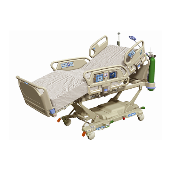
What is the typical length of life for a Progressa mattress
The typical lifespan of a Hill-Rom Progressa Bed mattress is 5 years for the integrated bed surface and 2 years for the removable mattress cover.
This answer is automatically generated
Can the bed be used to safely verticalize the patient? Can the patient bear weight in this position?