Sign In
Upload
Download
Table of Contents
Contents
Add to my manuals
Delete from my manuals
Share
URL of this page:
HTML Link:
Bookmark this page
Add
Manual will be automatically added to "My Manuals"
Print this page
×
Bookmark added
×
Added to my manuals
Manuals
Brands
Hill-Rom Manuals
Medical Equipment
Basic Care Bed
Service manual
Hill-Rom Basic Care Bed Service Manual
Hide thumbs
1
2
3
4
Table Of Contents
5
6
7
8
9
10
11
12
13
14
15
16
17
18
19
20
21
22
23
24
25
26
27
28
29
30
31
32
33
34
35
36
37
38
39
40
41
42
43
44
45
46
47
48
49
50
51
52
53
54
55
56
57
58
59
60
61
62
63
64
65
66
67
68
69
70
71
72
73
74
75
76
77
78
79
80
81
82
83
84
85
86
87
88
89
90
91
92
93
94
95
96
97
98
99
100
101
102
103
104
105
106
107
108
109
110
111
112
113
114
115
116
117
118
119
120
121
122
123
124
125
126
127
128
129
130
131
132
133
134
135
136
137
138
139
140
141
142
143
144
145
146
147
148
149
150
151
152
153
154
155
156
157
158
159
160
161
162
163
164
165
166
167
168
169
170
171
172
173
174
175
176
page
of
176
Go
/
176
Contents
Table of Contents
Troubleshooting
Bookmarks
Table of Contents
Table of Contents
Chapter 1: Introduction
Purpose
Audience
Reference Documents
Document Symbols
Specifications
Physical Description
Electrical Description
Regulations, Standards, and Codes
Model Identification
Safety Tips
Warning and Caution Labels
Chapter 2: Troubleshooting Procedures
Getting Started
Initial Actions
Function Checks
Final Actions
None of the Bed Functions Operate
The Head up Function Does Not Operate
The Head down Function Does Not Operate
The Head Function Does Not Operate
The Knee up Function Does Not Operate
The Knee down Function Does Not Operate
The Knee Function Does Not Operate
The Hilow up Function Does Not Operate
The Hilow down Function Does Not Operate
The Hilow Function Does Not Operate
The Automatic Contour up Function Does Not Operate
The Automatic Contour down Function Does Not Operate
The Trendelenburg or Reverse Trendelenburg Function Does Not Operate
The CPR Function Does Not Operate
Chapter 3: Theory of Operation
Introduction
Base
Intermediate Frame
Articulating Sleep Deck
Siderails
Motion Control
Transformer Configurations
Motor Assemblies
Battery Backup
Controls
Chapter 4: Removal, Replacement, and Adjustment Procedures
Tool and Supply Requirements
Control Box Assembly
Control Panel, Foot End
Trendelenburg Control Box
Trendelenburg or Reverse Trendelenburg Assembly
Trendelenburg and Reverse Trendelenburg Indicators
Fuses
Battery Backup
Head Motor
CPR Cable
Knee Motor
Hilow Motor
Manual Crank Handle Assembly
Head or Knee Crank Rod and Drive Screw Assembly (Manual Model Only)
Hilow Crank Rod and Drive Screw Assembly Including Gas Springs
(Manual Model Only)
CPR Handle Assembly
Siderails
Siderail Slide Bracket
Siderail Retraction Assembly
Siderail Guard Assembly (Foot End)
Siderail Guard Assembly (Head End)
Siderail Control Assembly
Siderail Control Cable
Siderail Top Cane
Siderail Wire Cover
Central Brake and Steer-Caster Assemblies
Central Brake and Steer-Pedal Assemblies
Casters for Individual Brake and Steer
4-Corner Brake and Steer-Caster Assembly
Bumper
Sleep Surface Panels
Chapter 5: Parts List
Service Parts Ordering
Exchange Policy
In-Warranty Exchanges
Out-Of-Warranty Exchanges
Warranty
Recommended Spare Parts
Base Frame-Model a
Upper Frame-P1440-Model a
Upper Frame-P1441-Model a
Siderails-Model a
Power Cord
Sleep Surface
Base Frame-Model B
Upper Frame-P1440-Model B
Siderails-Model B
Chapter 6: General Procedures
Cleaning and Care
General Cleaning
Steam Cleaning
Hard to Clean Spots
Disinfecting
Component Handling
PC Board
Lubrication Requirements
Preventive Maintenance
Preventive Maintenance Schedule
Preventive Maintenance Checklist
Sleep Mode
CPR Cable Adjustment
Chapter 7: Accessories
Accessories
Pole-P1445
Installation
Removal
Adjustment
Trapeze Support-P846F
Installation
Removal
Fracture Frame Adapter-P847B and P847C
Installation
Removal
Advertisement
Quick Links
1
Physical Description
Download this manual
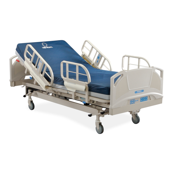
SERVICE MANUAL
Hill-Rom® Basic Care™ Bed,
Hill-Rom® 305 Manual Bed,
Hill-Rom® 405 Electric Bed
From Hill-Rom
Product No. P1440/P1441
MAN336 REV 2
Table of
Contents
Previous
Page
Next
Page
1
2
3
4
5
Advertisement
Table of Contents
Need help?
Do you have a question about the Basic Care Bed and is the answer not in the manual?
Ask a question
Questions and answers
Related Manuals for Hill-Rom Basic Care Bed
Medical Equipment Hill-Rom Centrella Smart+ Product Reference Manual
Bed (30 pages)
Medical Equipment Hill-Rom Compella Bariatric Bed Quick Tips
Advancing bariatric care (21 pages)
Medical Equipment Hill-Rom Compella Troubleshooting Manual
Bariatric bed (2 pages)
Hill-Rom Compella - Bed Tips Manual
(article)
Medical Equipment Hill-Rom Isolette C2000 Service Manual
Infant incubator (93 pages)
Medical Equipment Hill-Rom ISOLETTE C400 QT Service Manual
Infant incubator from hill-rom air-shields (172 pages)
Medical Equipment Hill-Rom CareAssist Service Manual
Bed (379 pages)
Medical Equipment Hill-Rom Basic Care P1440 Service Manual
(160 pages)
Medical Equipment Hill-Rom Excel Care User Manual
Bariatric bed (60 pages)
Medical Equipment Hill-Rom TotalCare Bariatric Bed User Manual
(112 pages)
Medical Equipment Hill-Rom VersaCare Bed User Manual
(96 pages)
Medical Equipment Hill-Rom Resident LTC Bed Manual
(231 pages)
Medical Equipment Hill-Rom Progressa Bed User Manual
(106 pages)
Medical Equipment Hill-Rom CareAssist Bed P1170 User Manual
(54 pages)
Medical Equipment Hill-Rom 305 Manual Bed Service Manual
(176 pages)
Medical Equipment Hill-Rom P1190 User Manual
Advanta 2 bed (62 pages)
This manual is also suitable for:
305 manual bed
405 electric bed
P1440a
P1441a
P1440b
P1441b
Table of Contents
Save PDF
Print
Rename the bookmark
Delete bookmark?
Delete from my manuals?
Login
Sign In
OR
Sign in with Facebook
Sign in with Google
Upload manual
Upload from disk
Upload from URL


Need help?
Do you have a question about the Basic Care Bed and is the answer not in the manual?
Questions and answers