
Related Manuals for Hill-Rom VersaCare P3200


Summary of Contents for Hill-Rom VersaCare P3200
- Page 1 SERVICE MANUAL VersaCare™ From Hill-Rom Product No. P3200/P3201 For Parts or Technical Assistance MAN333 REV 2 USA 800-445-3720 Canada 800-267-2337 International: Contact your distributor.
- Page 3 VersaCare™ Bed Service Manual Revisions Revision Pages Affected Date Original Issue February 2004 January 2005 MAN333 REV 2 VersaCare™ Bed Service Manual (MAN333 REV 2) Page i...
- Page 4 No part of this text shall be reproduced or transmitted in any form or by any means, electronic or mechanical, including photocopying, recording, or by any information or retrieval system without written permission from Hill-Rom Services, Inc. (Hill-Rom). The information in this manual is confidential and may not be disclosed to third parties without the prior written consent of Hill-Rom.
- Page 5 VersaCare™ is a trademark of Hill-Rom Services, Inc. The information contained in this manual is subject to change without notice. Hill-Rom makes no commitment to update or keep current, the information contained in this manual. The only product warranty intended by Hill-Rom is the express, written warranty accompanying the bill of sale to the original purchaser.
- Page 6 Revisions NOTES: Page iv VersaCare™ Bed Service Manual (MAN333 REV 2)
-
Page 7: Table Of Contents
Table of Contents Chapter 1: Introduction Purpose ............1 - 1 Audience . - Page 8 Electronics (Sheet 2 of 2) ......... . . 2 - 14 Logic P.C.
- Page 9 Not Reaching Head Zone Pressure ........2 - 44 Not Reaching Seat Zone Pressure.
- Page 10 Controller Check—IntelliDrive® Transport System ..... . 2 - 75 Visual Inspection—IntelliDrive® Transport System ..... . 2 - 77 Junction Board Debugging—IntelliDrive®...
- Page 11 Mattress............4 - 3 Removal .
- Page 12 Foot Pedal Assembly ..........4 - 32 Removal .
- Page 13 Removal ........... . . 4 - 72 Replacement .
- Page 14 Removal ........... . . 4 - 99 Replacement .
- Page 15 Replacement ..........4 - 134 Chapter 5: Parts List Service Parts Ordering .
- Page 16 Labels (Sheet 1 of 2) ..........5 - 64 Labels (Sheet 2 of 2) .
- Page 17 Installation ........... . 7 - 6 Removal .
- Page 18 NOTES: Page xvi VersaCare™ Bed Service Manual (MAN333 REV 2)
-
Page 19: Chapter 1: Introduction
Chapter 1 Introduction Purpose This manual provides requirements for the VersaCare™ Bed normal operation and maintenance. It also includes parts lists (in chapter 5) for ordering replacement components. Audience This manual is intended for use by only facility-authorized personnel. Failure to observe this restriction can result in severe injury to people and serious damage to equipment. -
Page 20: Chapter 4: Removal, Replacement, And Adjustment Procedures
Organization Chapter 1: Introduction Chapter 4: Removal, Replacement, and Adjustment Procedures Chapter 4 contains the detailed maintenance procedures determined necessary in chapter 2. Chapter 5: Parts List This chapter contains the warranty, part-ordering procedure, and illustrated parts lists. Chapter 6: General Procedures Cleaning, preventive maintenance, and other general procedures are described in this chapter. -
Page 21: Document Symbol Definition
Document Symbol Definition Chapter 1: Introduction Document Symbol Definition This manual contains different typefaces and icons designed to improve readability and increase understanding of its content. Note the following examples: • Standard text—used for regular information. • Boldface text—emphasizes a word or phrase. • NOTE:—sets apart special information or important instruction clarification. -
Page 22: Overview
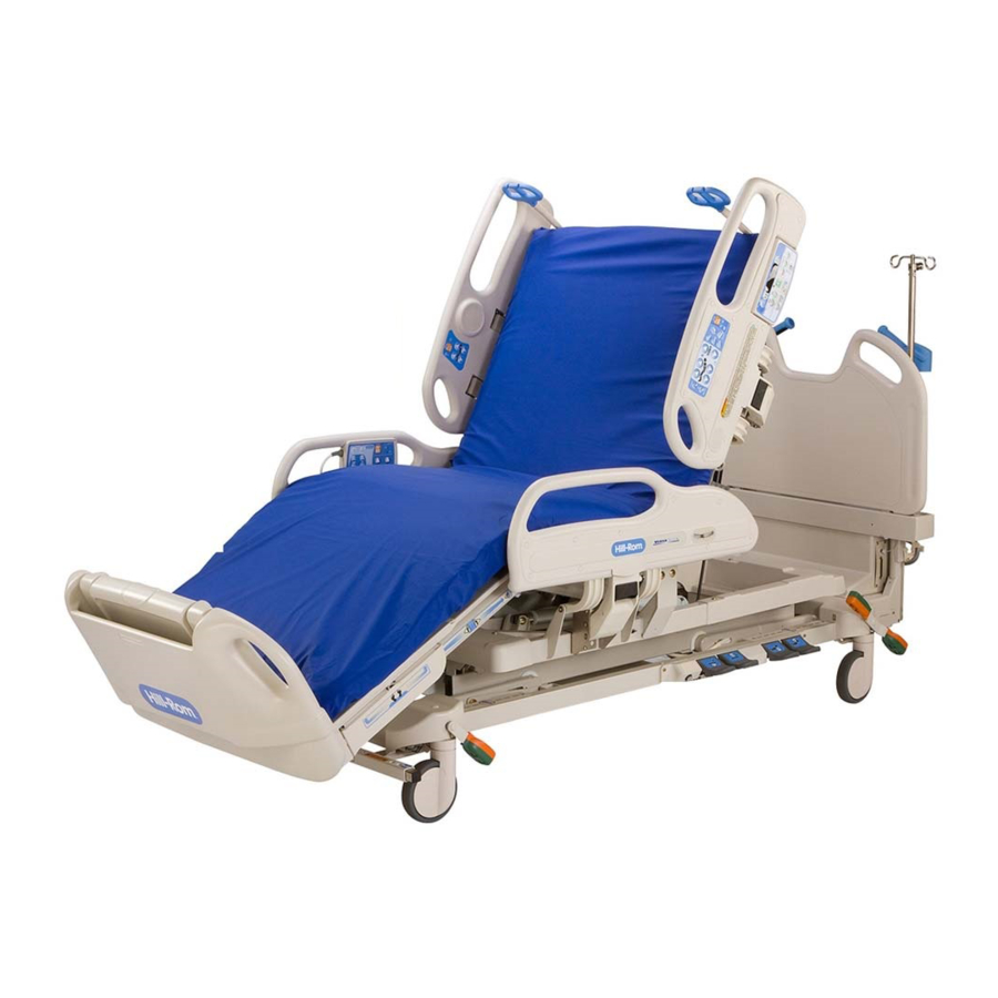
Overview Chapter 1: Introduction Overview The VersaCare™ Bed is intended for low to moderate acuity patients in the medical/surgical area of the hospital. The VersaCare™ Bed can also be used as a general-purpose variable height hospital bed for general care, post-operative care, and general medicine wards. -
Page 23: Specifications
Specifications Chapter 1: Introduction Specifications For VersaCare™ Bed specifications, see table 1-1 on page 1-5. Table 1-1. Specifications Feature Dimension Total Length: Foot Section Extended 94.5" (240.0 cm) Foot Section Retracted 82.5" (210.0 cm) Maximum Width (siderails stored) 37" (94 cm) Maximum Width (siderails up) 40"... - Page 24 Specifications Chapter 1: Introduction Feature Dimension Bed Height Range, Lowest Position (with 18" (46 cm) without IntelliDrive® Trans- mattress) port System 22" (56 cm) with IntelliDrive® Transport System Bed Height Range, Highest Position (with 37" (94 cm) without IntelliDrive® Trans- mattress) port System 38"...
-
Page 25: Electrical Description
Specifications Chapter 1: Introduction Electrical Description AC Power Requirements Nominal Power Nominal Power Maximum Equipment Distribution Voltage Distribution Frequency Current (Amps) (Volts) (Hertz) 120 (P3200) 100/110/115/120/127 50/60 (P3201) 220/230/240 (P3201) 50/60 a. North American power supply configuration. Fuse Specifications Condition Range Battery fuse 250 V, 15 A fast blow, 3AB... - Page 26 Specifications Chapter 1: Introduction Equipment Classification per IEC 60601-1 Type B Degree of Protection Against Electric Class I equipment, internally powered Shock equipment Classification according to Directive Class I, Class IIa for treatment 93/42/EEC Degree of Protection Against Ingress of IPX4 Water Degree of Protection Against the Presence...
- Page 27 Specifications Chapter 1: Introduction European Mattress Flammability Codes Condition Range BS 7177: 1996, Specification for Resistance to Ignition P3251A and P3250EA of Mattresses, Divans and Bed Bases (Surfaces Only) BS 5852: 1990, Assessment of Ignitability of Uphol stered Seating by Smouldering and Flaming Ignition Sources (Surfaces and Siderail Coverings Only) BS EN 597-1: 1995, Furniture - Assessment of the Ignitability of Mattresses and Upholstered Bed Bases;...
- Page 28 Specifications Chapter 1: Introduction Electromagnetic Immunity Guidance Guidance and Manufacturer's Declaration - Electromagnetic Emissions The VersaCare™ Bed model P3200/P3201 is intended for use in the electromagnetic environment specified below. The customer or the user of the model P3200/P3201 should make sure it is used in such an environment. IEC 60601 Electromagnetic Immunity Test...
-
Page 29: Model Identification
Specifications Chapter 1: Introduction Guidance and Manufacturer's Declaration - Electromagnetic Emissions The VersaCare™ Bed model P3200/P3201 is intended for use in the electromagnetic environment specified below. The customer or the user of the model P3200/P3201 should make sure it is used in such an environment. IEC 60601 Electromagnetic Immunity Test... -
Page 30: Safety Tips
Safety Tips Chapter 1: Introduction Safety Tips WARNING: Only facility-authorized personnel should service the VersaCare™ Bed. Servicing by unauthorized personnel could result in personal injury or equipment damage. WARNING: Adhere to appropriate infection control policies. Failure to do so could result in the spread of infection. - Page 31 Safety Tips Chapter 1: Introduction SHOCK HAZARD: Unplug the bed from its power source. Failure to do so could result in personal injury or equipment damage. SHOCK HAZARD: Do not expose the bed to excessive moisture. Personal injury or equipment damage could occur. SHOCK HAZARD: High voltage is present.
- Page 32 Safety Tips Chapter 1: Introduction CAUTION: Make sure the vent holes are clear. Failure to do so could result in overheating and equipment damage. CAUTION: Use care when disconnecting the hose from the fitting. Excessive force can damage the fitting. Page 1 - 14 VersaCare™...
-
Page 33: Warning And Caution Labels
Warning and Caution Labels Chapter 1: Introduction Warning and Caution Labels 7082501 Siderail Warning 7082502 Siderail Warning with Scale operation instructions 66870 Battery Warning 128815 IV Pole Warning 127866 Foot Warning VersaCare™ Bed Service Manual (MAN333 REV 2) Page 1 - 15... - Page 34 Warning and Caution Labels Chapter 1: Introduction NOTES: Page 1 - 16 VersaCare™ Bed Service Manual (MAN333 REV 2)
-
Page 35: Chapter 2: Troubleshooting Procedures
Function Checks. To verify the repair, perform the Final Actions after the Function Checks. If troubleshooting procedures do not isolate the problem, call Hill-Rom Technical Support at (800) 445-3720 for assistance. VersaCare™ Bed Service Manual (MAN333 REV 2) -
Page 36: Initial Actions
Initial Actions Chapter 2: Troubleshooting Procedures Initial Actions Use Initial Actions to gather information from operators concerning problems with the VersaCare™ Bed. Note the symptoms or other information concerning the problem that the operator describes. This information helps identify the probable cause. 1. -
Page 37: Rapid Problem/Solution Identification Tables
Initial Actions Chapter 2: Troubleshooting Procedures Rapid Problem/Solution Identification Tables If the Service Required indicator is flashing or solid, use the following table to identify the appropriate troubleshooting procedure (see table 2-1 on page 2-3). Table 2-1. Flashing or Solid Service Required LED Long Short Description... - Page 38 Initial Actions Chapter 2: Troubleshooting Procedures If the scale/PPM display is showing an error or will not arm, use the following table to identify the appropriate troubleshooting procedure (see table 2-2 on page 2-4). Table 2-2. Scale/PPM Display Errors Error Solution Err0 Go to RAP 2.37 on page 2-49.
- Page 39 Initial Actions Chapter 2: Troubleshooting Procedures For IntelliDrive® Transport System errors, use the following table to identify the appropriate troubleshooting procedure (see table 2-4 on page 2-5). Table 2-4. IntelliDrive® Transport System Error Solution Bed Will Not Drive Go to RAP 2.48 on page 2-60. Bed Will Not Drive, Wheel Is Down Go to RAP 2.49 on page 2-61.
-
Page 40: Function Checks
Function Checks Chapter 2: Troubleshooting Procedures Function Checks 1. The "Initial Actions" have been performed. ↓ → Go to “Initial Actions” on page 2-2. 2. Operate the trendelenburg function. This function works. ↓ → Go to RAP 2.1 on page 2-13 or go to RAP 2.16 on page 2-28. 3. Lock out the head, knee, hilow, and Master controls. - Page 41 Function Checks Chapter 2: Troubleshooting Procedures The knee section goes down to the low position without stopping. ↓ → Go to RAP 2.1 on page 2-13 or go to RAP 2.16 on page 2-28. 9. Press the Head Up control of the head section function. The head section rises to the high position without stopping.
- Page 42 Function Checks Chapter 2: Troubleshooting Procedures 15. Press the Foot Retraction control. The foot section retracts to the full in position without stopping. ↓ → Go to RAP 2.1 on page 2-13 or go to RAP 2.16 on page 2-28. 16.
- Page 43 Function Checks Chapter 2: Troubleshooting Procedures ↓ → Go to RAP 2.1 on page 2-13 or go to RAP 2.16 on page 2-28. 21. Continue to hold the CPR handle. The bed continues into the Trendelenburg position. ↓ → Go to RAP 2.1 on page 2-13 or go to RAP 2.16 on page 2-28. 22.
-
Page 44: Treatment Surface Function Check
Function Checks Chapter 2: Troubleshooting Procedures Treatment Surface Function Check 1. Press the Max-inflate control on the intermediate siderail. After 30 seconds, wipe your hand across the mattress. Verify that the three zones are inflated to a high pressure. ↓ →... - Page 45 Function Checks Chapter 2: Troubleshooting Procedures The Right Turn Assist bladder inflates and an alarm sounds when one of the right side siderails is lowered. ↓ → Go to RAP 2.24. 8. Place all four siderails in the up and locked position. Activate the Left Turn Assist control.
-
Page 46: Final Actions
Final Actions Chapter 2: Troubleshooting Procedures Final Actions 1. Do the required preventative maintenance procedures. See “Preventive Maintenance” on page 6-4. 2. Do all required administrative tasks. Page 2 - 12 VersaCare™ Bed Service Manual (MAN333 REV 2) -
Page 47: Electronics (Sheet 1 Of 2)
2.1 Electronics (Sheet 1 of 2) Chapter 2: Troubleshooting Procedures Electronics (Sheet 1 of 2) VersaCare™ Bed Service Manual (MAN333 REV 2) Page 2 - 13... -
Page 48: Electronics (Sheet 2 Of 2)
2.2 Electronics (Sheet 2 of 2) Chapter 2: Troubleshooting Procedures Electronics (Sheet 2 of 2) Page 2 - 14 VersaCare™ Bed Service Manual (MAN333 REV 2) -
Page 49: Logic P.c. Board Diagnostic Led Codes
2.3 Logic P.C. Board Diagnostic LED Codes Chapter 2: Troubleshooting Procedures Logic P.C. Board Diagnostic LED Codes Table 2-5. Logic P.C. Board Diagnostic LED Codes Green Amber Error Solution Bootloader Go to RAP 2.4. Supervisory Relay Error Flash Go to RAP 2.4. EEPROM Failure Go to RAP 2.4. -
Page 50: Bootloader, Supervisory Relay Error, Eeprom Failure, And All Lockout Led Error
2.4 Bootloader, Supervisory Relay Error, EEPROM Failure, and All Lockout LED Error Chapter 2: Troubleshooting Procedures 2.4 Bootloader, Supervisory Relay Error, EEPROM Failure, and All Lockout LED Error Page 2 - 16 VersaCare™ Bed Service Manual (MAN333 REV 2) -
Page 51: Head, Knee, Hilow Lockout Led Error And Cpr Switch Failure
2.5 Head, Knee, Hilow Lockout LED Error and CPR Switch Failure Chapter 2: Troubleshooting Procedures Head, Knee, Hilow Lockout LED Error and CPR Switch Failure VersaCare™ Bed Service Manual (MAN333 REV 2) Page 2 - 17... -
Page 52: Hilow Motor Unexpected Motion
2.6 Hilow Motor Unexpected Motion Chapter 2: Troubleshooting Procedures Hilow Motor Unexpected Motion Page 2 - 18 VersaCare™ Bed Service Manual (MAN333 REV 2) -
Page 53: Head, Knee, Leg, And Foot Motor Unexpected Motion
2.7 Head, Knee, Leg, and Foot Motor Unexpected Motion Chapter 2: Troubleshooting Procedures Head, Knee, Leg, and Foot Motor Unexpected Motion VersaCare™ Bed Service Manual (MAN333 REV 2) Page 2 - 19... -
Page 54: Motor Overcurrent
2.8 Motor Overcurrent Chapter 2: Troubleshooting Procedures Motor Overcurrent Page 2 - 20 VersaCare™ Bed Service Manual (MAN333 REV 2) -
Page 55: Hilow Motor Position Rate High
2.9 Hilow Motor Position Rate High Chapter 2: Troubleshooting Procedures Hilow Motor Position Rate High VersaCare™ Bed Service Manual (MAN333 REV 2) Page 2 - 21... -
Page 56: Hilow Motor Position Rate Low
2.10 Hilow Motor Position Rate Low Chapter 2: Troubleshooting Procedures 2.10 Hilow Motor Position Rate Low Page 2 - 22 VersaCare™ Bed Service Manual (MAN333 REV 2) -
Page 57: Absolute Minimum Drive Current Failure
2.11 Absolute Minimum Drive Current Failure Chapter 2: Troubleshooting Procedures 2.11 Absolute Minimum Drive Current Failure VersaCare™ Bed Service Manual (MAN333 REV 2) Page 2 - 23... -
Page 58: Network Heartbeat Failure System Level
2.12 Network Heartbeat Failure System Level Chapter 2: Troubleshooting Procedures 2.12 Network Heartbeat Failure System Level Page 2 - 24 VersaCare™ Bed Service Manual (MAN333 REV 2) -
Page 59: Patient Pendant Causing Logic P.c. Board Failure
2.13 Patient Pendant Causing Logic P.C. Board Failure Chapter 2: Troubleshooting Procedures 2.13 Patient Pendant Causing Logic P.C. Board Failure VersaCare™ Bed Service Manual (MAN333 REV 2) Page 2 - 25... -
Page 60: Logic Circuit Failure
2.14 Logic Circuit Failure Chapter 2: Troubleshooting Procedures 2.14 Logic Circuit Failure Page 2 - 26 VersaCare™ Bed Service Manual (MAN333 REV 2) -
Page 61: Nuisance Trip
2.15 Nuisance Trip Chapter 2: Troubleshooting Procedures 2.15 Nuisance Trip VersaCare™ Bed Service Manual (MAN333 REV 2) Page 2 - 27... -
Page 62: Motors Do Not Operate
2.16 Motors Do Not Operate Chapter 2: Troubleshooting Procedures 2.16 Motors Do Not Operate Page 2 - 28 VersaCare™ Bed Service Manual (MAN333 REV 2) -
Page 63: No Ac Power
2.17 No AC Power Chapter 2: Troubleshooting Procedures 2.17 No AC Power VersaCare™ Bed Service Manual (MAN333 REV 2) Page 2 - 29... -
Page 64: Ac Power, No Motor Power
2.18 AC Power, No Motor Power Chapter 2: Troubleshooting Procedures 2.18 AC Power, No Motor Power Page 2 - 30 VersaCare™ Bed Service Manual (MAN333 REV 2) -
Page 65: No Dc Power
2.19 No DC Power Chapter 2: Troubleshooting Procedures 2.19 No DC Power VersaCare™ Bed Service Manual (MAN333 REV 2) Page 2 - 31... -
Page 66: Power Supply Error Codes
2.20 Power Supply Error Codes Chapter 2: Troubleshooting Procedures 2.20 Power Supply Error Codes Page 2 - 32 VersaCare™ Bed Service Manual (MAN333 REV 2) -
Page 67: Siderail Controls Not Working
2.21 Siderail Controls Not Working Chapter 2: Troubleshooting Procedures 2.21 Siderail Controls Not Working VersaCare™ Bed Service Manual (MAN333 REV 2) Page 2 - 33... -
Page 68: Siderail Detection Switch Without Sidecom® Communication System
2.22 Siderail Detection Switch Without SideCom® Communication System Chapter 2: Troubleshooting Procedures 2.22 Siderail Detection Switch Without SideCom® Communication System Page 2 - 34 VersaCare™ Bed Service Manual (MAN333 REV 2) -
Page 69: Siderail Detection Switch With Sidecom® Communication System
2.23 Siderail Detection Switch With SideCom® Communication System Chapter 2: Troubleshooting Procedures 2.23 Siderail Detection Switch With SideCom® Communication System VersaCare™ Bed Service Manual (MAN333 REV 2) Page 2 - 35... -
Page 70: Air Surface (Sheet 1 Of 2)
2.24 Air Surface (Sheet 1 of 2) Chapter 2: Troubleshooting Procedures 2.24 Air Surface (Sheet 1 of 2) Page 2 - 36 VersaCare™ Bed Service Manual (MAN333 REV 2) -
Page 71: Air Surface (Sheet 2 Of 2)
2.25 Air Surface (Sheet 2 of 2) Chapter 2: Troubleshooting Procedures 2.25 Air Surface (Sheet 2 of 2) VersaCare™ Bed Service Manual (MAN333 REV 2) Page 2 - 37... -
Page 72: System Error, No Flash Code
2.26 System Error, No Flash Code Chapter 2: Troubleshooting Procedures 2.26 System Error, No Flash Code Page 2 - 38 VersaCare™ Bed Service Manual (MAN333 REV 2) -
Page 73: Mattress Disconnected
2.27 Mattress Disconnected Chapter 2: Troubleshooting Procedures 2.27 Mattress Disconnected VersaCare™ Bed Service Manual (MAN333 REV 2) Page 2 - 39... -
Page 74: Head Angle Sensor Error
2.28 Head Angle Sensor Error Chapter 2: Troubleshooting Procedures 2.28 Head Angle Sensor Error Page 2 - 40 VersaCare™ Bed Service Manual (MAN333 REV 2) -
Page 75: Head Fsr1 And Fsr2
2.29 Head FSR1 and FSR2 Chapter 2: Troubleshooting Procedures 2.29 Head FSR1 and FSR2 VersaCare™ Bed Service Manual (MAN333 REV 2) Page 2 - 41... -
Page 76: Accumulator Pressure
2.30 Accumulator Pressure Chapter 2: Troubleshooting Procedures 2.30 Accumulator Pressure Page 2 - 42 VersaCare™ Bed Service Manual (MAN333 REV 2) -
Page 77: Missing 24 V Dc Input
2.31 Missing 24 V DC Input Chapter 2: Troubleshooting Procedures 2.31 Missing 24 V DC Input VersaCare™ Bed Service Manual (MAN333 REV 2) Page 2 - 43... -
Page 78: Not Reaching Head Zone Pressure
2.32 Not Reaching Head Zone Pressure Chapter 2: Troubleshooting Procedures 2.32 Not Reaching Head Zone Pressure Page 2 - 44 VersaCare™ Bed Service Manual (MAN333 REV 2) -
Page 79: Not Reaching Seat Zone Pressure
2.33 Not Reaching Seat Zone Pressure Chapter 2: Troubleshooting Procedures 2.33 Not Reaching Seat Zone Pressure VersaCare™ Bed Service Manual (MAN333 REV 2) Page 2 - 45... -
Page 80: Not Reaching Foot Zone Pressure
2.34 Not Reaching Foot Zone Pressure Chapter 2: Troubleshooting Procedures 2.34 Not Reaching Foot Zone Pressure Page 2 - 46 VersaCare™ Bed Service Manual (MAN333 REV 2) -
Page 81: Not Reaching Right Turn Assist Pressure
2.35 Not Reaching Right Turn Assist Pressure Chapter 2: Troubleshooting Procedures 2.35 Not Reaching Right Turn Assist Pressure VersaCare™ Bed Service Manual (MAN333 REV 2) Page 2 - 47... -
Page 82: Not Reaching Left Turn Assist Pressure
2.36 Not Reaching Left Turn Assist Pressure Chapter 2: Troubleshooting Procedures 2.36 Not Reaching Left Turn Assist Pressure Page 2 - 48 VersaCare™ Bed Service Manual (MAN333 REV 2) -
Page 83: Scale Error 0
2.37 Scale Error 0 Chapter 2: Troubleshooting Procedures 2.37 Scale Error 0 VersaCare™ Bed Service Manual (MAN333 REV 2) Page 2 - 49... -
Page 84: Scale Error 1
2.38 Scale Error 1 Chapter 2: Troubleshooting Procedures 2.38 Scale Error 1 Page 2 - 50 VersaCare™ Bed Service Manual (MAN333 REV 2) -
Page 85: Scale Error 2
2.39 Scale Error 2 Chapter 2: Troubleshooting Procedures 2.39 Scale Error 2 VersaCare™ Bed Service Manual (MAN333 REV 2) Page 2 - 51... -
Page 86: Scale Error 3
2.40 Scale Error 3 Chapter 2: Troubleshooting Procedures 2.40 Scale Error 3 Page 2 - 52 VersaCare™ Bed Service Manual (MAN333 REV 2) -
Page 87: Scale Error 4 And 5 (European Scale Only)
2.41 Scale Error 4 and 5 (European Scale Only) Chapter 2: Troubleshooting Procedures 2.41 Scale Error 4 and 5 (European Scale Only) VersaCare™ Bed Service Manual (MAN333 REV 2) Page 2 - 53... -
Page 88: Sidecom® Communication System
2.42 SideCom® Communication System Chapter 2: Troubleshooting Procedures 2.42 SideCom® Communication System Page 2 - 54 VersaCare™ Bed Service Manual (MAN333 REV 2) -
Page 89: Patient Position Monitor System With Scale Display
2.43 Patient Position Monitor System with Scale Display Chapter 2: Troubleshooting Procedures 2.43 Patient Position Monitor System with Scale Display VersaCare™ Bed Service Manual (MAN333 REV 2) Page 2 - 55... -
Page 90: Patient Position Monitor Without Scale Display
2.44 Patient Position Monitor without Scale Display Chapter 2: Troubleshooting Procedures 2.44 Patient Position Monitor without Scale Display Page 2 - 56 VersaCare™ Bed Service Manual (MAN333 REV 2) -
Page 91: Crc Error
2.45 CRC Error Chapter 2: Troubleshooting Procedures 2.45 CRC Error VersaCare™ Bed Service Manual (MAN333 REV 2) Page 2 - 57... -
Page 92: Patient Pendant
2.46 Patient Pendant Chapter 2: Troubleshooting Procedures 2.46 Patient Pendant Page 2 - 58 VersaCare™ Bed Service Manual (MAN333 REV 2) -
Page 93: Obstacle Detection
2.47 Obstacle Detection Chapter 2: Troubleshooting Procedures 2.47 Obstacle Detection VersaCare™ Bed Service Manual (MAN333 REV 2) Page 2 - 59... -
Page 94: Bed Will Not Drive (Intellidrive® Transport System)
2.48 Bed Will Not Drive (IntelliDrive® Transport System) Chapter 2: Troubleshooting Procedures 2.48 Bed Will Not Drive (IntelliDrive® Transport System) Page 2 - 60 VersaCare™ Bed Service Manual (MAN333 REV 2) -
Page 95: Bed Will Not Drive, Wheel Is Down (Intellidrive® Transport System)
2.49 Bed Will Not Drive, Wheel Is Down (IntelliDrive® Transport System) Chapter 2: Troubleshooting Procedures 2.49 Bed Will Not Drive, Wheel Is Down (IntelliDrive® Transport System) VersaCare™ Bed Service Manual (MAN333 REV 2) Page 2 - 61... -
Page 96: Wheel Will Not Stow (Intellidrive® Transport System)
2.50 Wheel Will Not Stow (IntelliDrive® Transport System) Chapter 2: Troubleshooting Procedures 2.50 Wheel Will Not Stow (IntelliDrive® Transport System) Page 2 - 62 VersaCare™ Bed Service Manual (MAN333 REV 2) -
Page 97: Battery Check (Intellidrive® Transport System)
2.51 Battery Check (IntelliDrive® Transport System) Chapter 2: Troubleshooting Procedures 2.51 Battery Check (IntelliDrive® Transport System) VersaCare™ Bed Service Manual (MAN333 REV 2) Page 2 - 63... -
Page 98: Steer Switch Check (Intellidrive® Transport System)
2.52 Steer Switch Check (IntelliDrive® Transport System) Chapter 2: Troubleshooting Procedures 2.52 Steer Switch Check (IntelliDrive® Transport System) Page 2 - 64 VersaCare™ Bed Service Manual (MAN333 REV 2) -
Page 99: Pacm Board Power Check (Intellidrive® Transport System)
2.53 PACM Board Power Check (IntelliDrive® Transport System) Chapter 2: Troubleshooting Procedures 2.53 PACM Board Power Check (IntelliDrive® Transport System) VersaCare™ Bed Service Manual (MAN333 REV 2) Page 2 - 65... -
Page 100: Pacm Board Deployment Check (Intellidrive® Transport System)
2.54 PACM Board Deployment Check (IntelliDrive® Transport System) Chapter 2: Troubleshooting Procedures 2.54 PACM Board Deployment Check (IntelliDrive® Transport System) Page 2 - 66 VersaCare™ Bed Service Manual (MAN333 REV 2) -
Page 101: Pacm Board Drive Check (Intellidrive® Transport System)
2.55 PACM Board Drive Check (IntelliDrive® Transport System) Chapter 2: Troubleshooting Procedures 2.55 PACM Board Drive Check (IntelliDrive® Transport System) VersaCare™ Bed Service Manual (MAN333 REV 2) Page 2 - 67... -
Page 102: Motor Check (Intellidrive® Transport System)
2.56 Motor Check (IntelliDrive® Transport System) Chapter 2: Troubleshooting Procedures 2.56 Motor Check (IntelliDrive® Transport System) Page 2 - 68 VersaCare™ Bed Service Manual (MAN333 REV 2) -
Page 103: Pacm To Junction Board Cable Check (Intellidrive® Transport System)
2.57 PACM to Junction Board Cable Check (IntelliDrive® Transport System) Chapter 2: Troubleshooting Procedures 2.57 PACM to Junction Board Cable Check (IntelliDrive® Transport System) VersaCare™ Bed Service Manual (MAN333 REV 2) Page 2 - 69... -
Page 104: Handle Enable Switch Check (Intellidrive® Transport System)
2.58 Handle Enable Switch Check (IntelliDrive® Transport System) Chapter 2: Troubleshooting Procedures 2.58 Handle Enable Switch Check (IntelliDrive® Transport System) Page 2 - 70 VersaCare™ Bed Service Manual (MAN333 REV 2) -
Page 105: Throttle Check (Intellidrive® Transport System)
2.59 Throttle Check (IntelliDrive® Transport System) Chapter 2: Troubleshooting Procedures 2.59 Throttle Check (IntelliDrive® Transport System) VersaCare™ Bed Service Manual (MAN333 REV 2) Page 2 - 71... -
Page 106: Handle Gauge Check (Intellidrive® Transport System) (Sheet 1 Of 3)
2.60 Handle Gauge Check (IntelliDrive® Transport System) (Sheet 1 of 3) Chapter 2: Troubleshooting Procedures 2.60 Handle Gauge Check (IntelliDrive® Transport System) (Sheet 1 of 3) Page 2 - 72 VersaCare™ Bed Service Manual (MAN333 REV 2) -
Page 107: Handle Gauge Check (Intellidrive® Transport System) (Sheet 2 Of 3)
2.61 Handle Gauge Check (IntelliDrive® Transport System) (Sheet 2 of 3) Chapter 2: Troubleshooting Procedures 2.61 Handle Gauge Check (IntelliDrive® Transport System) (Sheet 2 of 3) VersaCare™ Bed Service Manual (MAN333 REV 2) Page 2 - 73... -
Page 108: Handle Gauge Check (Intellidrive® Transport System) (Sheet 3 Of 3)
2.62 Handle Gauge Check (IntelliDrive® Transport System) (Sheet 3 of 3) Chapter 2: Troubleshooting Procedures 2.62 Handle Gauge Check (IntelliDrive® Transport System) (Sheet 3 of 3) Page 2 - 74 VersaCare™ Bed Service Manual (MAN333 REV 2) -
Page 109: Controller Check-Intellidrive® Transport System
2.63 Controller Check—IntelliDrive® Transport System Chapter 2: Troubleshooting Procedures 2.63 Controller Check—IntelliDrive® Transport System 1. Remove the drive box from the bed. 2. Place the drive box on wooden supports so the drive belt will not touch the ground when it deploys. 3. - Page 110 2.63 Controller Check—IntelliDrive® Transport System Chapter 2: Troubleshooting Procedures Flash Code Description Possible Cause ¤ ¤¤¤¤¤ Overvoltage 1) Make sure the controller is getting correct bat tery voltage. 2) Replace Controller. ¤¤ ¤ Main OFF Fault 1) Check motor wiring. 2) Make sure the controller is getting correct bat...
-
Page 111: Visual Inspection-Intellidrive® Transport System
2.64 Visual Inspection—IntelliDrive® Transport System Chapter 2: Troubleshooting Procedures 2.64 Visual Inspection—IntelliDrive® Transport System Tools required: Flashlight Inspection mirror 1. Check the unit for external damage. 2. Using the mirror and flashlight, check for debris around the pulleys and levers. 3. -
Page 112: Junction Board Debugging-Intellidrive® Transport System
2.65 Junction Board Debugging—IntelliDrive® Transport System Chapter 2: Troubleshooting Procedures 2.65 Junction Board Debugging—IntelliDrive® Transport System NOTE: When working on IntelliDrive® Transport System use extreme caution when servicing the product. Whenever you are measuring voltages or making adjustments to the Junction board, it is suggested that you take the bed out of steer which will raise the wheel and prevent the bed from moving. - Page 113 2.65 Junction Board Debugging—IntelliDrive® Transport System Chapter 2: Troubleshooting Procedures connector pins at P6 on the Junction board. Also, check connectors P2 and P5 where the enable switches plug into the Junction board. The combined enable switch signal connects to the PACM board via the Junction-PACM board cable.
- Page 114 2.65 Junction Board Debugging—IntelliDrive® Transport System Chapter 2: Troubleshooting Procedures If the output voltage at P1.1 cannot be adjusted to within 2.4V to 2.6V using the potentiometer R1, with no force applied to the handles, the strain element may be damaged. The bed will operate with a single handle after the output is adjusted.
-
Page 115: Chapter 3: Theory Of Operation
Chapter 3 Theory of Operation Introduction There are three Theories of Operation for the VersaCare™ Bed: • Mechanical • Electrical • Pneumatic The interaction between these subsystems lets all the operational functions be used. Each of the subsystems is described separately in the following sections. The schematic diagrams are located at the end of this chapter. -
Page 116: Hilow Lift Module
Mechanical System Chapter 3: Theory of Operation is not part of the weighed components on a scale bed. For this reason, contact between a patient, bedding, etc. and the headboard will affect scale readings. Hilow Lift Module The high low lift module consists of two lift arms, high low DC drives, and intermediate frame. -
Page 117: End Panel Module
Mechanical System Chapter 3: Theory of Operation End Panel Module The end panel module consists of a head panel and a foot panel. The head panel is a flat stationary panel vertically affixed to the base frame near the head end. -
Page 118: Electrical System
Electrical System Chapter 3: Theory of Operation Electrical System Logic and Motor Control Power is supplied to the Logic Control by the P3200 linear power supply. The power supply provides an unregulated 19 - 35 V DC reference to signal GND at 2.5 A max, 1.75 A typical (see Power Supply Node HDD for input supply capabilities). -
Page 119: Power Supply
Electrical System Chapter 3: Theory of Operation The Controller Area Network (CAN) is a common Small Area Network solution that supports distributed product and distributed system architectures. The CAN bus is used to interconnect a network of electronic nodes or modules. Typically, a two wire, twisted pair cable is used for the network interconnection. - Page 120 Electrical System Chapter 3: Theory of Operation air solenoid power, and AC air pump power. Secondary 1 fuse is a 20 A, 250 V, TD, UL. Secondary 1 has a 25% duty cycle. Secondary 2 provides battery charge power, logic power, IntelliDrive® Transport System charge power. Secondary 2 is rated at 28 Vrms @ 6.5 Arms with <...
- Page 121 Electrical System Chapter 3: Theory of Operation IntelliDrive® Transport System Charge Power Connector, P5, provides the 1.1 ADC path to the IntelliDrive® Transport System switching regulator board. P5-4 provides feedback to the microprocessor that the IntelliDrive® Transport System cable is connected. Logic Power P2-6 provides 1.5Adc, 20 to 45 VDC power the logic board depending on whether the system is power by AC or DC.
-
Page 122: User Interface
Electrical System Chapter 3: Theory of Operation AC Detection The circuitry around Q8 detects the presence or absence of AC power and produces a static binary signal. Miscellaneous Drivers Q7 drives the charge supervisory relay, K3. Q11 drives the logic relay, K2. Half of U14 drives the motor power relay, K1. -
Page 123: Patient Pendant
Electrical System Chapter 3: Theory of Operation All of the caregiver control functions revolve around the microcontroller on the standard caregiver control board. This is an 8051 variant with internal 32K flash program, 256 + 1.2K EEPROM data memory, and 8 channels of A/D. External to the microcontroller are the CAN transceiver, watch dog reset circuit, serial I/O devices, and analog mux for interface to the microcontroller's A/D converter. -
Page 124: Sidecom® Communication System
Electrical System Chapter 3: Theory of Operation SPI_IN is the data line for writing to the pendant, which is on pin 7 of the P1 connector. Commands that will be written to the pendant are nurse call and nurse answer. SPI_OUT located on pin 8 of the P1 connector is the serial data being read from the pendant. - Page 125 Electrical System Chapter 3: Theory of Operation The raw digital information is translated and further filtered in software before being placed on the network. If needed, the accelerometer or motor position can be used to detect the level of the bed with respect to the floor and then correct for the cosine error.
-
Page 126: Intellidrive® Transport System
Electrical System Chapter 3: Theory of Operation If the AC power is removed from the bed and the PPM system is armed a priority and Nurse call are placed as well as a local alarm. If for any reason the scale node goes away or cannot communicate the SideCom®... - Page 127 Electrical System Chapter 3: Theory of Operation power components of the circuit board and secondarily provides for mounting the assembly inside the box. The PACM supplies the following functions: • Battery charger • Battery gas gauge • Deployment control • Enable switch logic & relay •...
- Page 128 Electrical System Chapter 3: Theory of Operation Deployment Control There are three inputs to the deployment control circuitry: DC power from the bed, the steer switch, and the enable switch. Also, the deployment motor must provide limit switch output to reflect the extended (deployed or down) and retracted (stowed or up) positions of the deployment motor.
- Page 129 Electrical System Chapter 3: Theory of Operation more than a minute or so, self-resetting fuses (PTCs) interrupt the power connection to the motor controller. As with the switch opening, the motor controller will bring the drive motor to a stop. To manually push the bed in either of these circumstances, the drive wheel can be stowed or the manual override switch can disconnect the motor from the short to release the brake.
-
Page 130: Pneumatic
Electrical System Chapter 3: Theory of Operation remaining charge in the battery, each successive LED representing approximately 20 percent of the battery capacity. The battery capacity indicator also includes a shutdown switch to signal the PACM logic to disconnect the battery. Pneumatic The air system contains the following components: air mattress, pneumatic system, control board, scale system, left and right force sensing resistors, and... -
Page 131: Schematics
Schematics Chapter 3: Theory of Operation Schematics Schematic—Electronics Figure 3-1. Electronics Refer to fold-out FO 3-1 at the rear of this manual. Schematic—Motor Control P.C. Board (PN 68717) Figure 3-2. Motor Control P.C. Board (PN 68717) Refer to fold-out FO 3-2 at the rear of this manual. Schematic—Logic Control P.C. - Page 132 Schematics Chapter 3: Theory of Operation Schematic—Patient Pendant Figure 3-7. Patient Pendant Refer to fold-out FO 3-7 at the rear of this manual. Schematic—Power Supply (PN 72289) Figure 3-8. Power Supply (PN 72289) Refer to fold-out FO 3-8 at the rear of this manual. Schematic—Motor Control P.C.
-
Page 133: Chapter 4: Removal, Replacement, And Adjustment Procedures
Chapter 4 Removal, Replacement, and Adjustment Procedures Tool and Supply Requirements To service the VersaCare™ Bed, the following tools and supplies are required: • Ratchet • Extension, 6" • 7 mm wrench • 13 mm wrench • 13 mm socket •... - Page 134 Tool and Supply Requirements Chapter 4: Removal, Replacement, and Adjustment Procedures • 7/64" drill bit • Drill • #6-32 tap • 3/8" nut driver • Wire cutters • 2" x 4" x 36" piece of wood • String, 10' (305 cm) •...
-
Page 135: Mattress
4.1 Mattress Chapter 4: Removal, Replacement, and Adjustment Procedures Mattress Tools required: Screwdriver Removal 1. Set the brakes. 2. Raise the bed to the high position. 3. Press the Enable control on the siderail controls. 4. Simultaneously press both the Max-Inflate and Pressure Relief controls until both indicators go off. -
Page 136: Replacement
4.1 Mattress Chapter 4: Removal, Replacement, and Adjustment Procedures NOTE: The foot end and head end retaining straps are removed the same way. 8. Remove the other side of the mattress retaining strap from the retainer. 9. Remove the headboard. 10. -
Page 137: Caster
4.2 Caster Chapter 4: Removal, Replacement, and Adjustment Procedures Caster Tools required: T25 Torx® screwdriver Scissor jack 17 mm wrench Removal 1. Set the brakes. 2. Raise the bed to the high position. SHOCK HAZARD: Unplug the bed from its power source. Failure to do so could result in personal injury or equipment damage. - Page 138 4.2 Caster Chapter 4: Removal, Replacement, and Adjustment Procedures Figure 4-3. Caster Page 4 - 6 VersaCare™ Bed Service Manual (MAN333 REV 2)
-
Page 139: Replacement
4.2 Caster Chapter 4: Removal, Replacement, and Adjustment Procedures Replacement NOTE: The new caster comes in the neutral position. 1. For foot end casters, do the following: a. Using the brake/steer pedal (E), set the caster to the brake position. b. Position the new caster so the alignment pin (O) will fit into the slot (P). -
Page 140: Cpr Cable
4.3 CPR Cable Chapter 4: Removal, Replacement, and Adjustment Procedures CPR Cable Tools required: T25 Torx® screwdriver 7 mm wrench Removal 1. Set the brakes. 2. Raise the bed to the high position. 3. Raise the head section to the highest position. SHOCK HAZARD: Unplug the bed from its power source. - Page 141 4.3 CPR Cable Chapter 4: Removal, Replacement, and Adjustment Procedures Figure 4-4. CPR Cable Correct Incorrect VersaCare™ Bed Service Manual (MAN333 REV 2) Page 4 - 9...
-
Page 142: Replacement
4.3 CPR Cable Chapter 4: Removal, Replacement, and Adjustment Procedures Replacement 1. Install the jam nut (A) onto the CPR cable (E). 2. Install the CPR cable (E) into the mount bracket (F). 3. Install, but do not tighten, the nut (D) onto the CPR cable (E). 4. -
Page 143: Head Siderail
4.4 Head Siderail Chapter 4: Removal, Replacement, and Adjustment Procedures Head Siderail Tools required: T25 Torx® screwdriver E-ring installation tool Screwdriver Removal 1. Set the brakes. 2. Raise the bed to the high position. 3. Raise the head section to the highest position. 4. - Page 144 4.4 Head Siderail Chapter 4: Removal, Replacement, and Adjustment Procedures Figure 4-5. Cover Removal 12. Disconnect the siderail cable from the logic control P.C. board inside the electronics control module. 13. Remove the siderail cable from the behind the cable cover (H). 14.
- Page 145 4.4 Head Siderail Chapter 4: Removal, Replacement, and Adjustment Procedures Figure 4-6. Cable Routing VersaCare™ Bed Service Manual (MAN333 REV 2) Page 4 - 13...
- Page 146 4.4 Head Siderail Chapter 4: Removal, Replacement, and Adjustment Procedures Figure 4-7. Head Siderail Page 4 - 14 VersaCare™ Bed Service Manual (MAN333 REV 2)
-
Page 147: Replacement
4.4 Head Siderail Chapter 4: Removal, Replacement, and Adjustment Procedures Replacement 1. Do the removal procedure in reverse order. 2. To make sure the VersaCare™ Bed operates correctly, do the “Function Checks” on page 2-6. VersaCare™ Bed Service Manual (MAN333 REV 2) Page 4 - 15... -
Page 148: Intermediate Siderail
4.5 Intermediate Siderail Chapter 4: Removal, Replacement, and Adjustment Procedures Intermediate Siderail Tools required: Screwdriver E-ring installation tool Rubber mallet Removal 1. Set the brakes. 2. Raise the bed to the high position. 3. Raise the knee section to the highest position. 4. - Page 149 4.5 Intermediate Siderail Chapter 4: Removal, Replacement, and Adjustment Procedures Figure 4-8. Intermediate Siderail VersaCare™ Bed Service Manual (MAN333 REV 2) Page 4 - 17...
-
Page 150: Replacement
4.5 Intermediate Siderail Chapter 4: Removal, Replacement, and Adjustment Procedures Replacement 1. Do the removal procedure in reverse order. 2. To make sure the VersaCare™ Bed operates correctly, do the “Function Checks” on page 2-6. Page 4 - 18 VersaCare™ Bed Service Manual (MAN333 REV 2) -
Page 151: Head Siderail P.c. Board
4.6 Head Siderail P.C. Board Chapter 4: Removal, Replacement, and Adjustment Procedures Head Siderail P.C. Board Tools required: T20 Torx® screwdriver T15 Torx® screwdriver 7/64" drill bit Drill #6-32 tap Removal 1. Set the brakes. 2. Raise the bed to the high position. 3. - Page 152 4.6 Head Siderail P.C. Board Chapter 4: Removal, Replacement, and Adjustment Procedures Figure 4-9. Head Siderail P.C. Board Page 4 - 20 VersaCare™ Bed Service Manual (MAN333 REV 2)
-
Page 153: Speaker
4.7 Speaker Chapter 4: Removal, Replacement, and Adjustment Procedures Speaker Tools required: T20 Torx® screwdriver T15 Torx® screwdriver 7/64" drill bit Drill #6-32 tap 3/8" nut driver Removal 1. Set the brakes. 2. Raise the bed to the high position. 3. - Page 154 4.7 Speaker Chapter 4: Removal, Replacement, and Adjustment Procedures Figure 4-10. Speaker Page 4 - 22 VersaCare™ Bed Service Manual (MAN333 REV 2)
-
Page 155: Replacement
4.7 Speaker Chapter 4: Removal, Replacement, and Adjustment Procedures 15. Remove the speaker (J) from the siderail (D). 16. Disconnect the wires from the speaker (J). Replacement 1. Make sure the gasket (K) is installed in the siderail. 2. Do the removal procedure in reverse order. 3. To make sure the VersaCare™... -
Page 156: Patient Control P.c. Board
4.8 Patient Control P.C. Board Chapter 4: Removal, Replacement, and Adjustment Procedures Patient Control P.C. Board Tools required: T20 Torx® screwdriver T15 Torx® screwdriver 7/64" drill bit Drill #6-32 tap Removal 1. Set the brakes. 2. Raise the bed to the high position. 3. - Page 157 4.8 Patient Control P.C. Board Chapter 4: Removal, Replacement, and Adjustment Procedures Figure 4-11. Patient Control P.C. Board VersaCare™ Bed Service Manual (MAN333 REV 2) Page 4 - 25...
-
Page 158: Replacement
4.8 Patient Control P.C. Board Chapter 4: Removal, Replacement, and Adjustment Procedures 15. Remove the patient control P.C. board (J) from the siderail (D). 16. Remove the cable (K) between the patient control P.C. board (J) and the siderail P.C. board (F). Replacement 1. -
Page 159: Control Pod P.c. Board
4.9 Control Pod P.C. Board Chapter 4: Removal, Replacement, and Adjustment Procedures Control Pod P.C. Board Tools required: T20 Torx® screwdriver T15 Torx® screwdriver 7/64" drill bit Drill #6-32 tap Removal 1. Set the brakes. 2. Raise the bed to the high position. 3. - Page 160 4.9 Control Pod P.C. Board Chapter 4: Removal, Replacement, and Adjustment Procedures Figure 4-12. Control Pod P.C. Board Page 4 - 28 VersaCare™ Bed Service Manual (MAN333 REV 2)
-
Page 161: Replacement
4.9 Control Pod P.C. Board Chapter 4: Removal, Replacement, and Adjustment Procedures 16. Disconnect the cable (L) from the P.C. board (M). 17. Remove the P.C. board (M) from the lower half (K) of the control pod (G). Replacement 1. With the hinge pin (E) flat, install it by pushing it in until it hits the standoff. -
Page 162: Night Light
4.10 Night Light Chapter 4: Removal, Replacement, and Adjustment Procedures 4.10 Night Light Tools required: T25 Torx® screwdriver Pliers Wire cutters Removal 1. Set the brakes. 2. Raise the bed to the high position. SHOCK HAZARD: Unplug the bed from its power source. Failure to do so could result in personal injury or equipment damage. -
Page 163: Replacement
4.10 Night Light Chapter 4: Removal, Replacement, and Adjustment Procedures NOTE: The fifth screw is located under the blank label. 5. Remove the foot pedal assembly (B) from the bed (C). 6. Remove the wire tie (not shown). 7. Disconnect the night light cable (D) from the foot pedal P.C. board. 8. -
Page 164: Foot Pedal Assembly
4.11 Foot Pedal Assembly Chapter 4: Removal, Replacement, and Adjustment Procedures 4.11 Foot Pedal Assembly Tools required: T25 Torx® screwdriver Wire cutters Removal 1. Set the brakes. 2. Raise the bed to the high position. SHOCK HAZARD: Unplug the bed from its power source. Failure to do so could result in personal injury or equipment damage. -
Page 165: Replacement
4.11 Foot Pedal Assembly Chapter 4: Removal, Replacement, and Adjustment Procedures NOTE: The fifth screw is located under the blank label. 5. Remove the foot pedal assembly (B) from the bed (C). 6. Remove the cable tie (not shown). 7. Disconnect the cable (D) from the foot pedal assembly (B). Replacement 1. -
Page 166: Air Compressor
4.12 Air Compressor Chapter 4: Removal, Replacement, and Adjustment Procedures 4.12 Air Compressor Tools required: T25 Torx® screwdriver Removal 1. Set the brakes. 2. Raise the bed to the high position. 3. Raise the head section to the highest position. SHOCK HAZARD: Unplug the bed from its power source. - Page 167 4.12 Air Compressor Chapter 4: Removal, Replacement, and Adjustment Procedures Figure 4-15. Air Compressor VersaCare™ Bed Service Manual (MAN333 REV 2) Page 4 - 35...
-
Page 168: Replacement
4.12 Air Compressor Chapter 4: Removal, Replacement, and Adjustment Procedures Replacement 1. Do the removal procedure in reverse order. 2. To make sure the VersaCare™ Bed operates correctly, do the “Function Checks” on page 2-6. Page 4 - 36 VersaCare™ Bed Service Manual (MAN333 REV 2) -
Page 169: Air Module
4.13 Air Module Chapter 4: Removal, Replacement, and Adjustment Procedures 4.13 Air Module Tools required: T25 Torx® screwdriver Removal 1. Set the brakes. 2. Raise the bed to the high position. 3. Remove the mattress, (refer to procedure 4.1). 4. Raise the head section to the highest position. SHOCK HAZARD: Unplug the bed from its power source. - Page 170 4.13 Air Module Chapter 4: Removal, Replacement, and Adjustment Procedures Figure 4-16. Air Module Cover Figure 4-17. Air Module Page 4 - 38 VersaCare™ Bed Service Manual (MAN333 REV 2)
-
Page 171: Replacement
4.13 Air Module Chapter 4: Removal, Replacement, and Adjustment Procedures Replacement 1. Do the removal procedure in reverse order. 2. To make sure the VersaCare™ Bed operates correctly, do the “Function Checks” on page 2-6. VersaCare™ Bed Service Manual (MAN333 REV 2) Page 4 - 39... -
Page 172: Foot Hilow Motor
4.14 Foot Hilow Motor Chapter 4: Removal, Replacement, and Adjustment Procedures 4.14 Foot Hilow Motor Tools required: T25 Torx® screwdriver 13 mm wrench Antistatic strap Wire cutters Service kit—drive replacement (130016) Removal 1. Set the brakes. 2. Raise the head section to the highest position. 3. - Page 173 4.14 Foot Hilow Motor Chapter 4: Removal, Replacement, and Adjustment Procedures Figure 4-18. Cover Removal 12. Remove the drive cable from the bed. 13. If the bed is in the lowest position, do as follows, otherwise go to step 14: a. Put the scissor jack (G) under the torque tube (H) (see figure 4-19 on page 4-42).
- Page 174 4.14 Foot Hilow Motor Chapter 4: Removal, Replacement, and Adjustment Procedures Figure 4-19. Scissor Jack Position Page 4 - 42 VersaCare™ Bed Service Manual (MAN333 REV 2)
- Page 175 4.14 Foot Hilow Motor Chapter 4: Removal, Replacement, and Adjustment Procedures Figure 4-20. Hoist Installation VersaCare™ Bed Service Manual (MAN333 REV 2) Page 4 - 43...
-
Page 176: Replacement
4.14 Foot Hilow Motor Chapter 4: Removal, Replacement, and Adjustment Procedures 15. Tighten the hoist (K) enough to remove pressure from the mounting pins on the foot hilow drive. 16. Remove the rue ring (N) from the pin (O) on the motor end of the foot hilow drive (P) (see figure 4-21 on page 4-45). - Page 177 4.14 Foot Hilow Motor Chapter 4: Removal, Replacement, and Adjustment Procedures Figure 4-21. Motor Removal VersaCare™ Bed Service Manual (MAN333 REV 2) Page 4 - 45...
-
Page 178: Head Hilow Motor
4.15 Head Hilow Motor Chapter 4: Removal, Replacement, and Adjustment Procedures 4.15 Head Hilow Motor Tools required: T25 Torx® screwdriver 13 mm wrench Antistatic strap Wire cutters Service kit—drive replacement (130016) Removal 1. Set the brakes. 2. Raise the head section to the highest position. 3. - Page 179 4.15 Head Hilow Motor Chapter 4: Removal, Replacement, and Adjustment Procedures Figure 4-22. Cover Removal 12. Remove the drive cable from the bed. 13. Remove the two screws (not shown) that attach the electronics module (F) to the bed (C). 14.
- Page 180 4.15 Head Hilow Motor Chapter 4: Removal, Replacement, and Adjustment Procedures Figure 4-23. Scissor Jack Position Page 4 - 48 VersaCare™ Bed Service Manual (MAN333 REV 2)
- Page 181 4.15 Head Hilow Motor Chapter 4: Removal, Replacement, and Adjustment Procedures Figure 4-24. Hoist Installation VersaCare™ Bed Service Manual (MAN333 REV 2) Page 4 - 49...
-
Page 182: Replacement
4.15 Head Hilow Motor Chapter 4: Removal, Replacement, and Adjustment Procedures 18. If the IntelliDrive® Transport System drive box is installed, the hoist goes on top of the drive box. 19. Tighten the hoist (K) enough to remove pressure from the mounting pins on the head hilow drive. - Page 183 4.15 Head Hilow Motor Chapter 4: Removal, Replacement, and Adjustment Procedures Figure 4-25. Motor Removal VersaCare™ Bed Service Manual (MAN333 REV 2) Page 4 - 51...
-
Page 184: Head Section Motor
4.16 Head Section Motor Chapter 4: Removal, Replacement, and Adjustment Procedures 4.16 Head Section Motor Tools required: T25 Torx® screwdriver Wire cutters 13 mm wrench 2" x 4" x 36" piece of wood Removal 1. Set the brakes. 2. Raise the bed to the high position. 3. - Page 185 4.16 Head Section Motor Chapter 4: Removal, Replacement, and Adjustment Procedures Figure 4-26. Cover Removal 10. Put the piece of wood between the head section and the weigh frame. 11. Remove the two screws (D) securing the cable cover (E) to the CPR control box (F) (see figure 4-27 on page 4-54).
- Page 186 4.16 Head Section Motor Chapter 4: Removal, Replacement, and Adjustment Procedures Figure 4-27. CPR Actuator Page 4 - 54 VersaCare™ Bed Service Manual (MAN333 REV 2)
- Page 187 4.16 Head Section Motor Chapter 4: Removal, Replacement, and Adjustment Procedures Figure 4-28. Motor Removal VersaCare™ Bed Service Manual (MAN333 REV 2) Page 4 - 55...
-
Page 188: Replacement
4.16 Head Section Motor Chapter 4: Removal, Replacement, and Adjustment Procedures Replacement 1. Do the removal procedure in reverse order. NOTE: Connecting the head section motor, and then extending or retracting the motor to align the mount pins may be required. 2. To make sure the VersaCare™... -
Page 189: Knee Section Motor
4.17 Knee Section Motor Chapter 4: Removal, Replacement, and Adjustment Procedures 4.17 Knee Section Motor Tools required: T25 Torx® screwdriver Wire cutters 13 mm wrench Jack stands Removal 1. Set the brakes. 2. Raise the bed to the high position. 3. - Page 190 4.17 Knee Section Motor Chapter 4: Removal, Replacement, and Adjustment Procedures 14. Remove the rue ring (M) from the pin (N) at the head end of the motor (L). Figure 4-29. Cover Removal 15. While supporting the motor (L), remove the foot end pin (K). 16.
- Page 191 4.17 Knee Section Motor Chapter 4: Removal, Replacement, and Adjustment Procedures Figure 4-30. Motor Removal VersaCare™ Bed Service Manual (MAN333 REV 2) Page 4 - 59...
-
Page 192: Replacement
4.17 Knee Section Motor Chapter 4: Removal, Replacement, and Adjustment Procedures Replacement 1. Do the removal procedure in reverse order. NOTE: Connecting the knee motor, and then extending or retracting the motor to align the mount pins may be required. 2. To make sure the VersaCare™... -
Page 193: Foot Motor
4.18 Foot Motor Chapter 4: Removal, Replacement, and Adjustment Procedures 4.18 Foot Motor Tools required: T25 Torx® screwdriver Wire cutters Jack stands Removal 1. Set the brakes. 2. Raise the bed to the high position. 3. Raise the head section to the highest position. 4. - Page 194 4.18 Foot Motor Chapter 4: Removal, Replacement, and Adjustment Procedures Figure 4-31. Cover Removal 15. While supporting the motor (K), remove the foot end pin (J). 16. While supporting the motor (K), remove the head end pin (M). 17. Remove the motor (K) from the bed. Page 4 - 62 VersaCare™...
- Page 195 4.18 Foot Motor Chapter 4: Removal, Replacement, and Adjustment Procedures Figure 4-32. Motor Removal VersaCare™ Bed Service Manual (MAN333 REV 2) Page 4 - 63...
-
Page 196: Replacement
4.18 Foot Motor Chapter 4: Removal, Replacement, and Adjustment Procedures Replacement 1. Do the removal procedure in reverse order. NOTE: Connecting the foot motor, and then extending or retracting the motor to align the mount pins may be required. 2. To make sure the VersaCare™ Bed operates correctly, do the “Function Checks”... -
Page 197: Foot Extend Motor
4.19 Foot Extend Motor Chapter 4: Removal, Replacement, and Adjustment Procedures 4.19 Foot Extend Motor Tools required: T25 Torx® screwdriver Wire cutters Removal 1. Set the brakes. 2. Raise the bed to the high position. 3. Raise the head section to the highest position. SHOCK HAZARD: Unplug the bed from its power source. - Page 198 4.19 Foot Extend Motor Chapter 4: Removal, Replacement, and Adjustment Procedures Figure 4-33. Cover Removal 13. While supporting the motor (K), remove the foot end pin (J). 14. While supporting the motor (K), remove the head end pin (M). 15. Remove the motor (K) from the bed. Page 4 - 66 VersaCare™...
- Page 199 4.19 Foot Extend Motor Chapter 4: Removal, Replacement, and Adjustment Procedures Figure 4-34. Motor Removal VersaCare™ Bed Service Manual (MAN333 REV 2) Page 4 - 67...
-
Page 200: Replacement
4.19 Foot Extend Motor Chapter 4: Removal, Replacement, and Adjustment Procedures Replacement 1. Do the removal procedure in reverse order. NOTE: Connecting the foot extension motor, and then extending or retracting the motor to align the mount pins may be required. 2. To make sure the VersaCare™... -
Page 201: Load Beam
4.20 Load Beam Chapter 4: Removal, Replacement, and Adjustment Procedures 4.20 Load Beam Tools required: T25 Torx® screwdriver 13 mm wrench Wire cutters String, 10' (305 cm) Removal 1. Set the brakes. 2. Raise the bed to the high position. 3. - Page 202 4.20 Load Beam Chapter 4: Removal, Replacement, and Adjustment Procedures Figure 4-35. Load Beam Page 4 - 70 VersaCare™ Bed Service Manual (MAN333 REV 2)
-
Page 203: Replacement
4.20 Load Beam Chapter 4: Removal, Replacement, and Adjustment Procedures c. Remove the screw (J) and washer (K) from the end of the load beam (L). d. Remove the two bolts (M) securing the block (N) to the intermediate frame (O). e. -
Page 204: Battery
4.21 Battery Chapter 4: Removal, Replacement, and Adjustment Procedures 4.21 Battery Tools required: T20 Torx® screwdriver T25 Torx® screwdriver Wire cutters Removal NOTE: The batteries must be replaced in pairs. 1. Set the brakes. SHOCK HAZARD: Unplug the bed from its power source. Failure to do so could result in personal injury or equipment damage. -
Page 205: Replacement
4.21 Battery Chapter 4: Removal, Replacement, and Adjustment Procedures Figure 4-36. Batteries 10. Remove the batteries (D). 11. Dispose of the batteries according to local regulations. CAUTION: Make sure the vent holes are clear. Failure to do so could result in overheating and equipment damage. -
Page 206: Ac Power Fuses
4.22 AC Power Fuses Chapter 4: Removal, Replacement, and Adjustment Procedures 4.22 AC Power Fuses Tools required: T25 Torx® Screwdriver Removal 1. Set the brakes. SHOCK HAZARD: Unplug the bed from its power source. Failure to do so could result in personal injury or equipment damage. -
Page 207: Replacement
4.22 AC Power Fuses Chapter 4: Removal, Replacement, and Adjustment Procedures 5. Remove the fuse holder (D) from the fuse block (E). 6. Remove the fuse (F) from the fuse holder (D). Replacement 1. Do the removal procedure in reverse order. 2. To make sure the VersaCare™... -
Page 208: Transformer And Battery Fuse
4.23 Transformer and Battery Fuse Chapter 4: Removal, Replacement, and Adjustment Procedures 4.23 Transformer and Battery Fuse Tools required: T25 Torx® screwdriver Removal 1. Set the brakes. SHOCK HAZARD: Unplug the bed from its power source. Failure to do so could result in personal injury or equipment damage. -
Page 209: Replacement
4.23 Transformer and Battery Fuse Chapter 4: Removal, Replacement, and Adjustment Procedures 5. Locate the appropriate fuse holder (D) (see figure 4-39 on page 4-77). Figure 4-39. Fuse Holder 6. Separate the two halves of the holder (D). 7. Remove the fuse (E) from the holder (D). Replacement 1. -
Page 210: Power Cord
4.24 Power Cord Chapter 4: Removal, Replacement, and Adjustment Procedures 4.24 Power Cord Tools required: T25 Torx® screwdriver 17 mm wrench Wire cutters Removal 1. Set the brakes. SHOCK HAZARD: Unplug the bed from its power source. Failure to do so could result in personal injury or equipment damage. - Page 211 4.24 Power Cord Chapter 4: Removal, Replacement, and Adjustment Procedures Figure 4-40. Power Cord VersaCare™ Bed Service Manual (MAN333 REV 2) Page 4 - 79...
-
Page 212: Replacement
4.24 Power Cord Chapter 4: Removal, Replacement, and Adjustment Procedures Replacement 1. Do the removal procedure in reverse order. 2. Make sure the nut (I) is tight. 3. To make sure the VersaCare™ Bed operates correctly, do the “Function Checks” on page 2-6. Page 4 - 80 VersaCare™... -
Page 213: Power Supply P.c. Board
4.25 Power Supply P.C. Board Chapter 4: Removal, Replacement, and Adjustment Procedures 4.25 Power Supply P.C. Board Tools required: T25 Torx® screwdriver Removal 1. Set the brakes. SHOCK HAZARD: Unplug the bed from its power source. Failure to do so could result in personal injury or equipment damage. -
Page 214: Replacement
4.25 Power Supply P.C. Board Chapter 4: Removal, Replacement, and Adjustment Procedures 6. Remove the four screws (E) securing the power supply P.C. board (D) to the bed (C). 7. Remove the power supply P.C. board (D) from the bed (C). Replacement 1. -
Page 215: Sidecom® Communication System P.c. Board
4.26 SideCom® Communication System P.C. Board Chapter 4: Removal, Replacement, and Adjustment Procedures 4.26 SideCom® Communication System P.C. Board Tools required: T25 Torx® screwdriver 1/4" nut driver Removal 1. Set the brakes. SHOCK HAZARD: Unplug the bed from its power source. Failure to do so could result in personal injury or equipment damage. - Page 216 4.26 SideCom® Communication System P.C. Board Chapter 4: Removal, Replacement, and Adjustment Procedures Figure 4-42. SideCom® Communication System P.C. Board Page 4 - 84 VersaCare™ Bed Service Manual (MAN333 REV 2)
-
Page 217: Replacement
4.26 SideCom® Communication System P.C. Board Chapter 4: Removal, Replacement, and Adjustment Procedures Replacement 1. Do the removal procedure in reverse order. 2. To make sure the VersaCare™ Bed operates correctly, do the “Function Checks” on page 2-6. VersaCare™ Bed Service Manual (MAN333 REV 2) Page 4 - 85... -
Page 218: Sensor Strip
4.27 Sensor Strip Chapter 4: Removal, Replacement, and Adjustment Procedures 4.27 Sensor Strip Tools required: Rubber hammer 3/32" punch T25 Torx® screwdriver Wire cutters Rivet gun with plastic rivets Removal 1. Set the brakes. 2. Raise the bed to the high position. 3. - Page 219 4.27 Sensor Strip Chapter 4: Removal, Replacement, and Adjustment Procedures Figure 4-43. Cover Removal Figure 4-44. Sensor Strip VersaCare™ Bed Service Manual (MAN333 REV 2) Page 4 - 87...
-
Page 220: Replacement
4.27 Sensor Strip Chapter 4: Removal, Replacement, and Adjustment Procedures 6. For the two outer sensor strips (H) on the head section, do the following: a. Remove the 11 screws (K) securing the air module cover (L) to the sleep deck (J) (see figure 4-45 on page 4-88). Figure 4-45. -
Page 221: Obstacle Detect
4.28 Obstacle Detect Chapter 4: Removal, Replacement, and Adjustment Procedures 4.28 Obstacle Detect Tools required: T25Torx® screwdriver Small screwdriver Removal 1. Set the brakes. SHOCK HAZARD: Unplug the bed from its power source. Failure to do so could result in personal injury or equipment damage. - Page 222 4.28 Obstacle Detect Chapter 4: Removal, Replacement, and Adjustment Procedures Figure 4-46. Head End Obstacle Detect Page 4 - 90 VersaCare™ Bed Service Manual (MAN333 REV 2)
- Page 223 4.28 Obstacle Detect Chapter 4: Removal, Replacement, and Adjustment Procedures Figure 4-47. Foot End Obstacle Detect VersaCare™ Bed Service Manual (MAN333 REV 2) Page 4 - 91...
-
Page 224: Replacement
4.28 Obstacle Detect Chapter 4: Removal, Replacement, and Adjustment Procedures Replacement 1. Do the removal procedure in reverse order. NOTE: For the detectors and emitters mounted on the side of the bed, the cable connector goes to the inside of the bed frame. NOTE: For the detectors and emitters mounted across the foot end of the bed, the cable connector goes down. -
Page 225: Logic Control P.c. Board
4.29 Logic Control P.C. Board Chapter 4: Removal, Replacement, and Adjustment Procedures 4.29 Logic Control P.C. Board Tools required: T25 Torx® screwdriver Needle nose pliers Antistatic strap Removal 1. Set the brakes. SHOCK HAZARD: Unplug the bed from its power source. Failure to do so could result in personal injury or equipment damage. -
Page 226: Replacement
4.29 Logic Control P.C. Board Chapter 4: Removal, Replacement, and Adjustment Procedures 4. Remove the cover (B). 5. Remove the two screws (D) securing the electronics module cover (E) to the electronics module (F). 6. Remove the electronics module cover (E). 7. -
Page 227: Motor Control P.c. Board
4.30 Motor Control P.C. Board Chapter 4: Removal, Replacement, and Adjustment Procedures 4.30 Motor Control P.C. Board Tools required: T25 Torx® screwdriver Needle nose pliers Antistatic strap Removal 1. Set the brakes. SHOCK HAZARD: Unplug the bed from its power source. Failure to do so could result in personal injury or equipment damage. -
Page 228: Replacement
4.30 Motor Control P.C. Board Chapter 4: Removal, Replacement, and Adjustment Procedures 4. Remove the cover (B). 5. Remove the two screws (D) securing the electronics module cover (E) to the electronics module (F). 6. Remove the electronics module cover (E). 7. -
Page 229: Scale System P.c. Board
4.31 Scale System P.C. Board Chapter 4: Removal, Replacement, and Adjustment Procedures 4.31 Scale System P.C. Board Tools required: T25 Torx® screwdriver Needle nose pliers Antistatic strap Removal 1. Set the brakes. SHOCK HAZARD: Unplug the bed from its power source. Failure to do so could result in personal injury or equipment damage. -
Page 230: Replacement
4.31 Scale System P.C. Board Chapter 4: Removal, Replacement, and Adjustment Procedures 4. Remove the cover (B). 5. Remove the two screws (D) securing the electronics module cover (E) to the electronics module (F). 6. Remove the electronics module cover (E). 7. -
Page 231: Intellidrive® Transport System Interface P.c. Board
4.32 IntelliDrive® Transport System Interface P.C. Board Chapter 4: Removal, Replacement, and Adjustment Procedures 4.32 IntelliDrive® Transport System Interface P.C. Board Tools required: T25 Torx® screwdriver Removal 1. Set the brakes. SHOCK HAZARD: Unplug the bed from its power source. Failure to do so could result in personal injury or equipment damage. -
Page 232: Replacement
4.32 IntelliDrive® Transport System Interface P.C. Board Chapter 4: Removal, Replacement, and Adjustment Procedures 5. Disconnect all the cables on the interface P.C. board (D). 6. Remove the three screws (E) securing the interface P.C. board (D) to the mount bracket (F). 7. -
Page 233: Battery-Intellidrive® Transport System
4.33 Battery—IntelliDrive® Transport System Chapter 4: Removal, Replacement, and Adjustment Procedures 4.33 Battery—IntelliDrive® Transport System Tools required: T25 Torx® head screwdriver 1/4" box end wrench Removal 1. Set the brakes. WARNING: Unplug the unit from its power source. Failure to do so could result in personal injury or equipment damage. - Page 234 4.33 Battery—IntelliDrive® Transport System Chapter 4: Removal, Replacement, and Adjustment Procedures 5. Disconnect the cable inside the cover (B) from the PACM board. 6. Remove the two screws (D) securing the shroud (E) to the drive box (C). 7. Remove the shroud (E). 8.
-
Page 235: Replacement
4.33 Battery—IntelliDrive® Transport System Chapter 4: Removal, Replacement, and Adjustment Procedures 11. Remove the four screws (H) securing the retaining bracket (I) to the drive box. 12. Remove the retaining bracket (I). 13. Remove the four screws (J) securing the end plate (K) to the drive box. 14. -
Page 236: Pacm Board-Intellidrive® Transport System
4.34 PACM Board—IntelliDrive® Transport System Chapter 4: Removal, Replacement, and Adjustment Procedures 4.34 PACM Board—IntelliDrive® Transport System Tools required: T25 Torx® screwdriver Removal 1. Set the brakes. WARNING: Unplug the unit from its power source. Failure to do so could result in personal injury or equipment damage. - Page 237 4.34 PACM Board—IntelliDrive® Transport System Chapter 4: Removal, Replacement, and Adjustment Procedures 4. Remove the cover (B). 5. Disconnect the cable inside the cover (B) from the PACM board. 6. Remove the two screws (D) securing the shroud (E) to the drive box (C). 7.
-
Page 238: Replacement
4.34 PACM Board—IntelliDrive® Transport System Chapter 4: Removal, Replacement, and Adjustment Procedures 14. Remove the two screws (M) securing the PACM board (G) to the drive box (C). 15. Remove the PACM board (G) from the drive box (C). Replacement 1. -
Page 239: Drive Motor-Intellidrive® Transport System
4.35 Drive Motor—IntelliDrive® Transport System Chapter 4: Removal, Replacement, and Adjustment Procedures 4.35 Drive Motor—IntelliDrive® Transport System Tools required: T25 Torx® screwdriver #2 phillips head screwdriver 7/16" deep well socket Ratchet Removal 1. Set the brakes. WARNING: Unplug the unit from its power source. Failure to do so could result in personal injury or equipment damage. - Page 240 4.35 Drive Motor—IntelliDrive® Transport System Chapter 4: Removal, Replacement, and Adjustment Procedures 4. Remove the cover (B). 5. Disconnect the cable inside the cover (B) from the PACM board. 6. Remove the two screws (D) securing the shroud (E) to the drive box (C). 7.
- Page 241 4.35 Drive Motor—IntelliDrive® Transport System Chapter 4: Removal, Replacement, and Adjustment Procedures Figure 4-57. Drive Motor Removal VersaCare™ Bed Service Manual (MAN333 REV 2) Page 4 - 109...
-
Page 242: Replacement
4.35 Drive Motor—IntelliDrive® Transport System Chapter 4: Removal, Replacement, and Adjustment Procedures Replacement 1. Do the removal procedure in reverse order. NOTE: The battery end of the drive box goes toward the patient’s left side of the bed. 2. To make sure the VersaCare™ Bed operates correctly, do the “Function Checks”... -
Page 243: Drive Belt-Intellidrive® Transport System
4.36 Drive Belt—IntelliDrive® Transport System Chapter 4: Removal, Replacement, and Adjustment Procedures 4.36 Drive Belt—IntelliDrive® Transport System Tools required: T25 Torx® head screwdriver Removal 1. Set the brakes. WARNING: Unplug the unit from its power source. Failure to do so could result in personal injury or equipment damage. - Page 244 4.36 Drive Belt—IntelliDrive® Transport System Chapter 4: Removal, Replacement, and Adjustment Procedures 5. Disconnect the cable inside the cover (B) from the PACM board. 6. Remove the two screws (D) securing the shroud (E) to the drive box (C). 7. Remove the shroud (E). 8.
- Page 245 4.36 Drive Belt—IntelliDrive® Transport System Chapter 4: Removal, Replacement, and Adjustment Procedures Figure 4-59. Drive Unit Removal VersaCare™ Bed Service Manual (MAN333 REV 2) Page 4 - 113...
- Page 246 4.36 Drive Belt—IntelliDrive® Transport System Chapter 4: Removal, Replacement, and Adjustment Procedures 19. Remove the chain and spring assembly (S) from the plate (T) (see figure 4- 60 on page 4-114). Figure 4-60. Drive Belt Removal 20. Remove the two screws (U) securing the return links (V) to the pulley side plates (W) and (X).
-
Page 247: Replacement
4.36 Drive Belt—IntelliDrive® Transport System Chapter 4: Removal, Replacement, and Adjustment Procedures NOTE: Each pulley has a groove running down the middle of it to accept the raised section on the drive belt. Replacement 1. Do the removal procedure in reverse order. 2. To make sure the VersaCare™... -
Page 248: Transport Handle-Intellidrive® Transport System
4.37 Transport Handle—IntelliDrive® Transport System Chapter 4: Removal, Replacement, and Adjustment Procedures 4.37 Transport Handle—IntelliDrive® Transport System Tools required: T25 Torx® head screwdriver Wire cutters 7/16" open end wrench Voltmeter Jewelers screwdriver Removal 1. Set the brakes. SHOCK HAZARD: Unplug the bed from its power source. Failure to do so could result in personal injury or equipment damage. - Page 249 4.37 Transport Handle—IntelliDrive® Transport System Chapter 4: Removal, Replacement, and Adjustment Procedures Figure 4-61. Cover Removal 5. Disconnect the transport handle cables (D) from the interface P.C. board (E) (see figure 4-62 on page 4-118). 6. Remove the nut (F) and screw (G) securing the transport handle (H) to the bed (C).
- Page 250 4.37 Transport Handle—IntelliDrive® Transport System Chapter 4: Removal, Replacement, and Adjustment Procedures Figure 4-62. Transport Handle Page 4 - 118 VersaCare™ Bed Service Manual (MAN333 REV 2)
-
Page 251: Replacement
4.37 Transport Handle—IntelliDrive® Transport System Chapter 4: Removal, Replacement, and Adjustment Procedures Replacement 1. Thread the transport handle cables (D) of the new transport handle (H) through the bed (C). 2. Install the transport handle (H) on the bed (C). 3. Align the mounting hole in the transport handle (H) with the hole in the bed (C). -
Page 252: Motor Controller-Intellidrive® Transport System
4.38 Motor Controller—IntelliDrive® Transport System Chapter 4: Removal, Replacement, and Adjustment Procedures 4.38 Motor Controller—IntelliDrive® Transport System Tools required: T25 Torx® head screwdriver Hilow cylinder braces—SA1695 T15 Torx® screwdriver Removal 1. Set the brakes. WARNING: Unplug the unit from its power source. Failure to do so could result in personal injury or equipment damage. - Page 253 4.38 Motor Controller—IntelliDrive® Transport System Chapter 4: Removal, Replacement, and Adjustment Procedures 4. Remove the cover (B). 5. Disconnect the cable inside the cover (B) from the PACM board. 6. Remove the two screws (D) securing the shroud (E) to the drive box (C). 7.
-
Page 254: Replacement
4.38 Motor Controller—IntelliDrive® Transport System Chapter 4: Removal, Replacement, and Adjustment Procedures NOTE: There is no need to disconnect the wires from the override switch in the end plate. 13. Remove the two screws (J) that secure the motor controller (G) to the end plate (I). -
Page 255: Head Section Bladder Assembly
4.39 Head Section Bladder Assembly Chapter 4: Removal, Replacement, and Adjustment Procedures 4.39 Head Section Bladder Assembly Tools required: Window cleaner Wire cutters Rags Removal 1. Set the brakes. 2. Raise the sleep surface to a comfortable working height. WARNING: Unplug the unit from its power source. - Page 256 4.39 Head Section Bladder Assembly Chapter 4: Removal, Replacement, and Adjustment Procedures Figure 4-65. Head Section Bladder Assembly Page 4 - 124 VersaCare™ Bed Service Manual (MAN333 REV 2)
-
Page 257: Replacement
4.39 Head Section Bladder Assembly Chapter 4: Removal, Replacement, and Adjustment Procedures Replacement 1. Lightly spray the ends of the fitting (F) with window cleaner. 2. Install the fitting (F) onto the bladder port until fully seated. 3. Do the removal procedure in reverse order. 4. To make sure the VersaCare™... -
Page 258: Seat Section Bladder Assembly
4.40 Seat Section Bladder Assembly Chapter 4: Removal, Replacement, and Adjustment Procedures 4.40 Seat Section Bladder Assembly Tools required: Window cleaner Wire cutters Rags Removal 1. Set the brakes. 2. Raise the sleep surface to a comfortable working height. WARNING: Unplug the unit from its power source. - Page 259 4.40 Seat Section Bladder Assembly Chapter 4: Removal, Replacement, and Adjustment Procedures Figure 4-66. Seat Section Bladder Assembly VersaCare™ Bed Service Manual (MAN333 REV 2) Page 4 - 127...
-
Page 260: Replacement
4.40 Seat Section Bladder Assembly Chapter 4: Removal, Replacement, and Adjustment Procedures Replacement 1. Lightly spray the ends of the fitting (F) with window cleaner. 2. On the right side, install the fitting (F) into the bladder port until fully seated. -
Page 261: Foot Section Bladder Assembly
4.41 Foot Section Bladder Assembly Chapter 4: Removal, Replacement, and Adjustment Procedures 4.41 Foot Section Bladder Assembly Tools required: Window cleaner Wire cutters Rags Removal 1. Set the brakes. 2. Raise the sleep surface to a comfortable working height. WARNING: Unplug the unit from its power source. - Page 262 4.41 Foot Section Bladder Assembly Chapter 4: Removal, Replacement, and Adjustment Procedures Figure 4-67. Foot Section Bladder Assembly Page 4 - 130 VersaCare™ Bed Service Manual (MAN333 REV 2)
-
Page 263: Replacement
4.41 Foot Section Bladder Assembly Chapter 4: Removal, Replacement, and Adjustment Procedures Replacement 1. Lightly spray the ends of the fitting (F) with window cleaner. 2. Install the fitting (F) into the bladder ports until fully seated. 3. Do the removal procedure in reverse order. 4. To make sure the VersaCare™... -
Page 264: Turn Assist Bladder Assembly
4.42 Turn Assist Bladder Assembly Chapter 4: Removal, Replacement, and Adjustment Procedures 4.42 Turn Assist Bladder Assembly Tools required: Window cleaner Wire cutters Rags Removal 1. Set the brakes. 2. Raise the sleep surface to a comfortable working height. WARNING: Unplug the unit from its power source. - Page 265 4.42 Turn Assist Bladder Assembly Chapter 4: Removal, Replacement, and Adjustment Procedures Figure 4-68. Turn Assist Bladder Assembly VersaCare™ Bed Service Manual (MAN333 REV 2) Page 4 - 133...
-
Page 266: Replacement
4.42 Turn Assist Bladder Assembly Chapter 4: Removal, Replacement, and Adjustment Procedures Replacement 1. Lightly spray the ends of the fitting (F) with window cleaner. 2. Install the fittings (F) into the bladder ports until fully seated. 3. Do the removal procedure in reverse order. 4. To make sure the VersaCare™... -
Page 267: Chapter 5: Parts List
Chapter 5 Parts List Service Parts Ordering Using the parts lists in this manual, identify the part number(s) you require. Find the product number and serial number on the product identification label (A) (see figure 5-1 on page 5-1). Figure 5-1. Product Identification Label Location VersaCare™... - Page 268 Service Parts Ordering Chapter 5: Parts List Call Hill-Rom Technical Support at (800) 445-3720 with the following information: • Customer account number • Purchase order number • Product number • Serial number • Part number(s) To promptly order parts, request part prices and availability, or follow up on a...
-
Page 269: Exchange Policy
In some cases, the invoice accompanying the parts will show the full selling price (only for internal use at Hill-Rom). Do not confuse this price with your price. Do not return any parts without an RMA number. When parts/products have been requested to be returned, Hill-Rom will include an RMA packet with the parts/products shipment. - Page 270 Exchange Policy Chapter 5: Parts List NOTES: Page 5 - 4 VersaCare™ Bed Service Manual (MAN333 REV 2)
-
Page 271: Warranty
No employee or representative of Hill-Rom is authorized to change these warranties in any way or grant any other warranty unless in writing and signed by a Hill-Rom officer. - Page 272 Warranty Chapter 5: Parts List NOTES: Page 5 - 6 VersaCare™ Bed Service Manual (MAN333 REV 2)
-
Page 273: Recommended Spare Parts
Recommended Spare Parts Chapter 5: Parts List Recommended Spare Parts For a recommended spare parts list to service five or more units, see table 5-1 on page 5-7. Table 5-1. Recommended Spare Parts Part Number Quantity Description 129674 Hardware kit 70548 Tube cap 71039... - Page 274 Recommended Spare Parts Chapter 5: Parts List Part Number Quantity Description 69726 Capacitor 7038101 Wiper, upper, rh 70463 Wiper, movable 7000203 Motor, foot extension 7038102 Wiper, upper, lh 69934 Compressor 72578 Cover, screw 7074901 PPM sensor, head 7074902 PPM sensor, seat 72506 Rivet, plastic 71051...
- Page 275 Recommended Spare Parts Chapter 5: Parts List NOTES: VersaCare™ Bed Service Manual (MAN333 REV 2) Page 5 - 9...
-
Page 276: Base Frame
Base Frame Chapter 5: Parts List Base Frame Figure 5-2. Base Frame Page 5 - 10 VersaCare™ Bed Service Manual (MAN333 REV 2) - Page 277 Base Frame Chapter 5: Parts List Table 5-2. Base Frame Item Number Part Number Quantity Description 70750 (3200) Nut, cage (non-scale beds only) 69756 (3200) Weldment, intermediate frame 70458 (3200) Tube cap 69771 (3200) Bearing, plastic, lift arm 69759 (3200) Weldment, lift arm 69772 (3200) Bracket, bearing to lift arm...
- Page 278 Base Frame Chapter 5: Parts List Item Number Part Number Quantity Description 70384 (3200) Bolt 69580 (3200) Caster cover, foot end 70428 (3200) 70383 (3200) Bolt 70787 (3200) Pin, clevis 61615 (3200) Rue ring, cotter 70781 (3200) Brake/steer pedal, top, small 70780 (3200) Brake/steer pedal, bottom, small 70833 (3200)
- Page 279 Base Frame Chapter 5: Parts List NOTES: VersaCare™ Bed Service Manual (MAN333 REV 2) Page 5 - 13...
-
Page 280: Casters
Casters Chapter 5: Parts List Casters Figure 5-3. Casters Table 5-3. Casters Item Number Part Number Quantity Description 6390601 (3200) Caster, 5" (12.7 cm) brake 7247801 (3200) Caster, 6" (15 cm) brake 6390602 (3200) Caster, 5" (12.7 cm) brake/steer 7247803 (3200) Caster, 6"... - Page 281 Casters Chapter 5: Parts List NOTES: VersaCare™ Bed Service Manual (MAN333 REV 2) Page 5 - 15...
-
Page 282: Obstacle Detection
Obstacle Detection Chapter 5: Parts List Obstacle Detection Figure 5-4. Obstacle Detection Page 5 - 16 VersaCare™ Bed Service Manual (MAN333 REV 2) - Page 283 Obstacle Detection Chapter 5: Parts List Table 5-4. Obstacle Detection Item Number Part Number Quantity Description 72021 (3200) Cover, obstacle detect 69988 (3200) Screw 72020 (3200) Base, obstacle detect 72294 (3200) Emitter 72293 (3200) Detector 69455 (3200) 1 (per side) Cable assembly, foot end 19124 (3200) Wire tie...
-
Page 284: Foot Controls
Foot Controls Chapter 5: Parts List Foot Controls Figure 5-5. Foot Controls Page 5 - 18 VersaCare™ Bed Service Manual (MAN333 REV 2) - Page 285 Foot Controls Chapter 5: Parts List Table 5-5. Foot Controls Item Number Part Number Quantity Description 69905 (3200) 4214101 (3200) Screw 72296 (3200) Foot control board, rh 70354 (3200) E-ring 71991 (3200) 71990 (3200) Washer 6957802 (3200) Housing, foot control, rh 7042501 (3200) Nightlight 70341 (3200)
-
Page 286: Articulating Frame
Articulating Frame Chapter 5: Parts List Articulating Frame Figure 5-6. Articulating Frame Page 5 - 20 VersaCare™ Bed Service Manual (MAN333 REV 2) - Page 287 Articulating Frame Chapter 5: Parts List Table 5-6. Articulating Frame Item Number Part Number Quantity Description 71007 (3200) Cover, head end weigh frame 71993 (3200) Screw 70390 (3200) Cover 70342 (3200) Screw 70994 (3200) Plate, bearing keeper, slot 70167 (3200) Bearing 70165 (3200) Block, intermediate frame to load cell...
-
Page 288: Head Siderail
Head Siderail Chapter 5: Parts List Head Siderail Figure 5-7. Head Siderail Page 5 - 22 VersaCare™ Bed Service Manual (MAN333 REV 2) - Page 289 Head Siderail Chapter 5: Parts List Table 5-7. Head Siderail Item Number Part Number Quantity Description 69830 (3200) Cover, front 72476 (3200) Gasket 69449 (3200) Cable assembly 72284 (3200) P.C. board assembly 49199 (3200) Spring, lh 69831 (3200) Cover, back 69839 (3200) Shaft 69841 (3200)
- Page 290 Head Siderail Chapter 5: Parts List Item Number Part Number Quantity Description 69838 (3200) D-pin, siderail, short 69798 (3200) D-pin, siderail, long 67230 (3200) Dampener 72283 (3200) P.C. board, patient control 70282 (3200) Mount bracket 37 (not 127888 (3200) Siderail assembly, head, lh, with pod shown) 38 (not 127889 (3200)
- Page 291 Head Siderail Chapter 5: Parts List NOTES: VersaCare™ Bed Service Manual (MAN333 REV 2) Page 5 - 25...
-
Page 292: Intermediate Siderail
Intermediate Siderail Chapter 5: Parts List Intermediate Siderail Figure 5-8. Intermediate Siderail Page 5 - 26 VersaCare™ Bed Service Manual (MAN333 REV 2) - Page 293 Intermediate Siderail Chapter 5: Parts List Table 5-8. Intermediate Siderail Item Number Part Number Quantity Description 6982302 (3200) Intermediate siderail cover, rh 6979202 (3200) Intermediate siderail, rh 6979201 (3200) Intermediate siderail, lh 69790 (3200) Mount bracket 3532501 (3200) E-ring 69817 (3200) Screw 6982301 (3200) Intermediate siderail cover, lh...
-
Page 294: Siderail Center Arm Assembly
Siderail Center Arm Assembly Chapter 5: Parts List Siderail Center Arm Assembly Figure 5-9. Siderail Center Arm Assembly Table 5-9. Siderail Center Arm Assembly Item Number Part Number Quantity Description 69790 (3200) Mount bracket 69798 D-pin, long 69838 D-pin, short 19124 Wire tie (head siderails only) 69796... - Page 295 Siderail Center Arm Assembly Chapter 5: Parts List NOTES: VersaCare™ Bed Service Manual (MAN333 REV 2) Page 5 - 29...
-
Page 296: Power Supply (Sheet 1 Of 2)
Power Supply (Sheet 1 of 2) Chapter 5: Parts List Power Supply (Sheet 1 of 2) Figure 5-10. Power Supply (Sheet 1 of 2) Page 5 - 30 VersaCare™ Bed Service Manual (MAN333 REV 2) - Page 297 Power Supply (Sheet 1 of 2) Chapter 5: Parts List Table 5-10. Power Supply (Sheet 1 of 2) Item Number Part Number Quantity Description 44126 (3200) Nut (230 V beds only) 44128 (3200) Washer (230 V beds only) 44125 (3200) Plug (230 V beds only) 70786 (3200) Power supply P.C.
- Page 298 Power Supply (Sheet 1 of 2) Chapter 5: Parts List Item Number Part Number Quantity Description 7061002 (3200) Fuse, 2.5 A, 250 V (220/230/240 V beds) 7061001 (3200) Fuse, 5 A, 250 V (100/110/115/120/127 V beds) 70348 (3200) Screw 70751 (3200) Pad, transformer 69060 (3200) Transformer, 660 V A (230 V beds)
- Page 299 Power Supply (Sheet 1 of 2) Chapter 5: Parts List NOTES: VersaCare™ Bed Service Manual (MAN333 REV 2) Page 5 - 33...
-
Page 300: Power Supply (Sheet 2 Of 2)
Power Supply (Sheet 2 of 2) Chapter 5: Parts List Power Supply (Sheet 2 of 2) Figure 5-11. Power Supply (Sheet 2 of 2) Page 5 - 34 VersaCare™ Bed Service Manual (MAN333 REV 2) - Page 301 Power Supply (Sheet 2 of 2) Chapter 5: Parts List Table 5-11. Power Supply (Sheet 2 of 2) Item Number Part Number Quantity Description 4302338 (3200) Fuse, 20 A 7061201 (3200) Fuse, 15 A 69458 (3200) Cable assembly, battery fuse 69461 (3200) Cable assembly, battery power 134060 (3200)
-
Page 302: Foot Extension
Foot Extension Chapter 5: Parts List Foot Extension Figure 5-12. Foot Extension Page 5 - 36 VersaCare™ Bed Service Manual (MAN333 REV 2) - Page 303 Foot Extension Chapter 5: Parts List Table 5-12. Foot Extension Item Number Part Number Quantity Description 70341 (3200) Screw 69910 (3200) Tube, end cap, fixed, foot 47209 (3200) Split bushing, rear, inner, foot 47218 (3200) Tube, slide, inner 47207 (3200) Split bushing, rear, outer, foot 70475(3200) Tube, slide inner...
-
Page 304: Air Compressor
Air Compressor Chapter 5: Parts List Air Compressor Figure 5-13. Air Compressor Page 5 - 38 VersaCare™ Bed Service Manual (MAN333 REV 2) - Page 305 Air Compressor Chapter 5: Parts List Table 5-13. Air Compressor Item Number Part Number Quantity Description 72230 (3200) Grommet, isolator 72232 (3200) Spacer, round 70133 (3200) Clamp, plastic 70882 (3200) Screw 3869 (3200) Washer 72549 (3200) Washer, rubber 72462 (3200) Weldment, pump, bracket 70341 (3200) Screw...
-
Page 306: Air Module
Air Module Chapter 5: Parts List Air Module Figure 5-14. Air Module Page 5 - 40 VersaCare™ Bed Service Manual (MAN333 REV 2) - Page 307 Air Module Chapter 5: Parts List Table 5-14. Air Module Item Number Part Number Quantity Description 71993 (3200) Screw 69977 (3200) Cover, head deck air box 69996 (3200) Gasket, head deck air box 69984 (3200) Foam diffuser 69937 (3200) Air manifold 72295 (3200) P.C.
-
Page 308: Footboard
Footboard Chapter 5: Parts List Footboard Figure 5-15. Footboard Table 5-15. Footboard Item Number Part Number Quantity Description 127490 (3200) Footboard (capital beds only) 127491 (3200) Footboard (rental beds only) Page 5 - 42 VersaCare™ Bed Service Manual (MAN333 REV 2) -
Page 309: Headboard
Headboard Chapter 5: Parts List Headboard Figure 5-16. Headboard Table 5-16. Headboard Item Number Part Number Quantity Description 127488 (3200) Headboard (capital beds only) 127489 (3200) Headboard (rental beds only) VersaCare™ Bed Service Manual (MAN333 REV 2) Page 5 - 43... -
Page 310: Sensor Strips
Sensor Strips Chapter 5: Parts List Sensor Strips Figure 5-17. Sensor Strips Table 5-17. Sensor Strips Item Number Part Number Quantity Description 71051 (3200) Air, head sensor strip 7074901 (3200) PPM sensor, head 7074902 (3200) PPM sensor, seat 72506 (3200) Rivet, drive Page 5 - 44 VersaCare™... - Page 311 Sensor Strips Chapter 5: Parts List NOTES: VersaCare™ Bed Service Manual (MAN333 REV 2) Page 5 - 45...
-
Page 312: Sleep Deck
Sleep Deck Chapter 5: Parts List Sleep Deck Figure 5-18. Sleep Deck Page 5 - 46 VersaCare™ Bed Service Manual (MAN333 REV 2) - Page 313 Sleep Deck Chapter 5: Parts List Table 5-18. Sleep Deck Item Number Part Number Quantity Description 69649 (3200) Weldment, head deck 44092 (3200) Bushing 70222 (3200) Washer 69966 (3200) Screw 69643 (3200) 69956 (3200) Retracting foot section assembly 69655 (3200) Weldment, seat deck 6997201 (3200) Head drive...
-
Page 314: Intellidrive® Transport System
IntelliDrive® Transport System Chapter 5: Parts List IntelliDrive® Transport System Figure 5-19. IntelliDrive® Transport System Page 5 - 48 VersaCare™ Bed Service Manual (MAN333 REV 2) - Page 315 IntelliDrive® Transport System Chapter 5: Parts List Table 5-19. IntelliDrive® Transport System Item Number Part Number Quantity Description 7006601 (3200) Push handle assembly, lh 9001828 (3200) Screw 4435 (3200) 69734 (3200) Weldment, mounting bracket 70762 (3200) Screw 69077 (3200) Screw 70050 (3200) Cover 7006602 (3200)
-
Page 316: Intellidrive® Transport System-Drive Box
IntelliDrive® Transport System—Drive Box Chapter 5: Parts List IntelliDrive® Transport System—Drive Box Figure 5-20. IntelliDrive® Transport System—Drive Box Page 5 - 50 VersaCare™ Bed Service Manual (MAN333 REV 2) - Page 317 IntelliDrive® Transport System—Drive Box Chapter 5: Parts List Table 5-20. IntelliDrive® Transport System—Drive Box Item Number Part Number Quantity Description 70468 (3200) Cover, drive mechanism 70342 (3200) Screw 70411 (3200) Weldment, lever, linear actuator 35325 (3200) E-ring 35306 (3200) Hinge pin 128983 (3200) Link 69739 (3200)
- Page 318 IntelliDrive® Transport System—Drive Box Chapter 5: Parts List Item Number Part Number Quantity Description 72300 (3200) Battery indicator 69932 (3200) End plate, motor side 70467 (3200) Strap, mounting linear actuator 72135 (3200) Boot, toggle switch 71529 (3200) Motor gear 43728 (3200) Screw 128991 (3200) Gasket, actuator lever...
- Page 319 IntelliDrive® Transport System—Drive Box Chapter 5: Parts List NOTES: VersaCare™ Bed Service Manual (MAN333 REV 2) Page 5 - 53...
-
Page 320: Intellidrive® Transport System-Drive Belt
IntelliDrive® Transport System—Drive Belt Chapter 5: Parts List IntelliDrive® Transport System—Drive Belt Figure 5-21. IntelliDrive® Transport System—Drive Belt Table 5-21. IntelliDrive® Transport System—Drive Belt Item Number Part Number Quantity Description 68809 (3200) Screw 70636 (3200) Return link 68808 (3200) Bearing 69751 (3200) Spring/chain assembly 6974302 (3200) - Page 321 IntelliDrive® Transport System—Drive Belt Chapter 5: Parts List Item Number Part Number Quantity Description 68290 (3200) Shaft, drive pulley 68287 (3200) Pulley, 32 teeth 68286 (3200) Pulley, 24 teeth 68285 (3200) Belt 68292 (3200) Coupling drive 6974502 (3200) Pulley side plate, rh VersaCare™...
-
Page 322: Treatment Surface (P3251Ea)
Treatment Surface (P3251EA) Chapter 5: Parts List Treatment Surface (P3251EA) Figure 5-22. Treatment Surface (P3251EA) Page 5 - 56 VersaCare™ Bed Service Manual (MAN333 REV 2) - Page 323 Treatment Surface (P3251EA) Chapter 5: Parts List Table 5-22. Treatment Surface (P3251EA) Item Number Part Number Quantity Description 100-005-0689 Ticking (3200) 100-013-0002 Shear liner (3200) 070-001-0134 Foam bucket assembly (3200) 100-007-0072 Tape, anchor plate, head end (3200) 150-001-0046 Plate, anchor head (3200) 150-001-0044 Strip, anchor...
- Page 324 Treatment Surface (P3251EA) Chapter 5: Parts List Item Number Part Number Quantity Description 070-001-0135 Head/seat filler foam assembly (3200) 150-005-0242 Head connector tube assembly (3200) 150-005-0244 Seat fill tube assembly (red) (3200) 100-005-686 Pattern, attachment strap (3200) 100-004-0237 Bladder, cushion, single port (3200) 150-005-0243 Head sensor tube assembly (white)
- Page 325 Treatment Surface (P3251EA) Chapter 5: Parts List NOTES: VersaCare™ Bed Service Manual (MAN333 REV 2) Page 5 - 59...
-
Page 326: Short Stay Surface (P3250Ea)
Short Stay Surface (P3250EA) Chapter 5: Parts List Short Stay Surface (P3250EA) Figure 5-23. Short Stay Surface (P3250EA) Table 5-23. Short Stay Surface (P3250EA) Item Number Part Number Quantity Description 100-005-0535 Ticking assembly (3200) 100-010-0006 Fire barrier (3200) 001-033-0111 Screw (3200) 150-001-0044 Strip, anchor... - Page 327 Short Stay Surface (P3250EA) Chapter 5: Parts List Item Number Part Number Quantity Description 070-001-0103 Foam (3200) 150-001-0046 Plate, anchor, head (3200) 100-007-0072 Tape, anchor plate, head (3200) 100-013-0002 Shear liner (3200) VersaCare™ Bed Service Manual (MAN333 REV 2) Page 5 - 61...
-
Page 328: Permanent Iv Pole
Permanent IV Pole Chapter 5: Parts List Permanent IV Pole Figure 5-24. Permanent IV Pole Table 5-24. Permanent IV Pole Item Number Part Number Quantity Description 71623 (3200) Bracket 72220 (3200) IV hook rest 4604601 (3200) 72219 (3200) Weldment, IV support 71651 (3200) Weldment, IV Pole mount 72323 (3200) - Page 329 Permanent IV Pole Chapter 5: Parts List Item Number Part Number Quantity Description 18252 (3200) Screw 127357 (3200) Washer VersaCare™ Bed Service Manual (MAN333 REV 2) Page 5 - 63...
-
Page 330: Labels (Sheet 1 Of 2)
Labels (Sheet 1 of 2) Chapter 5: Parts List Labels (Sheet 1 of 2) Figure 5-25. Labels (Sheet 1 of 2) Page 5 - 64 VersaCare™ Bed Service Manual (MAN333 REV 2) - Page 331 Labels (Sheet 1 of 2) Chapter 5: Parts List Table 5-25. Labels (Sheet 1 of 2) Item Number Part Number Quantity Description 70944 (3200) Label, logic diagnostic code 71046 (3200) Label, seal, (OIML scale beds only) 6982502 (3200) Label, siderail, with Nurse Call, rh 6982602 (3200) Label, siderail, without Nurse Call, rh 7087601 (3200)
- Page 332 Label, siderail warning—Swedish (3200) 7081602 (3200) Label, head elevation, rh 69814 (3200) Label, Trendelenburg 70810 (3200) Label, Hill-Rom logo 70808 (3200) Label, foot extend 70799 (3200) Label, heel relief zone (air beds only) 70802 (3200) Label kit (patient restraint) 7081601 (3200)
- Page 333 Labels (Sheet 1 of 2) Chapter 5: Parts List Item Number Part Number Quantity Description 6982502 (3200) Label, patient controls, with Nurse Call, 6982602 (3200) Label, patient controls, without Nurse Call, rh 6982501 (3200) Label, patient controls, with Nurse Call, 6982601 (3200) Label, patient controls, without Nurse Call, lh...
-
Page 334: Labels (Sheet 2 Of 2)
Labels (Sheet 2 of 2) Chapter 5: Parts List Labels (Sheet 2 of 2) Figure 5-26. Labels (Sheet 2 of 2) Page 5 - 68 VersaCare™ Bed Service Manual (MAN333 REV 2) - Page 335 Labels (Sheet 2 of 2) Chapter 5: Parts List Table 5-26. Labels (Sheet 2 of 2) Item Number Part Number Quantity Description 43163 (3200) Overlay, calibration label 70802 (3200) Label kit (patent number label) 70814 (3200) Gravity zone (EN beds only) 7081502 (3200) EN scale label 127951 (3200)
- Page 336 Labels (Sheet 2 of 2) Chapter 5: Parts List Item Number Part Number Quantity Description 70898 (3200) Label kit (foot controls, head up, lh) 70898 (3200) Label kit (foot controls, head up, rh) 70803 (3200) Label, battery power switch 69250 (3200) Wiring schematic 30252 (3200) Label...
- Page 337 Labels (Sheet 2 of 2) Chapter 5: Parts List NOTES: VersaCare™ Bed Service Manual (MAN333 REV 2) Page 5 - 71...
-
Page 338: Cpr Cable
CPR Cable Chapter 5: Parts List CPR Cable Figure 5-27. CPR Cable Page 5 - 72 VersaCare™ Bed Service Manual (MAN333 REV 2) - Page 339 CPR Cable Chapter 5: Parts List Table 5-27. CPR Cable Item Number Part Number Quantity Description 70412 (3200) Handle 69846 (3200) Screw 69689 (3200) Pivot bracket 6968702 (3200) Base bracket, rh 70342 (3200) Screw 70398 (3200) 69753 (3200) Cable 19124 (3200) Cable tie 6968701 (3200) Base bracket, lh...
- Page 340 CPR Cable Chapter 5: Parts List NOTES: Page 5 - 74 VersaCare™ Bed Service Manual (MAN333 REV 2)
-
Page 341: Chapter 6: General Procedures
Chapter 6 General Procedures Cleaning WARNING: Follow the product manufacturer’s instructions. Failure to do so could result in personal injury or equipment damage. SHOCK HAZARD: The potential for electrical shock exists with electrical equipment. Failure to follow facility protocols may result in death or serious injury personal injury. -
Page 342: Steam Cleaning
Component Handling Chapter 6: General Procedures Steam Cleaning Do not use any steam cleaning device on the unit. Excessive moisture can damage mechanisms in this unit. Cleaning Hard to Clean Spots To remove difficult spots or stains, we recommend that you use standard household cleansers and a soft bristle brush. -
Page 343: Lubrication Requirements
Lubrication Requirements Chapter 6: General Procedures Observe the following P.C. board handling rules: • Make sure hands are clean and free of moisture, oily liquids, etc. • Only handle the P.C. board by its outer edges. • Do not touch the P.C. board components. Finger contact with the board surface and/or with its components can leave a deposit that will result in board (and component) deterioration. -
Page 344: Preventive Maintenance
Preventive Maintenance Chapter 6: General Procedures Preventive Maintenance WARNING: Only facility-authorized personnel should service the VersaCare™ Bed. Servicing by unauthorized personnel could result in personal injury or equipment damage. The VersaCare™ Bed requires an effective maintenance program. We recommend that you perform annual preventive maintenance (PM) and testing for Joint Commission on Accreditation of Healthcare Organizations (JCAHO). -
Page 345: Preventive Maintenance Schedule
Preventive Maintenance Chapter 6: General Procedures Preventive Maintenance Schedule The following preventive maintenance schedule is a reminder designed to guide the technician through a normal preventive maintenance procedure on the VersaCare™ Bed. Examine each element of the schedule and carry out all the necessary adjustments during the preventive maintenance procedure. - Page 346 Preventive Maintenance Chapter 6: General Procedures Function Procedure Leakage current Unplug the power connector from the power outlet. Connect the power connector of the bed to the test device and connect this device to the power outlet. Make sure that the bed is correctly supplied by the test device: control unit LEDs lit (unlock the functions if necessary).
- Page 347 Preventive Maintenance Chapter 6: General Procedures Function Procedure Sleep deck Fully raise and lower the head section. Examine for binding during the head section movement. Make sure the hard surface and its drive system under the head section are in good condition. Make sure there is no friction or abnormal noises.
- Page 348 Preventive Maintenance Chapter 6: General Procedures Function Procedure Head section gas Inspect the gas spring assembly. Make sure all hardware is installed spring and fully tightened. Replace as necessary. Make sure there is no oil on its shaft. Raise the head section to the full up position. Activate the CPR function.
- Page 349 Preventive Maintenance Chapter 6: General Procedures Function Procedure Trendelenburg/ Activate the Trendelenburg function on the caregiver control panel. Reverse Make sure there is no friction or abnormal noises and that no audible Trendelenburg overload indication can be heard during the movement. Activate the Reverse Trendelenburg function on the caregiver controls.
- Page 350 Preventive Maintenance Chapter 6: General Procedures Function Procedure Foot extension Inspect the foot motor. Examine for presence and tightness of the attachment hardware. Replace as necessary. Fully extend and retract the foot section. Make sure there is no friction or abnormal noises and that no audible overload indication can be heard during the movement.
-
Page 351: Preventive Maintenance Checklist
Preventive Maintenance Chapter 6: General Procedures Preventive Maintenance Checklist Table 6-2. Preventive Maintenance Checklist Date Functions Overall condition Head and footboard AC power cord Leakage current Patient pendant Hilow motors Head section motor Sleep deck CPR release Head section gas spring Knee section motor Automatic contour Foot section motor... -
Page 352: Scale Calibration
6.1 Scale Calibration Chapter 6: General Procedures Scale Calibration Tools required: T25 Torx® screwdriver 250 lb (113 kg) of weight (in 25 lb (11 kg) increments) The scale calibration weight must be between 100 and 250 lb (45.0 kg and 113.0 kg). - Page 353 6.1 Scale Calibration Chapter 6: General Procedures 7. Remove the cover (B). 8. Remove the two screws (D) securing the electronics module cover (E) to the electronics module (F). 9. Remove the electronics module cover (E). 10. If installed, remove the shield (G) covering the scale P.C. board (H). 11.
- Page 354 6.1 Scale Calibration Chapter 6: General Procedures 22. After approximately 30 seconds the display changes to CAL3, and three tones will sound. 23. Add the calibration weight to the left foot of the bed, over the load cell. 24. After approximately 30 seconds the display changes to CAL4, and four tones will sound.
-
Page 355: Chapter 7: Accessories
Chapter 7 Accessories Accessories For VersaCare™ Bed accessories, see table 7-1 on page 7-1. Table 7-1. Accessories List Product Number Description P158 Infusion Support System P276 Oxygen Tank Holder P2217 Standard IV Pole P844E48 Patient Helper Adapter Bracket P3211A Fracture Frame Adapter Bracket P2222A Permanent IV Pole VersaCare™... -
Page 356: Infusion Support System-P158
7.1 Infusion Support System—P158 Chapter 7: Accessories Infusion Support System—P158 Tools required: None WARNING: Do not exceed IV rod weight capacity. Personal injury or equipment damage could occur. Hang up to 40 lb (18.1 kg) on an IV rod. CAUTION: Do not mount infusion pumps on the lower section of an IV rod. -
Page 357: Oxygen Tank Holder-P276
7.2 Oxygen Tank Holder—P276 Chapter 7: Accessories Oxygen Tank Holder—P276 Tools required: None WARNING: If the oxygen tank holder is placed at the foot end of the bed, make sure the Knee Up/Down controls are locked out. Failure to do so can result in caregiver, patient, or visitor injury if the foot section fully lowers and the holder becomes dislodged from the bed. -
Page 358: Standard Iv Pole-P2217
7.3 Standard IV Pole—P2217 Chapter 7: Accessories Standard IV Pole—P2217 Tools required: None WARNING: Do not exceed IV rod weight capacity, personal injury or equipment damage could result. WARNING: When lowering the upper section of an IV rod, always grasp and hold the upper section of the pole before pulling the release knob. -
Page 359: Patient Helper Adapter Bracket-P844E48
7.4 Patient Helper Adapter Bracket—P844E48 Chapter 7: Accessories Patient Helper Adapter Bracket—P844E48 Tools required: None Installation Refer to the manufacturer’s instructions for installation. Removal Refer to the manufacturer’s instructions for removal. VersaCare™ Bed Service Manual (MAN333 REV 2) Page 7 - 5... -
Page 360: Fracture Frame Adapter Bracket-P3211A
7.5 Fracture Frame Adapter Bracket—P3211A Chapter 7: Accessories Fracture Frame Adapter Bracket—P3211A Tools required: None Installation Refer to the manufacturer’s instructions for installation. Removal Refer to the manufacturer’s instructions for removal. Page 7 - 6 VersaCare™ Bed Service Manual (MAN333 REV 2) -
Page 361: Permanent Iv Pole-P2222A
7.6 Permanent IV Pole—P2222A Chapter 7: Accessories Permanent IV Pole—P2222A Tools required: T25 Torx® screwdriver 13mm open end wrench Installation 1. Set the brakes. WARNING: Unplug the bed from its power source. Failure to do so could result in personal injury or equipment damage. 2. -
Page 362: Removal
7.6 Permanent IV Pole—P2222A Chapter 7: Accessories 4. Remove the bumpers (B). 5. Do the following for each side of the bed: a. Insert the bracket (C) into the tube frame (D). b. Align the holes in the bracket (C) with the holes in the tube frame (D). c. Install, but do not tighten, the screws (E) through the tube frame (D) into the bracket (C). - Page 364 Fax: +33 (0)2 97 50 92 00 Fax: +34 (0)93 666 5570 Ireland Italia Nederland Hill-Rom Ltd. Hill-Rom S.p.A. Hill-Rom Medical Services BV Unit 1 - Kilcarberry Business Park Via Ambrosoli 6 Hagenweg 1c Nangor Road 20090 Rodano Postbus 173...
- Page 365 Electronics Schematic (P3200) (Sheet 1 of 3) Chapter 3...
- Page 366 Electronics Schematic (P3200) (Sheet 2 of 3) Chapter 3...
- Page 367 Electronics Schematic (P3200) (Sheet 3 of 3) Chapter 3...
- Page 368 Motor Control P.C. Board Schematic (PN 68717) Chapter 3...
- Page 369 Logic Control P.C. Board Schematic (PN 69378) Chapter 3...
- Page 370 Siderail Controls Schematic Chapter 3...
- Page 371 Optional Controls Schematic Chapter 3...
- Page 372 Patient Controls Schematic Chapter 3...
- Page 373 Patient Pendant Schematic Chapter 3...
- Page 374 Chapter 3 Power Supply (PN 72289) (Sheet 1 of 2)
- Page 375 Power Supply (PN 72289) (Sheet 2 of 2) Chapter 3...
- Page 376 Motor Control P.C. Board (PN 72273) Chapter 3...
- Page 377 Power Supply P.C. Board (PN 70786) (Sheet 1 of 2) Chapter 3...
- Page 378 Power Supply P.C. Board (PN 70786) (Sheet 2 of 2) Chapter 3...
- Page 379 Chapter 3 Transformer Adapter Cables 134064, 127 V 134060, 100 V 134065, 220 V 134061, 110 V 134062, 115 V 134066, 230 V 134067, 240 V 134063, 120 V...
Need help?
Do you have a question about the VersaCare P3200 and is the answer not in the manual?
Questions and answers