Advertisement
Quick Links
Advertisement

Subscribe to Our Youtube Channel
Related Manuals for Comrex BRIC-Link


Summary of Contents for Comrex BRIC-Link
- Page 1 Product Manual...
- Page 2 BRIC-Link Manual I. Introduction Applications Audio Coding Transmission Modes and Delay Switchboard Server CrossLock Additional Features HTML5 II. Diagrams and Installation Rear Panel Diagram and Descriptions Front Panel Diagram and Descriptions Pinouts - Balanced Audio Pinouts - AES3 Inputs Outputs Pinouts - Serial Port Pinouts - Contact Closures DIP Switch Settings Reset to Factory Default BRIC-Link • January 2020...
- Page 3 III. Quick Start - Connections With BRIC-Link 17 More about Profiles Using the Console Making Switchboard Connections Receiving Incoming Connections IV. Using The Device Manager Program Updating Firmware Using Device Manager Network Recovery Mode V. Configuring The BRIC-Link Login Interface Page Sections Connections Tab Dashboard Tab Performance Tab Active Connections Codec Channel Field CrossLock Field Packet Loss Graph Utilization Graph CrossLock Settings Profile Manager Tab...
- Page 4 Building a Profile Profile Settings: Local & Remote Encoders Advanced Local & Remote Options System Settings Tab Security Settings Connections Contact Closures Switchboard Server CrossLock VPN Settings System Clock Alternate Modes Advanced System Settings Security Auxiliary Serial CrossLock VPN Settings BRIC Normal Settings HTTP Settings Standard RTP Settings EBU3326/SIP Settings TCP Settings Miscellaneous VI. Network Manager...
- Page 5 Network Manager Ethernet Port Settings Network Locations Advanced Ethernet Port Settings VIII. Making CrossLock Connections On BRIC-Link 45 How CrossLock Works: A Brief Overview CrossLock Connections to MultiRack VIII. Making Connections Via Switchboard IX. Making Manual Connections Creating New Remotes Backup Remote Connecting and Disconnecting Special Notes for Manual CrossLock Connections X. Setting Up Your Switchboard Account Logging In and Setting Up Switchboard Creating Users Contact Lists Following Contact Lists Shares...
- Page 6 Managing Multiple Contact Lists Bulk Actions For Contact Lists Switchboard Theory And Concepts XI. Operating BRIC-Link In A 24/7 Environment Always Connect To Backup Remote XII. About The Algorithms AAC HE-AAC HE-AACv2 Linear PCM* FLAC* G.722 Opus Algorithm Codec Profiles Chart XIII. Multistreaming Multistreaming Arrangements BRIC-Link Initiates the Call BRIC-Link Rack Receives the Call Using CrossLock with Multistream Connections 72...
- Page 7 XIV. IP Multicast Multicast Profiles Setting Up a Multicast Remote Time-To-Live Changing Port Numbers for Multicast XV. Streaming Server Function Decoding a Stream Simultaneously Connecting BRIC-Links and Streaming XVI. Making EBU3326/SIP Connections More about EBU3326 EBU3326 in BRIC-Link EBU3326/SIP Modes Unregistered Mode Registered Mode SIP Servers SIP URIs Registering with a Server Making Registered SIP Calls Advanced EBU3326/SIP Topics SIP Troubleshooting...
- Page 8 Outgoing Call Issues Incoming Call Issues Solutions Stunning Success Fix Of Last Resort XVII. License & Warranty Disclosures for BRIC-Link 83 License Warranty XVIII. Switchboard Traversal Server Disclaimer Traversal Server Disclaimer XIX. Conformity And Regulatory Information Suppliers’ Declaration of Conformity EC Declaration of Conformity for R&TTE Directive US & Canada Regulatory Information APPENDIX A: IP Compatibility 90 APPENDIX B: Unidirectional Networks 92 Standard RTP Settings Decode Side Settings Only...
- Page 9 Encode Side Settings Only Full-Time or Triggered Connections APPENDIX C: Information For IT Managers 93 Incoming Services Outgoing Services APPENDIX D: Connections To MultiRack 94 BRIC Normal Connections Manual CrossLock Connections Making Connections with Switchboard...
- Page 10 Each unit we ship has been individually and thoroughly tested. Comrex stands behind its products. We promise that if you call us for technical assistance, you will talk directly with someone who knows about the equipment and will do everything possible to help you.
- Page 11 Comrex’s successful remote broadcast BRIC-Link product line, the BRIC-Link provides for an elegant way of moving Linear or compressed audio with very low delay. BRIC-Link may be used over a range of IP links, is very simple to use, and doesn’t require the expense of more full-featured codecs. While it carries an entry- level cost, BRIC-Link maintains superb audio specifications and hardware reliability, making the system suitable for STLs and other mission-critical functions.
- Page 12 Enhanced statistics and diagnostics. • Use of CrossLock is optional, and requires a Comrex codec running 4.x-level firmware on each end of the link. CrossLock connections can be made via the Comrex Switchboard function (see previous section) or manually. For manual connections, CrossLock requires extra settings to assure connections are only made within your known group of codecs.
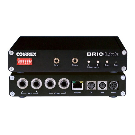
- Page 13 Contact Closures - Provides for 4 contact closure triggers, and 4 open-drain style contact clo- sure outputs. RS-232 - Provides serial data I/O across the IP link. Data rate is configurable. Power - 4-Pin connector for attachment of Comrex approved DC power adapter. Requires 24 V DC @ 1 A.
- Page 14 PaneL DIagRam anD DesCRIPtIons FIguRe 2 DIP Switches - 8 individual DIP switches allow selection of certain operational parameters (see DIP Switch Settings on Page 16). Left/Mono I/O Level Indicator - Tri-color LED shows left channel input or output level. Right I/O Level Indicator - Tri-color LED shows right channel input or output level. Ready/Status LED - Bi-color LED shows Ethernet carrier loss (Red) or valid connection state (Green).
- Page 15 To use AES3, the front panel DIP switches must be set appropriately. AES3 input connections can be at 32, 44.1 or 48 kHz. The front panel DIP switches must be set appropriately. On the BRIC-Link, the output audio sample rate automatically locks to the input sampling rate.
- Page 16 Pin 7 Input #3 Pin 8 Input #4 Pin 9 Ground DIP swItCh settIngs BRIC-Link has a set of eight DIP switches used for audio and indicator configuration. DIP Switch # Function Default (Down) Analog/AES3 Input Select Analog Analog/AES3 Output Select Analog...
- Page 17 After determining the IP Address of the BRIC-Link, open any computer’s web browser on the same network as BRIC-Link. Type the IP address in the browser URL to navigate to the BRIC-Link’s web interface. Log in to BRIC-Link with any user name and, if it has not been changed, the default password “comrex” (lowercase).
- Page 18 RECEIVING INCOMING CONNECTIONS By default, BRIC-Link is set to automatically answer incoming calls, whether or not Switchboard is used to make them. Incoming calls will appear in your connections list while they are active. They can be disconnected locally by highlighting them and clicking “Disconnect”.
- Page 19 IP configuration. Please note: In order to configure a BRIC-Link unit for the first time (without knowing the unit’s IP address), Device Manager must be run on a computer located on the same network (e.g. physical LAN connection) as the unit itself.
- Page 20 Set up ethernet and WireleSS Generally, it is recommended to configure the Ethernet port of a BRIC-Link for a static IP. This will facilitate access to the Web-based Interface with a browser and allow for easier configuration of routers or firewalls (if necessary).
- Page 21 Figure 8 netWork conFiguration UPDATING FIRMWARE USING DEVICE MANAGER While Device Manager is open and synced to a codec, it’s a good time to check to see if an update is available for the product. To do this, select the Firmware tab, shown in Figure 9 below. The unit’s current firmware and the most recent version of firmware for the unit are listed at the top of the tab (1 in Figure 9).
- Page 22 Selecting this will allow changing of the primary Ethernet settings in the same way as Toolbox. Once the IP address is set up via the Device Manager, the rest of the setup and operation of the BRIC-Link is done...
- Page 23 Figure 10 netWork recoVery mode...
- Page 24 CONFIGURING THE BRIC-LINK LOGIN Upon connection to the BRIC-Link, a login screen will appear, Figure 11. Any username can be chosen with the default password: comrex. This will access the Main User Interface display. Figure 11 web interFace Login INTERFACE PAGE SECTIONS There are two parts to the primary interface screen (Figure 12): •...
- Page 25 In the event that a stored unit is no longer desired, it can be deleted through the Trash Icon option. The Connections tab will display Name and Status information of a remote Comrex codec when it has initiated a connection to the BRIC-Link.
- Page 26 Performance->Active Connection described in the next section. PERFORMANCE TAB The Performance Tab includes information on data transmission and reception rates from BRIC-Link to active remote connections. This allows for real-time monitoring of network quality during connections. ACTIVE CONNECTIONS Clicking the header “Active Connection”...
- Page 27 CODEC CHANNEL FIELD Clicking on the Codec Channel field delivers information on the BRIC-Link’s total receive rate and transmit rate, including information for multiple connections when applicable. When multiple transmit connections are active, this will show an aggregate rate of all outgoing connections (Figure 16).
- Page 28 The CrossLock Stats are similar to the information available on the Active Connections graph, which shows streaming performance without regard to the CrossLock layer. The CrossLock Stats show finer details about network performance in both directions than can be obtained through the Active Connections graph. CrossLock stats are shown for both the data being transmitted from the local codec and the data being received by the local codec.
- Page 29 CROSSLOCK SETTINGS Clicking the CrossLock Settings field during an active connection will display the CrossLock sliders. There is a slider available for transmit and receive operation. For most CrossLock connections, the sliders should be left at their default Automatic Delay Mode settings. But during connections on unusual networks, these sliders are designed to quickly adjust the current delay settings.
- Page 30 It is often unnecessary to create any new profiles since BRIC-Link ships with a set of factory-default profiles that cover most users. This tab allows for creating custom profiles when necessary. Please remember, though, that these profile settings only apply to connections initiated from BRIC-Link.
- Page 31 Next is the Channel option (3 in Figure 22), which allows for selecting between a standard Comrex IP connection (BRIC normal) or one of the other connection modes offered by BRIC-Link. Note that when using the CrossLock reliability layer, BRIC Normal mode is chosen here, as this is the protocol that runs with the CrossLock VPN.
- Page 32 Using this menu, users can select the encoder used to send audio from this BRIC- Link (local) as well as the encoder used to send audio to this BRIC-Link (remote). The default value of the remote encoder is to follow the local encoder (i.e., it will send exactly the same codec mode it receives).
- Page 33 For usage, it should always remain “on”. CrossLock Managed Delay - There are two ways BRIC-Link can calculate its target delay, and, therefore, how much decoder buffer to add. The first is the BRIC-Normal way, and is the default for non-CrossLock connections. Buffer size is set based on a histogram of past jitter performance.
- Page 34 automatically and with no audio interruption. Step down congestion avoidance is not enabled in the Linear PCM mode. UDP Reliability - UDP, the Internet protocol used by BRIC Normal connections, does not have any inherent error correction capability. UDP reliability adds an intelligent algorithm that requests packet resends when appropriate above the base UDP level.
- Page 35 CC Connect Status - Allows for the activation of contact closure #4 out when connected. If this is selected, the signal follows the BRIC-Link front panel Ready light, and will be valid (closed) when a valid connection is present and invalid (open) when no connection is present. The additional options (CC1, CC2, and CC3) allow for assigning a particular remote that will be connected when its corresponding contact closure is engaged.
- Page 36 NTP Enabled - Enables the use of NTP network time synchronization. This setting is set to Yes by default. NTP Server - This allows users to set the address of the NTP server. This is set for 0.comrex.pool.ntp.org by default.
- Page 37 Flow Control - Allows for selection of the flow control method. Default is set to None with options for HW (RTS/CTS) and SW (XON/XOFF). This has no functional effect on BRIC-Link. Parity - Users can select parity protection with this setting. Default is set to None with the additional options for Odd...
- Page 38 BRIC-Link. An outgoing call must be made to a specific port number in the form of IP-ADDRESS:PORT#.
- Page 39 HTTP Accept Incoming Connections - Users can set BRIC-Link to listen for and automatically answer any HTTP incoming calls. This option is set to No by default. IP Port - This option defines the incoming UDP port—the number to be used for incoming HTTP connections. The default is TCP 8000.
- Page 40 Outgoing calls are defined as TCP when their profile is configured. BRIC-Link normally listens for incoming calls on both TCP and UDP ports, and chooses the first to arrive. If a TCP call is detected, BRIC-Link will attempt to use the same TCP link to transmit in the reverse direction.
- Page 41 Note: Warnings given above about changing port numbers also apply here—calls with mismatched port numbers will fail. MISCELLANEOUS Meter Demo Mode - This setting will put the front panel LED meters into a demonstration mode. This setting is set to No by default.
- Page 42 The primary ethernet port for BRIC-Link is configured for DHCP by default. In this configuration, BRIC-Link will be assigned an IP address from a pool of available IP addresses from the network router upon booting. If BRIC-Link is connected to the Internet, it should display connection information for the Ethernet Port, including IP and DNS server addresses.
- Page 43 Gateway Address, as well as at least one DNS Server Address. Static Route Settings present advanced network configuration for users with complex and multilayered networks. As this is an uncommon need for most users, Comrex recommends users interested in learning more refer to the Static Routing Technical Note at www.comrex.com.
- Page 44 This setting is disabled by default, and Comrex advises users to be cautious when enabling it. If the Ethernet parameters are set incorrectly, it is possible to be locked out of the BRIC-Link, and you will then have to use the Device Manager program‘s Network Recovery Mode (discussed on...
- Page 45 BRIC-Link and ACCESS Codec connections. How CrossLoCk works: a brIef oVerVIew CrossLock is available on BRIC-Link and older products running at least 4.x-level firmware. To understand how CrossLock works, it’s helpful to first focus on non-CrossLock connections as shown in Figure 28. Without CrossLock active, a codec will make BRIC Normal connections to BRIC-Link on port 9000.
- Page 46 9000. The CrossLock connection between the Comrex hardware happens over a single port (9001) but the BRIC Normal connections take place virtually on their usual legacy ports within that VPN. The system will show these virtual connections happening on ports 9000, 9002 and 9003 (these are the BRIC Normal ports), but the only actual connection between hardware is happening on 9001.
- Page 47 This section describes the procedure of making and receiving connections on BRIC-Link via the Comrex Switchboard server. This is the easiest way, but not the only way, to make BRIC-Link connections. Before connections are made this way, you must set up and configure a Switchboard Account as described in Section X.
- Page 48 Once your Switchboard peers are configured, connecting to one is simple: 1. Select the desired Switchboard peer. 2. Make sure the “gear” icon is green. 3. Click “Connect” in the upper right corner. Switchboard connections can be ended on either end of the link, by choosing the active connection in the list and clicking “Disconnect”.
- Page 49 Remotes require selection of a codec profile as seen in Figure 32. The BRIC-Link includes several factory profiles to choose from, each of which enables a full-duplex link. Factory-provided profiles offer commonly used encoders and settings.
- Page 50 ProFIle manager tab baCk uP remote BRIC-Link features an ability to have an automatic backup to a designated remote connection. A specific backup connection (for when the primary fails) is designated when a new remote is created. As shown in Figure 33, selecting the backup option opens a menu allowing selection of other outgoing remotes that have been created.
- Page 51 If the primary remote is restored and BRIC-Link can detect a valid signal, it will automatically disconnect the backup and revert back to the primary remote. To enable Fall Forward, click the “Fall Forward” option in the Edit Remote Settings prompt and select Yes (Figure 33).
- Page 52 SETTING UP YOUR SWITCHBOARD ACCOUNT The Switchboard Traversal Server is a service built and maintained by Comrex on the public Internet that provides users a directory of other users, facilitating connections to devices that would normally have trouble accepting incoming IP connections. Use of Switchboard is free and comes activated from the factory. Use the instructions in the user interface chapters of this manual to configure Switchboard on the BRIC-Link unit.
- Page 53 Note: MultiRack instances must be added to Switchboard individually. Instance 1 Switchboard ID is the same as the unit MAC Address, while Instances 2-5 use the same MAC address, with a suffix added to designate the instance Switchboard ID. As an example, if the primary Ethernet MAC address on a MultiRack is 00:01:40:c0:0d:15, that’s the ID input for MultiRack instance #1.
- Page 54 By default, a master Contact List is created that contains all codecs in an account. Every codec in the fleet uses the master list by default. For users uninterested in segregating codes on their account, the default configuration will work fine. NOTE: Assigning a Contact List to a codec determines what gets displayed in its own list.
- Page 55 FigUre 41 FoLLow contAct LiSt On the next screen, check the Contact List(s) that you want this codec to Follow and press “Update Contact List” (Figure 41). One important point to remember: Following a Contact List on a codec only determines which units get displayed on that codec’s own list.
- Page 56 FigUre 43 ShAre A device To create a Share, click the Sharing tab and then select “Add New Share” (Figure 42). The following screen allows users to choose which codec(s) they want to include in a Share (Figure 43). After making a selection, users will need to enter one of the following to identify the account they wish to Share their unit(s) with: the official name of that account as it’s listed in Switchboard;...
- Page 57 ShAring AccoUntS Finally, while it is possible to delete Shares, Comrex recommends disabling them instead. This will stop the Share and won’t require any future work to recreate it. To disable a Share, simply click the orange Disable button on the bottom right of the Share edit page (Figure 46).
- Page 58 FigUre 47 mULtipLe contAct LiStS If multiple Contact Lists have been designated as “Followed“ on a unit’s Switchboard interface, each Contact List will appear at the bottom of the Connections tab (Figure 47). To view and/or connect to the unit(s) within a list, select the list and press the Open Folder button on the upper right.
- Page 59 FigUre 49 bULK ActionS To do this, press the Bulk Action button in the bottom right corner of the Contact List tab (Figure 49). The three steps to create a Bulk Action are: 1. Choose the type of action to perform. 2.
- Page 60 FigUre 51 bULK device SeLection After completing this step, specify whether to target the units that are a part of a Contact List or the units that are Following that list (i.e., the option in the yellow-outlined box on the middle-left of the above figure). Note: Bulk Actions can ONLY be performed on ENTIRE Contact Lists.
- Page 61 Switchboard Theory and Concepts Switchboard is useful because it’s not always simple to connect two devices which are essentially “peers” over the Internet. There are two major reasons for this. First, to initiate a stream to a device over the Internet requires knowing its IP address.
- Page 62 The challenges of connecting codecs behind NAT routers will be addressed in more detail shortly. For now, remember that one of the problems NAT servers add is that private IP addresses delivered to codecs (and the only addresses of which the codecs are aware) have no bearing on the public addresses seen from the Internet. In extreme scenarios, several layers of address locality can be stacked, assuring that the IP address assigned to a device is several degrees removed from the public IP address used for connections.
- Page 63 This can work well for fixed installations, but it’s not always an easy task to obtain that kind of security access on corporate routers. Additionally, forwarding functions are implemented differently depending on the hardware. One can easily imagine the complications of obtaining or managing port forwarding on the LAN when arriving at a new remote venue.
- Page 64 A good way to think of this is that an outgoing packet “punches a hole” in the router, through which authorized reply packets may be returned to the codec for a limited time (Figure 55). FigUre 55 bidirectionAL commUnicAtion Switchboard aids in breaking through these different types of routers for incoming calls. Because it is in constant contact with all subscribed codecs, it can send and receive test patterns to determine whether one or more NAT routers exist on a link and what type they are.
- Page 65 BRIC-Link can be configured for “always on” operation. This allows for constant STL communication and operations requiring long-term connections. In BRIC Normal mode (the default mode of operation), BRIC-Link transfers all its audio data via the UDP 9000 protocol. This is in contrast to most web-based connections like browsing and email, which use the bidirectional TCP protocol.
- Page 66 The BRIC-Link has the capability to automatically make a backup IP connection if there is a failure in the primary connection. This is called Fallback, and is an option chosen after defining a new Remote connection.
- Page 67 Additionally, there is a box in the Change Remote Settings tab labelled Automatically fall forward. If this box is checked, the system will constantly attempt to reconnect the primary remote while connected to the fallback remote. If connection is successful, the connection to the “Fallback” will be terminated.
- Page 68 ABOUT THE ALGORITHMS XII. When building profiles for BRIC-Link and remote devices, there are several different audio encoder options to use for each direction of the link. Different audio encoder options each have advantages and disadvantages, depending on the situation. The following is a refresher on audio codec algorithms to assist in making the best choice.
- Page 69 Special CBR modes are offered for compatibility with Tieline products—avoid these in other applications. Due to its versatility in audio quality and low networking drain, Opus is the default profile for Comrex codecs. *Linear PCM and FLAC are only supported for CrossLock connections on devices running 4.3-p4 firmware or...
- Page 70 Algorithm Comparison Chart for ACCESS NX Rack Required Coding Audio Bitrate Delay Bandwidth 64 kb/s 69 ms 20 kHz D1 Mono 96 kb/s 69 ms 20 kHz D2 Stereo 128 kb/s 69 ms 20 kHz D3 Dual Mono allows independent programming to be sent on both L&R channels 128 kb/s 69 ms 20 kHz...
- Page 71 MULTISTREAMING XIII. BRIC-Link supports the ability to run one encoder per connection, but this single encoder stream may be sent to up to three destinations simultaneously. This capability is referred to as a Multistream, as the encoder creates a separate but identical outgoing stream to each decoder. (Note: A User’s Internet connection must be able to support these streams.
- Page 72 BRIC-Link A. BRIC-Link C and D will each define a profile with their Local Encoders turned Off, and assign them to A. BRIC-Link B should connect first. When C and D connect, they will hear the same stream as B, regardless of how their Remote Encoders are set in their profiles.
- Page 73 IP MULTICAST XIV. IP Multicast is an efficient way of delivering BRIC-Link digital audio streams to multiple locations. This involves relying on the network to distribute the stream to the locations that require it, rather than creating an independent stream for each user.
- Page 74 Time-to-Live (TTL) is a variable set by Multicast encoders to determine how long a packet is processed before it is dropped by the network. The default value of TTL in BRIC-Link is 0, which limits its use to within a LAN environment.
- Page 75 STREAMING SERVER FUNCTION BRIC-Link has the ability to act as a streaming server, delivering AAC and HE-AAC to compatible PC-based media players. Currently tested media players include WinAmp, VLC, and Windows Media Player 12 and up. By default, streaming server functionality is turned off. To enable it, go to the System Settings tab of the User Interface and choose HTTP Settings option.
- Page 76 AAC algorithm supported by players, then when a stream is requested it will be delivered using the same encoder as the BRIC connection, regardless of the HTTP settings. If the BRIC-Link encoder is Linear or FLAC, the stream request will be rejected.
- Page 77 In brIC-LInk BRIC-Link does not fully comply with EBU3326, as it does not feature the mandatory MPEG Layer II codec. Aside from this, BRIC-Link has been tested to be compatible with several other manufacturer’s devices using encoders supported by both products.
- Page 78 Several free servers exist that can offer registration, like Onsip.com. The BRIC-Link allows EBU3326/SIP calls to be placed or received with or without registration on a SIP server. If registration is not enabled, connections are made directly to the compatible device by dialing its IP address, just like in BRIC Normal mode.
- Page 79 • The password on the SIP account. Figure 64 shows how this information can be applied: by enabling the Use SIP Proxy option under EBU 3326/SIP on the Systems Settings tab. FIgure 64 ebu3326/SIP SettIngS Once this information is correctly entered, a new field appears in the “Registration Status” box located on the Connections tab (Figure 65).
- Page 80 The basic entries provided will allow support for the vast majority of EBU3326/SIP based applications. There are inevitably situations where the defaults won’t work, however. Comrex has provided some advanced options that can help. These options are located in the Systems Settings and can be made visible by selecting the Advanced box: •...
- Page 81 Incoming calls to codecs behind routers are complicated by the need to forward ports on the router to the codec. In the case of SIP, this must be three discrete ports (for Comrex codecs these are UDP 5060, 5014 and 5015)<6014 and 6015 with 3.0 firmware>.
- Page 82 Another technique for working around the SIP-Router issue is by using a protocol called STUN. This can be enabled in Comrex codecs in the Advanced EBU3326/SIP options and allows for the codec to learn its public IP address. It does this by contacting a STUN server on the Internet (the default one is maintained by Comrex) and requesting its Public IP.
- Page 83 Gnu Public License (GPL). For more information on GPL see http://www.gnu.org. As per the GPL, source code for this software is available on request from Comrex on CD-ROM or other electronic format. To obtain this software please contact our support department at +1 978 784 1776. We retain the right to charge a small handling fee for distribution of this software.
- Page 84 During the warranty period, we will repair or, at our option, replace at no charge a product that proves to be defective, provided you obtain a return authorization from Comrex and return the product, shipping prepaid to Comrex Corporation, 19 Pine Road, Devens MA 01434 USA. For return authorization, contact Comrex at 800-237- 1776 or 978-784-1776 or email techies@comrex.com.
- Page 85 OR CONSEQUENTIAL DAMAGE RESULTING FROM THE USE OF THE PRODUCT INCLUDING LOSS OF PROFITS, LOSS OF SAVINGS, LOSS OF USE OR INTERRUPTION OF BUSINESS EVEN IF COMREX CORPORATION OR ANY OF ITS SUPPLIERS HAS BEEN ADVISED OF THE POSSIBILITY OF SAME. IN NO EVENT SHALL COMREX CORPORATION AND/ OR ITS SUPPLIERS’...
- Page 86 Comrex provides this service, free of charge and at will. As such, Comrex offers no warranty as to availability of this server or of its function. Comrex reserves the right to discontinue availability of this service at any time. Comrex also reserves the right to remove any account from the server at http://switchboard.comrex.com at any time for...
- Page 87 Place of Issue: Devens, Massachusetts Date of Issue: January 23, 2006 Equipment: Comrex BRIC-Link Comrex Corporation, located at 19 Pine Road, Devens, MA in the United States of America hereby certifies that the Comrex BRIC-Link bearing identification number US:DXDMD01BACCRK complies with the Federal Communications Commission’s (“FCC”) Rules and Regulations 47 CFR Part 68, and the Administrative Council on Terminal...
- Page 88 ConformIty for r&tte dIreCtIve Manufacturer’s Name: Comrex Corporation Manufacturer’s Address: 19 Pine Road Devens, MA 01434 hereby declare on our sole responsibility that the product: Comrex BRIC-Link Digital Audio Codec to which this declaration relates is in conformity with the essential requirements and other relevant requirements of the R&TTE Directive (1999/5/EC).
- Page 89 (5.0). To be certain of the number of devices that may be connected to a line, as determined by the total RENs, contact the local telephone company. The REN for the Comrex BRIC-Link is 0.1, and is shown as the digits represented by ## in the product identifier US:DXDMD###ACCRK.
- Page 90 This setting has no effect on normal BRIC-Link functions, which continue to operate as before.
- Page 91 • Outgoing Connections - Build a profile using the Profile Manager on the BRIC-Link and select a Channel Mode of Standard RTP. Then choose an Xstream-compatible encoder for the outgoing call. The Xstream will control what type of stream, if any, is returned to the BRIC-Link.
- Page 92 Appendix B - BRiC-Link on UnidiReCtionAL netwoRks Under most circumstances, BRIC-Link requires an IP path in both directions for successful connections, even when audio is being sent only one-way. For networks that provide data only in one direction, it is possible to use Standard RTP mode to establish and maintain these links.
- Page 93 APPENDIX C - INformAtIoN for It mANAgErs The purpose of this appendix is to describe all open ports and services available on the Comrex BRIC-Link. The Comrex BRIC-Link is a device designed to move real-time, wideband audio over IP networks. The main network interface is 1000BaseT-Ethernet.
- Page 94 UDP ports for each MultiRack Instance. UDP 9000 is the default port for BRIC Normal connections. Instance #1 on MultiRack will use the UDP 9000 port by default. Comrex generally recommends End Users with MultiRack then use UDP 9002-9005 for instances #2-5 respectively, leaving UDP 9001 open for Crosslock.
- Page 95 Only one account is required for each group of codecs. Once a username and password are provided, navigate to switchboard.comrex.com in a web browser. When first accessing Switchboard, there will be a notice stating that no units have been added to the account. By clicking on Add New Unit, a dialogue box will ask for the Switchboard ID (Ethernet MAC address) of the MultiRack.
Need help?
Do you have a question about the BRIC-Link and is the answer not in the manual?
Questions and answers