Advertisement
Quick Links
Quick Start Guide
This document describes how to quickly set up and
use BRIC-Link in its most common, point-to-point
mode. More detailed instructions are contained in
Setting up the Hardware
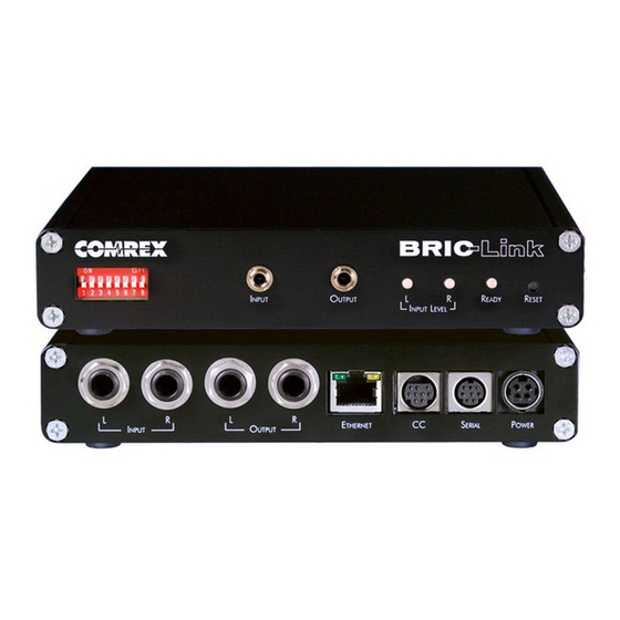
Figure 1 – Rear Panel Diagram and Descriptions
1
1) Left Audio/AES3 Input: Accepts professional level,
balanced analog audio, or if confi gured, AES3
stereo digital audio for input.
2) Right Audio Input: Accepts professional level,
balanced analog audio.
3) Left Audio/AES3 Output: Delivers professional level,
balanced analog audio, or if confi gured, AES3
stereo digital audio for output.
At a minimum, BRIC-Link needs a source of power, an
audio connection, and a network connection.
Audio connections on the 1/4" jacks are wired in the
following fashion:
Tip
Balanced Audio +
Ring
Balanced Audio -
Sleeve
Ground
With a nominal input level of 0dBu (+20 dBu full scale).
2
3
4
the manual on the CD shipped with the unit. It may
also be downloaded from the Comrex web site at
www.comrex.com
5
4) Right Audio Output: Delivers professional level,
balanced analog audio.
5) Ethernet: 10/100baseT connection for network
connections.
6) Power: 4 Pin connector for attachment of Comrex
approved DC power adapter. Requires 24V DC @ 1A
You may apply AES3 digital audio to the left I/O
connectors if dip switch #1 (Input) and #2 (output)
are up.
Audio inputs should be
applied and levels checked
with Dip Switch #4 down.
If the audio indicators are
showing red, it indicates
the level is approaching or
reaching clipping stage. It is OK for audio levels to
reach the yellow stage often.
The Ethernet connector is a standard 10/100baseT.
A normal patch cord, such as used for a computer,
should be connected here.
6
Advertisement

Subscribe to Our Youtube Channel
Related Manuals for Comrex BRIC-Link


Summary of Contents for Comrex BRIC-Link
- Page 1 DC power adapter. Requires 24V DC @ 1A balanced analog audio, or if confi gured, AES3 stereo digital audio for output. At a minimum, BRIC-Link needs a source of power, an You may apply AES3 digital audio to the left I/O audio connection, and a network connection.
- Page 2 Using the BRIC-Link Device Manangera Initial IP confi guration is handled using the Windows- Once power is applied to BRIC-Link, you have fi ve based BRIC-Link Device Manager software. This minutes to confi gure the IP settings. After fi ve minutes,...
- Page 3 (when they’re not busy with other users). We maintain two CD players on these So now it’s time to make a connection on BRIC-Link. codecs, feeding voice and music audio respectively. We will assume that the network and audio connec- tions have been made.
- Page 4 Controlling BRIC-Link via the Web-Based Interface (cont.) To create your own outgoing connection, click Store Once your remote connection entry is correct, it’s New Remote as shown to get the entry pop-up. Choose simply a matter of pointing and clicking to connect and a name for the remote (e.g..
Need help?
Do you have a question about the BRIC-Link and is the answer not in the manual?
Questions and answers