Thermo Scientific RO-20 Operating Manual
Aa ion chamber
Hide thumbs
Also See for RO-20:
- Operating instructions manual (50 pages) ,
- Operating instructions manual (114 pages)
Table of Contents
Advertisement
Quick Links
Advertisement
Table of Contents

Related Manuals for Thermo Scientific RO-20


Summary of Contents for Thermo Scientific RO-20
- Page 1 Operating Manual RF-000-xxxxxx RO-20 AA Ion Chamber...
- Page 3 REVISIONS SHEET: Rev. Rev. Dept. Name Rev. Cat. Explanation State resp. page *) Category C: editorial correction I: clearing improvement A: substantial amendment Explanations must be given, at least with Category A.
-
Page 4: Table Of Contents
CONTENTS: Introduction..................1-1 Instrument Description ......................1-1 Measuring Units........................1-2 Detector Specifications ......................1-2 1.3.1 Size ..........................1-2 1.3.2 Fill........................... 1-2 1.3.3 Wall ..........................1-2 1.3.4 Window .......................... 1-2 1.3.5 Beta Shield........................1-2 1.3.6 Radiation Detected ......................1-2 1.3.7 Photon Energy Response ....................1-2 1.3.8 Examples of Beta Response ................... - Page 5 Operation the Instrument ....................... 2-2 2.3.1 Checking the Zero Setting ....................2-2 2.3.2 Minimizing Deflection ....................2-2 2.3.3 Ion Chamber ........................2-2 2.3.4 Radiation Overexposure ....................2-2 2.3.5 Electronic Circuitry ......................2-2 Theory of Operation ..............3-1 General Theory ........................3-1 Functional Theory........................
- Page 6 TABLE OF FIGURES: Figure 1-1: Model RO-20 Ion Chamber....................1-1 Figure 1-2: Nominal photon energy response ..................1-3 Figure 3-1: Connector / battery board component layout ..............3-1 Figure 3-2: Basic operation of the circuit..................... 3-2 Figure 3-3: Detector board component layout..................3-3 Figure 3-4: Main circuit board layout ....................
-
Page 7: Introduction
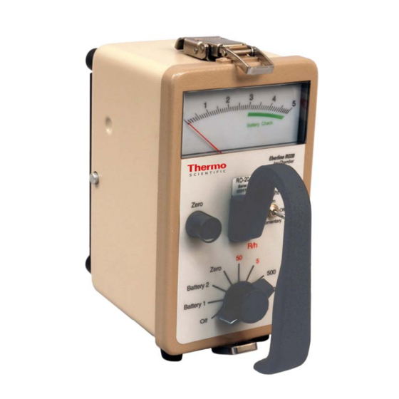
1-1) is a portable air ion chamber instrument used to detect beta ( ß ), gamma (γ) and x-ray radiation. The RO-20 has five linear ranges of operation to measure exposure rate for x-ray and gamma radiation. The ion chamber is vented to atmospheric pressure. -
Page 8: Measuring Units
The RO-20 has the ranges labeled in exposure rate R/h. The ranges are 50 R/h,5 R/h and 500mR/h,50mR/h,5 mR/h. The RO-20 chamber is designed to have a flat energy response in roentgen units. Use the procedure given in this manual for calibration of the instrument. The calibration controls on the main circuit board are marked from 5 through 50 k, which corresponds to the 5 ranges (expressed in R/h). -
Page 9: Examples Of Beta Response
In the following examples, the RO-20 had been calibrated to Cs (slide closed), with the slide facing the source. • ±30% from 8 keV to 1.3 MeV, with the open slide facing the source. • ±15% from 33 keV to 1.3 MeV, with the closed slide facing the source. -
Page 10: General Specifications
• Function Switch with Off, Zero, and Battery checking positions. • The Zero Knob is used to set the meter to zero when the Zero position of the Function Switch is selected, or when the detector is not in a significant radiation field. RB-XXX-XXXXXX E RO-20 Löw 08.10.2008... -
Page 11: Internal
• Main power: Five AA cells. • Chamber bias: 3 ea 12V alkaline batteries = 36V. • Life: AA cells, widely variable according to RO-20 usage and battery type. • Typical alkaline: mR/h ranges, 2500 hrs; all other positions, 130 hrs. -
Page 12: Weight
1.4.7.5 Weight Approximately 3.6 pounds (1.63 kg) with alkaline AA cells. 1.4.7.6 Size 4.2 in. wide x 7.9 in. long x 7.7 in. high (10.7 cm x 20.1 cm x 19.6 cm), including handle. RB-XXX-XXXXXX E RO-20 Löw 08.10.2008... -
Page 13: Operation
Five variable resistors, one for each range, provide internal calibration controls. Using the Instrument The higher radiation field strengths measurable by the RO-20 can cause personal injury in a short time. Before using the instrument check Battery 1 (AA cells) and Battery 2 (l2V alkaline cells). The meter should indicate in the green Battery Check arc. -
Page 14: Operation The Instrument
2.3.1 Checking the Zero Setting The zero setting of the RO-20 may be checked in any radiation field by selecting the Zero position of the Function Switch. If a minor offset from zero exists on the most sensitive range when in a known insignificant field, the Zero Knob may be used to remove the offset. - Page 15 1.08 1.04 0.96 0.93 9000' 1.40 1.35 1.30 1.25 1.21 1.16 1.12 1.08 1.04 0.96 10,000' 1.45 1.40 1.35 1.30 1.26 1.21 1.17 1.12 1.08 1.04 (1) Multiply reading in feet by correction factor shown. Ro-20 RB-XXX-XXXXXX E Löw 08.10.2008...
- Page 16 1.44 1.40 1.36 1.32 1.28 1.24 1.20 1.16 1.13 1.10 1.06 1.03 0.97 3250 1.49 1.44 1.40 1.36 1.32 1.28 1.24 1.20 1.16 1.13 1.10 1.06 1.03 Multiply reading in meters by correction factor shown. RB-XXX-XXXXXX E RO-20 Löw 08.10.2008...
-
Page 17: Theory Of Operation
A common line is used as a reference for all the electronic circuits. This common line is held approximately 36 volts negative with respect to the instrument chassis. Figure 3-1: Connector board component layout Ro-20 RB-XXX-XXXXXX E Löw 08.10.2008... -
Page 18: Functional Theory
–14 An idealized air chamber, the size of the one used on the RO-20, produces a little over 2x10 amps per mR/h at the standard temperature and pressure of 0 C and 760 mm of Hg. At 5 –13... -
Page 19: The Circuit
Zero Knob. That relay is closed when in the two battery-check positions (to provide maximum battery load), and in the Zero position of the Function Switch. It is open in the other Function Switch positions Figure 3-3: Detector board component layout Ro-20 RB-XXX-XXXXXX E Löw 08.10.2008... -
Page 20: Figure 3-4: Main Circuit Board Layout
AA cell battery’s positive end. When checking the three 12V batteries, amplifier A201-12,13,14 is used to reflect the opposite polarity of the input from the more positive chassis potential. RB-XXX-XXXXXX E RO-20 Löw 08.10.2008... - Page 21 Amplifier A201-1,2,3 is used to hold the relay coils at common potential whenever the relays are not actuated, helping reduce leakage currents when using the mR/h ranges. Amplifier A201-5,6,7 provides a slow reduction of relay coil current when switching to the mR/h ranges in order to minimize transients. Ro-20 RB-XXX-XXXXXX E Löw 08.10.2008...
-
Page 23: Maintenance
4. Maintenance Preventive Maintenance Refer to while performing the procedures described in this chapter Figure 4-1 Figure 4-1: Interior View, RO-20 4.1.1 Batteries Replace the AA cells when Battery 1 check indicates near the left end of the meter’s green arc. -
Page 24: Desiccant
4.1.3 Calibration For maximum accuracy, the RO-20 should be calibrated at approximately the same air pressure as is expected for its use. If the conditions for calibration and for use are necessarily different, an offset may be used during calibration so that the instrument will read properly when put to use. -
Page 25: Circuit Checks
1. Select the Zero position on the Function Switch and zero the meter. 2. Remove the plastic cover on the side of the can and position the RO-20 so that the ion chamber is in a gamma field of known intensity. - Page 26 To remove the chamber board assembly: 1. Gently unplug the cable that connects the assembly to the battery board. 2. Unsolder the connections to the guarded feedthrough assembly. 3. Remove the three nuts holding the board and lift it out. RB-XXX-XXXXXX E RO-20 Löw 08.10.2008...
-
Page 27: Reassembly
The aluminized Mylar face on the bottom of the can is one mil (.001 in., 25 microns) thick. It is glued to the can using electrically conductive adhesive. If only one side of the Mylar is coated with aluminum, that side must be positioned against the can. Ro-20 RB-XXX-XXXXXX E Löw 08.10.2008... - Page 28 Lay the Mylar on the chamber and slip the clamp ring over it, making as smooth a face as possible. RB-XXX-XXXXXX E RO-20 Löw 08.10.2008...
-
Page 29: Troubleshooting
Chapter 3: “Theory of Operation” are the primary troubleshooting aids. Check the batteries. The RO-20 has only four active circuit components, amplifiers A101 and A201, the voltage regulator A203 and the reference divider A202. A quick check with a voltmeter will determine whether the outputs of A203 and A202 are proper. The two amplifiers are in sockets for easy substitution. - Page 30 RB-XXX-XXXXXX E RO-20 Löw 08.10.2008...
-
Page 31: Figure 4-2: General Schematic
Figure 4-2: General schematic Ro-20 RB-XXX-XXXXXX E Löw 08.10.2008... -
Page 33: Appendix A - Electronics And Parts List
5. Appendix A - Electronics and Parts List Table 5-1 lists the electronic items incorporated in the RO-20, and the parts required for normal electronic repair. When ordering parts from Thermo Fisher Scientific, specify instrument model number, serial number, reference designation, value, and Thermo Fisher Scientific part number. - Page 34 YX11502001 RO20 CAN ASSEMBLY WITH NO CAL HOLE ZP10448011 HANDLE POWDERCOATED ZP10894010 RO-20 ZERO KNOB GUARD ZP11498003 RO20 COVER, PAINTED w/o OVERLAY ZP11498012 GASKET, COVER, RO-20 ZP11498014 COVER OVERLAY, RO-20 ZP11502004 RO-20 SLIDE RB-XXX-XXXXXX E RO-20 Löw 08.10.2008...
- Page 35 SACHWORT-REGISTER: Meßnetzprogramm NetView RF-019-950313 Schl/Ff 13.03.1995...
- Page 37 Environmental Instruments Division Thermo Electron (Erlangen) GmbH Radiation Measurement & Security Frauenauracher Straße 96 Postfach/P.O. Box 16 60 D-91056 Erlangen, Germany D-91051 Erlangen, Germany www.thermo.com +49 (0)9131 998-0 info.rmp.erlangen@thermofisher.com +49 (0)9131 998 475 fax...
Need help?
Do you have a question about the RO-20 and is the answer not in the manual?
Questions and answers