Table of Contents
Advertisement
Quick Links
Advertisement
Table of Contents

Related Manuals for Lutron Electronics TM-946


Summary of Contents for Lutron Electronics TM-946
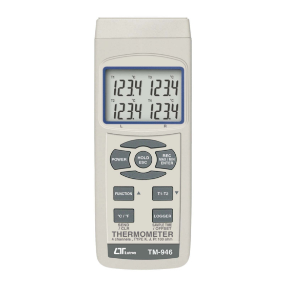
- Page 1 T1, T2, T3, T4, T1-T2, Type J/K, Pt 100 ohm 4 CHANNELS THERMOMETER Model : TM-946...
-
Page 2: Table Of Contents
TABLE OF CONTENTS 1. FEATURES..............1 2. SPECIFICATIONS............1 3. FRONT PANEL DESCRIPTION........5 4. GENERAL MEASURING PROCEDURE......6 4-1 Type K measurement.......... 6 4-2 Type J measurement..........7 4-3 Pt 100 ohm measurement........7 4-4 T1-T2 measurement..........8 4-5 Data Hold............. 8 4-6 Data Record (Max, Min reading)......8 4-7 Data Logger............9 5. -
Page 3: Features
1. FEATURES * Type K/J, Pt 100 ohm, measurement with 4 display. * Show 4 channels display on the LCD at the same time. * Type K : -199.9 to 1370 ℃ * Type J : -199.9 to 1210 ℃ * Pt 100 ohm : -199.9 to 850.0 ℃... - Page 4 Display LCD size : 52 mm x 38 mm Show 4 channels display on the display at the same time. Display Unit ℃ ℉ Resolution 0.1 /1 , 0.1 /1 ℃ ℃ ℉ ℉ Channels T1, T2, T3, T4, T1-T2. Sensor type Type K thermocouple probe.
- Page 5 Over Indication Show " ". Data Hold Freeze the display reading. Memory Recall Maximum & Minimum value. Sampling Time Approx. 1 second. of display Power off Auto shut off saves battery life or manual off by push button. Data Output RS 232 PC serial interface.
- Page 6 2-2 Electrical Specifications (23± 5 ℃ Type K, Type J thermocouple Sensor Reso- Range Accuracy Type lution Type K 1 ℃ 1000 to 1370 ℃ ± ( 0.5 % + 1 ℃ 0.1 ℃ -199.9 to 999.9 ℃ 1 ℉ 1000 to 2498 ℉...
-
Page 7: Front Panel Description
3. FRONT PANEL DESCRIPTION Fig. 1 3-1 Display 3-2 Power button 3-3 Hold/ESC button 3-4 REC/Enter button 3-5 Function button ( button, L button ) ▲ button ( Send, CLR button ) ℃ ℉ 3-7 T1-T2 button ( button, R button ) ▼... -
Page 8: General Measuring Procedure
4. GENERAL MEASURING PROCEDURE 4-1 Type K measurement 1)Power on the meter by pressing the " Power button " ( 3-2, Fig. 1 ) once ( > 1 sec ). * After already power on the meter, pressing the " Power button " once ( > 1 sec ) will turn off the meter. -
Page 9: Type J Measurement
4)Insert the Type K probes into the " T1, T2, T3, T4 input socket " ( 3-9, Fig. 1 ). The LCD will show the 4 channels ( T1, T2, T3, T4 ) temperature value at the same time. * If the certain channels do not insert the temperature probes, the relative channel display will show over range "... -
Page 10: T1-T2 Measurement
* The Pt 100 ohm measurement only allow max. two channels ( two probes ) input. 4-4 T1-T2 measurement If the meter already insert two probes : Type K, Type J : T1, T2 input socket Pt 100 ohm : PT1, PT2 input socket Pressing the "... -
Page 11: Data Logger
* When the " REC " symbol on the display : a) Press the " REC Button " ( 3-4, Fig. 1 ) once, the " REC MAX " symbol along with the maximum value will appear on the display. If intend to delete the maximum value, just press the "... - Page 12 b)Auto Data Logger ( Sampling time should select to 1 second to 59 minutes and 59 seconds ) Press the " Logger button " ( 3-8, Fig. 1 ) once to start the Data Logger function. The REC symbol will flash per 2 second and the beeper will sound when save the data into the memory.
-
Page 13: Advanced Measuring Procedure
Note : 1) If intend to change the data logger sampling time, please refer section 5-1, page 11. 2) If intend to know the space of balance data numbers into the memory IC, please refer section 6, page 14. 3) If intend to clear the saving data from the memory please refer section 5-2, page 13. - Page 14 1)Pressing " R button " ( 3-7, Fig. 1 ) once, the display will show as example : SP-t minutes seconds adjustment adjustment ( flash ) * The " seconds digits " will be flashed, use the " ▲ button "( 3-5, Fig. 1 ) " button "...
-
Page 15: Clear The Existing Saving Data From The Memory
5-2 Clear the existing saving data from the memory 1)Pressing " CLR button " ( 3-6, Fig. 1 ) continuously at least two seconds then release, the display will show : SEnd 2)Pressing " R button " ( 3-7, Fig. 1 ) once, the display will show as example : the data no. -
Page 16: Send The Data Out From The Meter
6. SEND THE DATA OUT 1)To send the data out from the meter, should exit the " Hold function " and the " Record function " at first. 2)Pressing " Send button " ( 3-6, Fig. 1 ) continuously at least two seconds then release, the display will show : SEnd 3)Pressing "... - Page 17 Value will increase up from zero until reach to the existing save data no. SEnd Then LCD will change to the following screen. The data no. that are saved into the memory. 15728 Balance of empty data no. * During send the data out, if pressing the " Send button " ( 3-6, Fig.
-
Page 18: Offset Adjustment
7. OFFSET ADJUSTMENT 7-1 Type K, Type J offset adjustment 1) Set the function to Type K ( Type J ). 2)Insert the probe to the T1 input socket. 3) Pressing " Offset button " ( 3-8, Fig. 1 ) continuously at least two seconds then release, the display will show : SP-t... -
Page 19: Pt 100 Ohm Offset Adjustment
7-2 Pt 100 ohm offset adjustment 1)Set the function to Pt 100 ohm. 2)Insert the Pt 100 ohm probe to the PT1 ( PT2 ) input socket. 3)Pressing " Offset button " ( 3-8, Fig. 1 ) continuously at least two seconds then release, the display will show : SP-t 4)Pressing "... -
Page 20: Auto Power Off Disable
* Use the " button "( 3-5, Fig. 1 ) " button " ( 3-7, ▲ ▼ Fig. 1 ) to adjust the desiring value on right bottom display. * Pressing " Enter button " ( 3-4, Fig. 1 ) once, both bottom display will flashing 4 times then return to normal measuring screen and finish the offset adjustment procedure. -
Page 21: Rs232 Pc Serial Interface
9. RS232 PC SERIAL INTERFACE The instrument has RS232 PC serial interface via " RS 232 out terminal " 3.5 mm terminal ( 3-12, Fig. 1 ). The data output is a 16 digit stream which can be utilized for user's specific application. A RS232 lead with the following connection will be required to link the instrument with the PC serial port. - Page 22 Each digit indicates the following status : Start Word = 02 Function : T1, T2, T3, T4 When send the T1 value, D13 = 1 When send the T2 value, D13 = 2 When send the T3 value, D13 = 3 When send the T4 value, D13 = 4 Function : T1, T2, T1-T2 When send the T1 value, D13 = 1...
-
Page 23: Battery Replacement
10. BATTERY REPLACEMENT 1)When the left corner of LCD display show " ", it is necessary to replace the battery. However, in-spec. measurement may still be made for several hours after low battery indicator appears before the instrument become inaccurate. 2)Open the "... - Page 24 Data Acquisition * The SW-U801-WIN is a multi software displays ( 1/2/4/6/8 displays ) SW-U801-WIN powerful application software, provides the functions of data logging system, text display, angular display, chart display, data recorder high/low limit, data query, text report, chart report.. .xxx.mdb data file can be retrieved for EXCEL, ACESS.., wide intelligent applications.
Need help?
Do you have a question about the TM-946 and is the answer not in the manual?
Questions and answers