Table of Contents
Advertisement
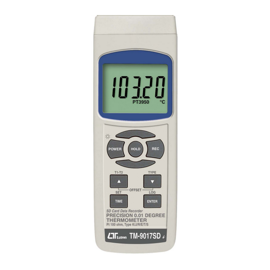
PT 100 ohm, type K/J/T/R/E/S
PRECISION 0.01°
THERMOMETER
Model : TM-9017SD
Your purchase of this PRECISION THERMOMETER marks a step
forward for you into the field of precision measurement.
Although this METER is a complex and delicate instrument, its
durable structure developed. Please read the following
instructions carefully and always keep this manual within easy
reach.
OPERATION MANUAL
Advertisement
Table of Contents

Subscribe to Our Youtube Channel
Related Manuals for Lutron Electronics TM-9017SD


Summary of Contents for Lutron Electronics TM-9017SD
- Page 1 PT 100 ohm, type K/J/T/R/E/S PRECISION 0.01° THERMOMETER Model : TM-9017SD Your purchase of this PRECISION THERMOMETER marks a step forward for you into the field of precision measurement. Although this METER is a complex and delicate instrument, its durable structure developed. Please read the following instructions carefully and always keep this manual within easy reach.
-
Page 2: Table Of Contents
TABLE OF CONTENTS 1. FEATURES..........................2. SPECIFICATIONS........................3. FRONT PANEL DESCRIPTION..................... 4. MEASURING PROCEDURE....................4-1 Function selection and measurement................. 4-2 T1-T2 measurement..................9 4-3 Data Hold........................ 4-4 Data Record ( Max., Min. reading )..................4-5 LCD Backlight ON/OFF..................10 5. DATALOGGER........................... 5-1 Preparation before execute datalogger function.............. -
Page 3: Features
1. FEATURES * Type K/J/T/E/R/S, Pt 100 ohm, measurement . * Type K : -100 to 1300 ℃. * Type J : -100 to 1200 ℃. * Pt 100 ohm : -199.99 to 850.00 ℃. * ℃/℉, 0.01 degree / 0.1 degree / 1 degree. * 2 channels ( Pt 1, Pt 2, Pt 1- Pt 2 ), 1 channels Thermocouple Type K or J/T/R/E/S . -
Page 4: Specifications
2. SPECIFICATIONS 2-1 General Specifications Circuit Custom one-chip of microprocessor LSI circuit. Display LCD size : 52 mm x 38 mm LCD with green backlight ( ON/OFF ). Channels Pt1, Pt2, Pt1- Pt2, Thermocouple Type . Sensor type Type K thermocouple probe. Type J/T/E/R/S thermocouple probe. - Page 5 Temperature Automatic temp. compensation for the Compensation type K/J/T/E/R/S thermometer. Linear Linear Compensation for the full range. Compensation Offset Available for Type K/J/T/E/R/S and Adjustment Pt 100 ohm. Probe Input Type K/J/T/E/R/S Socket 2 pin thermocouple socket. Pt 100 ohm : 4 DIN socket. Over Indication Show "...
- Page 6 Power Current Normal operation ( w/o SD card save data and LCD Backlight is OFF) : Approx. DC 8.5 mA. When SD card save the data but and LCD Backlight is OFF) : Approx. DC 30 mA. * AC/DC power adapter is optional. consumption will increase approx.
- Page 7 Type K/J/T/E/R/S Sensor Resolution Range Accuracy Type Type K 0.1 ℃ -50.1 to -100.0 ℃ ± ( 0.4 % + 1 ℃ ) -50.0 to 1300.0 ℃ ± ( 0.4 % + 0.5 ℃ ) 0.1 ℉ -58.1 to -148.0 ℉ ±...
-
Page 8: Front Panel Description
3. FRONT PANEL DESCRIPTION Fig. 1 3-1 Display. 3-11 Reset Button 3-2 Power Button (Backlight Button )3-12 DC 9V adapter socket 3-3 Hold Button 3-13 Battery compartment/Cover 3-4 REC Button 3-14 Battery Cover Screws 3-5 ▲ Button ( T1-T2 Button) 3-15 Stand 3-6 ▼... -
Page 9: Measuring Procedure
4. MEASURING PROCEDURE 4-1 Function selection and measurement 1) Turn on the meter by pressing the " Power Button " ( 3-2, Fig. 1 ) > 1.5 seconds continuously. Pressing the " Power Button " ( 3-2, Fig. 1 ) continuously and >... - Page 10 3) Thermocouple Type , Pt1 , Pt2 measurement a. Plug the Thermocouple Probe into the "Thermocouple Probe Input Socket " ( 3-17, Fig. 1 ). Plug the Pt1 , Pt2 Probe into the " Pt Probe Input Socket " ( 3-18 , 3-19 Fig. 1 ). b.
-
Page 11: T1-T2 Measurement
5) Pt1 , Pt2 Thermometer Temperature measurement a. Function select to "Pt1 , Pt2 Thermometer ". b. install the Pt1 and Pt2 Probe into the " Probe Input Socket " ( 3-18, Fig. 1 ), ( 3-19, Fig. 1 ). c. -
Page 12: Data Hold
4-3 Data Hold During the measurement, press the " Hold Button " ( 3-3, Fig. 1 ) once will hold the measured value & the LCD will display a " HOLD " symbol. Press the " Hold Button " once again will release the data hold function. -
Page 13: Datalogger
5. DATALOGGER 5-1 Preparation before execute datalogger function a. Insert the SD card Prepare a " SD memory card " ( 1 G to 16 G, optional ), insert the SD card into the " SD card socket " ( 3-9, Fig. 1). The front panel of the SD card should face against the the down case. -
Page 14: Manual Datalogger ( Set Sampling Time = 0 Second )
Remark : How to set the sampling time, refer to Chapter 7-2, page 18 . How to set the beeper sound is enable, refer to Chapter 7-4, page 19. b. Pause the datalogger During execute the Datalogger function , if press the "... -
Page 15: Check Time And Sampling Time Information
Remark : During execute the Manual Datalogger, It can use the ▲ ▼ " Button " ( 3- 5 , Fig. 1) or " Button " ( 3-6, Fig. 1 ) to set the measuring position (1 to 99, for example room 1 to room 99 ) to identify the measurement location , the Top Display will show P x ( x = 1 to 99 ). - Page 16 4) The file's route structure : TME01\ TME01001.XLS TME01002.XLS ..... TME01099.XLS TME02\ TME02001.XLS TME02002.XLS ..... TME02099.XLS TMEXX\ .......... Remark : XX : Max. value is 10.
-
Page 17: Saving Data From The Sd Card To The Computer
6. Saving data from the SD card to the computer ( EXCEL software ) 1) After execute the Data Logger function, take away the SD card out from the " SD card socket " ( 3-9, Fig. 1 ). 2) Plug in the SD card into the Computer's SD card slot ( if your computer build in this installation ) or insert the SD card into the "... - Page 18 EXCEL graphic screen (for example )
-
Page 19: Advanced Setting
7. ADVANCED SETTING Under do not execute the Datalogger function, press the " SET Button " ( 3-7, Fig. 1 ) continuously at least 1.5 seconds will enter the " Advanced Setting " mode. then press the " SET Button " ( 3-7, Fig. 1 ) once a while display will show : DATE.. -
Page 20: Set Sampling Time
2) After set all the time value ( Year, Month, Date, Hour, Minute, Second ), the screen will jump to " Set sampling time " setting screen ( Chapter 7-2 ). Remark : After the time value is setting, the internal clock will run precisely even Power off if the battery is under normal condition ( No low battery power ). -
Page 21: Set Beeper Sound On/Off
7-4 Set beeper sound ON/OFF When the lower display show " BEEP " 1) Use the " ▲ Button " ( 3-5, Fig. 1 ) or " ▼ Button " ( 3-6, Fig. 1 ) to select the upper value to " YES " or "... -
Page 22: Sd Memory Card Format
7-6 SD memory card Format When the lower display show " SD F " 1) Use the " ▲ Button " ( 3-5, Fig. 1 ) or " ▼ Button " ( 3-6, Fig. 1 ) to select the upper value to " YES " or "... -
Page 23: Power Supply From Dc Adapter
K - Type K thermometer J - Type J thermometer T - Type T thermometer R - Type R thermometer E - Type E thermometer S - Type S thermometer 2) After Display unit is selected to " K " or J/T/R/E/S , press the "... -
Page 24: Rs232 Pc Serial Interface
10. RS232 PC SERIAL INTERFACE The instrument has RS232 PC serial interface via a 3.5 mm terminal ( 3-10, Fig. 1 ). The data output is a 16 digit stream which can be utilized for user's specific application. A RS232 lead with the following connection will be required to link the instrument with the PC serial port. - Page 25 Decimal Point(DP), position from right to the left 0 = No DP, 1= 1 DP, 2 = 2 DP, 3 = 3 DP D8 to D1 Display reading, D1 = LSD, D8 = MSD For example : If the display reading is 1234, then D8 to D1 is : 00001234 End Word RS232 FORMAT : 9600, N, 8, 1...
-
Page 26: Offset Adjustment
11. OFFSET ADJUSTMENT 11-1 Type K/J/T/E/R/S offset adjustment 1) Set the function to Type K ( or other type J/E/R/T/S ). 2) Insert the probe to the input socket ( 3-17, Fig. 1 ) 3) Pressing Offset button "▲ button " and " ▼ button " continuously at least 1.5 seconds then release, the display will show : adjust... - Page 27 adjust value * If not insert probe to PT1 input socket, Meter buzzer measuring value will beep. 3) If intend to make the offset adjustment for Pt 2 , it should insert the probe to PT2 input socket and Function select to Pt 2 Function .
-
Page 28: Optional Type K Temp. Probe
12. Optional Type K Temp. probe (Type K) TP-01 * Max. short-tern operating Temperature: 300 ℃ (572 ℉). * It is an ultra fast response naked-bead thermocouple suitable for many general purpose application. * Measure Range: -50 ℃ to 900 ℃, Thermocouple -58 ℉...
Need help?
Do you have a question about the TM-9017SD and is the answer not in the manual?
Questions and answers