Table of Contents
Advertisement
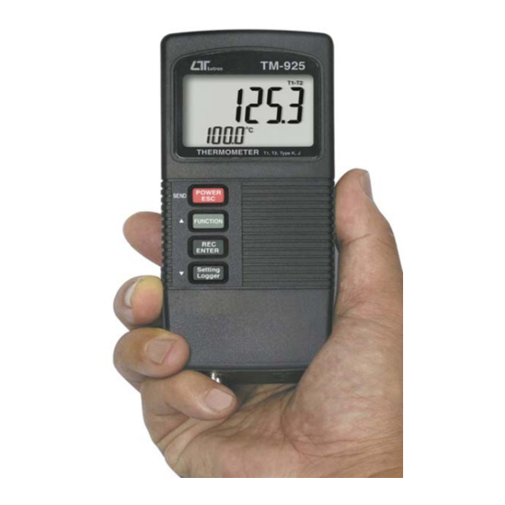
T1, T2, T1-T2, Type K/J
TWO CHANNEL
THERMOMETER
Model : TM-925
OPERATION MANUAL
Your purchase of this
THERMOMETER marks a
step forward for you
into
the
precision measurement.
A l t h o u g h
THERMOMETER
complex
and
instrument, its durable
structure
will
many years of use if
p r o p e r
o p e r a t i n g
t e c h n i q u e s
developed. Please read
t h e
f o l l o w i n g
instructions
and always keep this
manual
within
reach.
field
of
t h i s
is
a
delicate
allow
a r e
carefully
easy
Advertisement
Table of Contents

Related Manuals for Lutron Electronics TM-925


Summary of Contents for Lutron Electronics TM-925
- Page 1 T1, T2, T1-T2, Type K/J TWO CHANNEL THERMOMETER Model : TM-925 Your purchase of this THERMOMETER marks a step forward for you into field precision measurement. A l t h o u g h t h i s THERMOMETER complex...
-
Page 2: Table Of Contents
TABLE OF CONTENTS 1. FEATURES.............. 2. SPECIFICATIONS............ 3. FRONT PANEL DESCRIPTION........3-1 Display................5 3-2 Power/ESC/Send button..........5 3-3 Function/Hold button ( Send quit/ button )....▲ 3-4 REC/Enter button............5 3-5 Setting/Logger button ( button )........▼ 3-6 T1 probe socket.............. 5 3-7 T2 probe socket.............. -
Page 3: Features
1. FEATURES * Two channels thermometer, T1, T2, T1-T2, T1 only. * Both type K/J temp. measurement, wide range. / , 0.1 degree. ℃ ℉ * Microcomputer circuit provides intelligent function and high accuracy. * LCD with two display, easy readout. * Manual and auto data logger, with flexible sampling time selection, can save max. - Page 4 Display Unit ℃ ℉ Resolution , 0.1 ℃ ℉ Channels T1, T2, T1-T2, T1 only. Thermocouple Type K or Type J. type Sampling Time Manual Push the data logger button of Data Logger once will save data one time. * Se the sampling to 0 second. Auto 1, 2, 5, 10, 30, 60, 600, 1800, 3600 seconds.
- Page 5 Operating 0 to 50 ℃ Temperature Operating Less than 80% R.H. Humidity Power Supply 006P DC 9V battery ( Alkaline or Heavy duty type ). DC 9V adapter input. * AC/DC power adapter is optional. Power Current Approx. DC 5.5 mA Weight 196 g/0.43 LB.
- Page 6 2-2 Electrical Specifications (23± 5 ℃ Sensor Reso- Range Accuracy Type lution Type K 0.1 ℃ -50.0 to 1300.0 ℃ ± ( 0.4 % + 0.8 ℃ -50.1 to -199.9 ℃ ± ( 0.4 % + 1 ℃ 0.1 ℉ -58.0 to 2372.0 ℉...
-
Page 7: Front Panel Description
3. FRONT PANEL DESCRIPTION Fig. 1 3-1 Display 3-2 Power/ESC/Send button 3-3 Function/Hold button ( Send quit/ button ) ▲ 3-4 REC/Enter button 3-5 Setting/Logger button ( button ) ▼ 3-6 T1 probe socket 3-7 T2 probe socket 3-8 DC 9V adapter socket 3-9 RS-232 output terminal 3-10 Battery compartment/Cover... -
Page 8: General Measuring Procedure
4. GENERAL MEASURING PROCEDURE Meter defaults : * The temperature reading unit is ℃ * Type K measurement * Auto power off. * The sampling time of data logger function is 2 seconds. 4-1 one probe ( single channel ) measurement 1)Insert the "... -
Page 9: Two Probes ( Dual Channels ) Measurement
4-2 two probes ( dual channels ) measurement 1)For two probes ( dual channels ) measurement, insert the first " Temp. probe plug " into the " T1 probe socket " ( 3-6, Fig. 1 ) and insert the second " Temp. probe plug "... -
Page 10: Data Hold
4)Press the " Function button " ( 3-3, Fig. 1 ) continuously until the LCD show the " T1-T2 " symbol then release the finger from the button, the upper display will show the T1-T2 temperature reading, the lower display will show the T1 temperature reading. T1-T2 T1-T2 temperature ℃... -
Page 11: Data Logger
* With the " REC " symbol on the display : a) Press the " REC Button " ( 3-4, Fig. 1 ) once, the " REC MAX " symbol along with the maximum value will appear on the display. If intend to delete the maximum value, just press the "... -
Page 12: Memory Full
b)Auto Data Logger ( Sampling time should select to 1, 2, 5, 10, 30, 60, 600, 1800 or 3600 seconds ) Press the " Logger button " ( 3-5, Fig. 1 ) once to start the Data Logger function. The REC symbol will flash per sample time period and save the data into the memory. -
Page 13: Advanced Measuring Procedure
Note : 1) If intend to change the data logger sampling time, please refer section 5-4, page 12. 2) If intend to know the space of balance data numbers into the memory IC, please refer section 5-5, page 13. 3) If intend to clear the saving data from the memory please refer section 5-6, page 13. -
Page 14: Change The Type K. J
5-1 Change thermocouple type to type K or type J a. Use " button " ( 3-3, Fig. 1 ) to select " K " or " J ". ▲ b. After select the desiring value ( K or J ), press the "... -
Page 15: To Show The Balance Data Numbers In The Memory
5-5 To show the balance data numbers in the memory ( Lower display show " SPACE " ) The display will show the balance data no. that exist into the memory ( allow memorize data no. ). 5-6 Clear the existing saving data from the memory ( Lower display show "... -
Page 16: How To Send The Data Out From The Meter
6. HOW TO SEND THE DATA OUT 1)To send the data out from the meter, cancel the " Hold function " and the " Record function " first. 2)Press the " Send Button " ( 3-2, Fig. 1 ) at least 5 seconds until the lower display show "... -
Page 17: Rs232 Pc Serial Interface
7. RS232 PC SERIAL INTERFACE The instrument has RS232 PC serial interface via a 3.5 mm terminal ( 3-9, Fig. 1 ). The data output is a 16 digit stream which can be utilized for user's specific application. A RS232 lead with the following connection will be required to link the instrument with the PC serial port. - Page 18 Each digit indicates the following status : Start Word When send the upper display data = 1 When send the lower display data = 2 D12 & D11 Annunciator for Display = 01 = 02 ℃ ℉ Polarity 0 = Positive 1 = Negative Decimal Point(DP), position from right to the left 0 = No DP, 1= 1 DP, 2 = 2 DP, 3 = 3 DP...
-
Page 19: Battery Replacement
8. BATTERY REPLACEMENT 1)When the left corner of LCD display show " ", it is necessary to replace the battery. However, in-spec. measurement may still be made for several hours after low battery indicator appears before the instrument become inaccurate. 2)Slide the "... - Page 20 Data Acquisition * The SW-U801-WIN is a multi software displays ( 1/2/4/6/8 displays ) SW-U801-WIN powerful application software, provides the functions of data logging system, text display, angular display, chart display, data recorder high/low limit, data query, text report, chart report.. .xxx.mdb data file can be retrieved for EXCEL, ACESS.., wide intelligent applications.
Need help?
Do you have a question about the TM-925 and is the answer not in the manual?
Questions and answers