Page 1
Owner's / Installation Manual Important! ® 
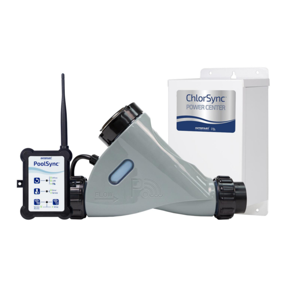
This manual covers the installation and operation of the ChlorSync Chlorine Generators. Read this manual and product labels before installing or operating this equipment. INSTALLER: THIS DOCUMENT IS PURCHASER’S PROPERTY AND IS TO REMAIN WITH THE EQUIPMENT OWNER LTP0127 REV 2.0...
Table of Contents Safety Information Safety Information General Information Contacting AquaCal AutoPilot, Inc. How Your Chlorinator Works Quick Start ChlorSync® Model Cell Options Power Center Cell Flow Bypass Kit (Optional) Patented Temperature Compensation Control Panel Overview User Display Salt Indicator LED...
Repairs must not be attempted by untrained and/or unqualified individuals. If service is deemed necessary, contact installing dealer or AquaCal AutoPilot Customer Support. RISK OF ELECTRICAL SHOCK - A bonding lug has been provided on the outside of the power center.
Page 6
NOT covered under the equipment warranty. ® For all newly constructed or resurfaced plaster pools: Do not operate the AutoPilot with newly poured or resurfaced pool plaster. Before adding salt and operating the chlorinator, wait 30 days after construction is completed to allow proper curing of the surface material.
Page 7
® While the recommended level of salt for your AutoPilot product should not damage your equipment, excessively high chlorine levels can cause corrosion damage to pool fixtures and equipment. Consult your pool professional for equipment selection, proper use and maintenance of these products.
GENERAL INFORMATION Contacting AquaCal AutoPilot, Inc. If you need to contact AquaCal AutoPilot, Inc. for questions, service, or parts, please have your model and serial numbers available. Also have the name of your installer and date of your equipment’s installation. Please refer to our website for the latest manual revisions, additional information, and helpful service advice.
® ChlorSync Model Cell Options ® The ChlorSync system consists of the following components. Part #ECP0312 Power Center- Provides power and controls communication between the power center and the cell. Three different cell options to choose from - CS30, CS40, CS50. ®...
Cell ® The cell includes buttons, a digital display, and LED indicators to control the ChlorSync ® chlorine production. See "User Display" on page 8 for more information. The ChlorSync unit measures water flow, water temperature and salt levels. If the salt level in the pool water falls below 2,300 ppm (mg/L), the unit will not produce chlorine until more salt is added to the body of water.
Flow Bypass Kit (Optional) ® The ChlorSync models are compatible with an optional flow bypass kit. The #STK0240 assembly allows the water flow rate to be slowed through the cell, while permitting the pump to continue to circulate water to-and-from the pool/spa at full flow rates. The reduced water flow through the cell results in a more efficient "Super-Chlorination”...
CONTROL PANEL OVERVIEW User Display ® ChlorSync Cell Label Figure 4 Salt Indicator LED ® The ChlorSync checks the pool water salinity on start-up and every 12 hrs. thereafter and displays the levels as follows: Green LED (solid): Indicates salt level is adequate. Pool water salt level is between 2,700 ppm (mg/L) and 4,500 ppm (mg/L).
Cell Output Control ® The ChlorSync display will show the selected sanitizer output % and cell polarity during normal △ ▽ operation. The buttons are used to adjust the sanitizer output % to the desired level. When paired with the PoolSync option, consult the PoolSync app for more information.
Page 15
Table 2 Ideal Chemical Test Effect of Low / High Levels Corrective Actions Schedule Low free chlorine: Check for combined chlorine level Low free chlorine: Not enough residual chlorine to and shock as necessary. Increase chlorine output to safely sanitize pool water. maintain a 2.0 - 4.0 ppm (mg/L) residual.
Page 16
Chlorine The desirable form of chlorine is called Free Chlorine. This form of chlorine is responsible for the actual sanitation activity in pools and spas. Free chlorine is highly reactive and, once added to pool/spa water, has a tendency to combine with organic matter in the pool/spa. It quickly attacks pathogens as well as other bather wastes.
0 ppm (mg/L). Preparing the Pool Water ® Installer please note - When properly sized to the site, the AutoPilot will meet the sanitizer “maintenance” requirements of the pool/spa. The unit is not designed to chlorine shock treat or build up a chlorine residual when starting with a zero or very low chlorine level.
Using the Saturation Index This index is used by pool professionals to ensure that your total water chemistry does not fall into a corrosive or scaling condition. Either condition can cause premature damage to the cell, any of your other equipment, as well as your cementitious finish. The Saturation Index is composed of the following factors: pH as tested Plus the Temperature factor...
Adding Salt Type of Salt to Add It is important to use Sodium Chloride (NaCl) salt that is greater than 99% pure. Acceptable types of salt include granular food grade, pool salt, water softener pellets, or solar salt flakes. Pool salt or food grade granular salt will dissolve faster than pellets or flakes. Rock salt and Granular Salt with Iodine or Rust Preventatives should not be used, as these mixtures contain high levels of impurities that may cause staining.
OPERATION Basic Operation Note: Upon initial start-up, check sanitizer every 3 - 4 days and make small output level adjustments as necessary to maintain 2.0 - 4.0 ppm (mg/L) free chlorine levels. Keep in mind, your chlorinator does not directly measure or regulate the sanitizer levels in your pool.
MAINTENANCE Cleaning the Cell ® Self Cleaning: Your AutoPilot chlorinator is designed to automatically self-clean calcium scale build up that may form on the blades during normal operation. However, unbalanced water chemistry can cause a heavy scale build up exceeding self-cleaning capabilities. Periodic manual cleaning may be necessary.
6. Fill the rest of the cell with muriatic acid, being careful not to allow solution to overflow onto the outside of the cell. This allows for an approximate 1-to-4 solution. Always add the acid to the water. If you do it the other way around, it may cause the solution to spray back, causing serious injury. If solution does spill over onto the outside of the cell, rinse with water immediately.
INSTALLATION Electrical Installation WARNING - Failure to heed the following may result in permanent injury or death. RISK OF ELECTRICAL SHOCK - Disconnect all AC power when installing or servicing this system. Follow all state, local, and National Electrical Code(s) (provincial and Canadian Electrical Code(s) if applicable).
Pool Cover Detection ® The ChlorSync can support the addition of an automatic pool cover switch (not supplied) that ® will detect when the pool cover is open or closed. The ChlorSync will automatically adjust sanitizer output when the cover is closed, avoiding over chlorination or premature cell depletion. This feature will recognize a signal from the cover switch that is a dry contact connected directly to the power center board.
Page 25
PoolSync Device Connection 1. Turn off power to the ChlorSync unit. ® 2. Remove the power center cover and the grommet in one of the available openings on the bottom of the box. 3. Insert the strain relief fitting provided with the PoolSync device.
Plumbing Installation WARNING - Failure to heed the following may result in permanent injury or death. RISK OF ELECTRICAL SHOCK - Disconnect all AC power when installing or servicing this system. Follow all state, local, and National Electrical Code(s) (provincial and Canadian Electrical Code(s) if applicable) unless local guidelines supersede.
® ChlorSync System Installation Example Figure 12 ® Connecting the ChlorSync Cell Cable to the Power Center WARNING - Failure to heed the following may result in permanent injury or death. RISK OF ELECTRICAL SHOCK - All electrical connections should be made by a licensed electrician or certified electrical contractor.
Installing the Optional Flow Bypass Kit The bypass kit can be directly plumbed into the system and must be installed so that the loop is facing upward as shown below. This orientation prevents hazardous gas buildup in the system should the flow switch fail to detect sufficient flow. The direction of the water flow through the bypass must be as indicated for the system to operate.
3. The fuse (10A) may have failed. Test and replace as necessary. 4. There may be a problem with the transformer or power supply circuit board. Contact your local service center or AquaCal AutoPilot Customer Support for assistance. Normal Display Problem There are no warning messages on the display but the chlorine level is too low.
Page 30
"Lo saLt" message is displayed / Salt LED is solid red Problem The salt level is between 2,300-2,700 ppm (mg/L), which is low. Typical Solution This message will appear when salt is between 2,300 - 2,700 ppm (mg/L). Test the salt level using salt test strips or have water tested by your local pool professional.
Page 31
Problem Possible flow switch failure. Typical Solution ® Contact your local AutoPilot service representative or AquaCal AutoPilot Customer Support. Display alternates between output percentage and a 24 hour countdown timer Problem The cell is in "Boost" mode. Typical Solution △...
SPECIFICATIONS AND APPROVALS Agency Approvals Tested to conform to the following specifications: SPECIFICATION DESCRIPTION UL1081 Safety Standard for Swimming Pool Pumps, Filters and Chlorinators. FCC Compliance NOTE: This equipment has been tested and found to comply with the limits for a Class B digital device, pursuant to part 15 of the FCC Rules.
Need help?
Do you have a question about the ChlorSync CS30 and is the answer not in the manual?
Questions and answers