Table of Contents
Advertisement
Quick Links
Owners / Installation Manual
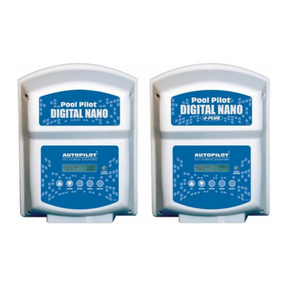
Digital Nano / Nano+
Digital Nano
Digital Nano+
Including the Optional Pool Cover Detect Switch and the 1–28 Day Surface Cure Delay
Instructions.
Important!
This manual covers the installation and operation of the Digital Nano / Nano+ Chlorine Generators.
Read this manual and product labels before installing or operating this equipment.
INSTALLER: THIS DOCUMENT IS PURCHASER'S PROPERTY AND IS TO REMAIN WITH THE EQUIPMENT OWNER
AutoPilot
Pool Pilot
Models:
Manifolds:
Cell:
Models:
Manifolds:
Cells:
®
®
75041A, 75041A-xx
PPM1, PPM1M
PPC1
75043A, 75043A-xx
PPM2, PPM2M
PPC1 or PPC2
LTP0086 REV 5
Advertisement
Table of Contents
Troubleshooting

Subscribe to Our Youtube Channel
Related Manuals for Autopilot Pool Pilot Digital Nano


Summary of Contents for Autopilot Pool Pilot Digital Nano
- Page 1 AutoPilot ® Owners / Installation Manual ® Pool Pilot Digital Nano / Nano+ Digital Nano Models: 75041A, 75041A-xx Manifolds: PPM1, PPM1M Cell: PPC1 Digital Nano+ Models: 75043A, 75043A-xx Manifolds: PPM2, PPM2M Cells: PPC1 or PPC2 Including the Optional Pool Cover Detect Switch and the 1–28 Day Surface Cure Delay Instructions.
-
Page 3: Table Of Contents
Table of Contents Section 1 - General Information 1.1 Contacting AquaCal AutoPilot, Inc. Section 2 - Safety Information 2.1 Safety Information Section 3 - Owner Quick Start & Run 3.1 How Your Chlorinator Works 3.2 Owner / Operator Control Buttons, Check System LED and Audio Alarm 3.2.a UP and DOWN Arrows... - Page 4 Section 7 - Programming 7.1 Control Panel 7.1.a Button Overview 7.1.b MENU / SELECT Button 7.1.c Display Overview 7.2 Menus 7.3 Basic Operational Programming 7.3.a Adjusting the Purifier Output % 7.3.b Boost or Super Boost 7.3.c Purifier Mode 7.3.d Purifier % Adjustment Procedure 7.4 Test Pool Pilot (Diagnostic Menu) 7.5 View Setup 7.6 Review Of Installer, Owner, &...
- Page 5 8.8 Preparing the Pool Water 8.8.a Calculating Pool Volume 8.8.b Steps to Prepare Water 8.8.c Adding Salt 8.9 Programming at Installation Section 9 - Troubleshooting 9.1 Troubleshooting 9.2 Additional Troubleshooting for Units Equipped with Optional 863A Expansion Board Section 10 - Reference 10.1 Basic Water Chemistry 10.1.a Chlorine 10.1.b pH...
-
Page 7: Section 1 - General Information
SECTION 1 - GENERAL INFORMATION 1.1 Contacting AquaCal AutoPilot, Inc. If you need to call AquaCal AutoPilot, Inc. for questions, services, or parts, please have your model and serial numbers available. Also have the name of your installer and date of your equipment’s installation. - Page 8 ® COMBUSTIBLE HAZARD – The AutoPilot chlorinator is equipped with an electronic flow switch that automatically turns the unit off in the event of a “low water flow” situation. Do not tamper in any way with this safety feature.
-
Page 9: Section 3 - Owner Quick Start & Run
For maximum cell life, maintain water in a balanced condition. Water maintained in a scaling condition ® will shorten cell life and may render the Pool Pilot inoperative. Damage and / or service calls, caused by improper water balance, will NOT be covered under the equipment warranty. Scraping or scratching the titanium blade’s edge or surface will damage the blade catalyst coating and cause premature failure of the cell... -
Page 10: Owner / Operator Control Buttons, Check System Led And Audio Alarm
3.2 Owner / Operator Control Buttons, Check System LED and Audio Alarm The following is a brief explanation of owner or operator control buttons. PLEASE NOTE: This section assumes the installer has already programmed the system for specific site parameters, has established proper water balance, and has pretreated water to 1 - 3 ppm (mg/L) chlorine. -
Page 11: Menu And Select Button
3.2.c MENU and SELECT Button The MENU button allows the operator access to the “Test Pool Pilot”, “View setup”, “Owner options”, “Maintenance” and “Installer” menus. See "Review Of Installer, Owner, & Maintenance Menu Programming" on page 21. Press the UP and DOWN arrows to scroll through the menus. The SELECT button allows the operator to choose program menu options. -
Page 12: Section 4 - Specifications And Approvals
Please note the following recommended water chemistry parameters are for residential pool / spa applications only. Follow local regulatory guidelines for any commercial pool applications. Table 1 POOL SPA Parameter Units Ideal Ideal Free Chlorine ppm mg/L 2.0 - 4.0 3.0 - 4.0 Combined Chlorine ppm mg/L... -
Page 13: Manifold Pressure Drop Vs Flow
4.2 Manifold Pressure Drop vs Flow ® The following chart shows pressure drop versus flow for all AutoPilot manifolds. ® The optional CoPilot Ozone manifold is also listed. Table 3 Table 4 4.3 Agency Approvals Tested to conform to the following specifications:... -
Page 14: Section 5 - Features
SECTION 5 - FEATURES Patented temperature compensation for chlorine output control. Programmable microprocessor control. Multi-language digital display (English, Spanish, French, German, Italian and Czech). Digitally controlled power to the cell. Tri-sensor circuitry to monitor water flow, water temperature, and salt level. Calculates and displays amount of salt needed to reach the recommended 3,000 ppm (mg/L) salt concentration level. -
Page 15: Automatic - Flow Bypass Manifold Assembly
5.2.a Automatic - Flow Bypass Manifold Assembly Models PPM1, PPM1M and PPM2, PPM2M: ® The AutoPilot manifold is connected into the plumbing after all other equipment. Water from the pool / spa is moved though the manifold by the circulation pump. The manifold uses four key components: ®... -
Page 16: Additional Features With The 863A Expansion Board Option
5.3 Additional Features with the 863A Expansion Board Option When the optional 863A Expansion Board is purchased and installed, your Digital Nano/Nano+ will be equipped with a variety of additional features. 5.3.a Automatically Reduce Chlorine Output When Pool Cover Closes Once installed, the new board will support the addition of an automatic pool cover switch (not supplied) that will detect when the pool cover is open or closed. -
Page 17: Set Purifier Off
5.3.c Set Purifier Off The Set Purifier Off feature will allow the Digital Nano/Nano+ to be programmed to delay chlorine production if salt will not be added to the pool water for a specified amount of time, from 1-28 days. Or if there is a need to halt chlorine production for a set amount of time. SECTION 6 - MAINTENANCE 6.1 Fuse Location and Ratings WARNING - Failure to heed the following may result in permanent injury or death. -
Page 18: Removing / Inspecting / Cleaning Tri-Sensor
6.2 Removing / Inspecting / Cleaning Tri-sensor 6.2.a Tri-sensor Assembly Overview The Tri-sensor Assembly is used to measure water flow, salt level, and water temperature. Note: The use of high strength magnet devices in the close proximity of the Tri-sensor can cause the flow switch to function incorrectly. -
Page 19: Cleaning Tri-Sensor / Salt Sensor
6.2.c Cleaning Tri-sensor / Salt Sensor If required, you can remove a calcium scale buildup by creating a solution of water and muriatic acid as follows. Do not use any metallic objects to scrape the blade surfaces or you will remove or damage the blade sensor coating. -
Page 20: Servicing The Cell
6.3 Servicing the Cell The cell may require removal for periodic visual inspections, or for servicing when debris or calcium mineral deposits develop. The need to inspect and service the cell is indicated by the CHECK SYSTEM light flashing and / or a screen message, “Error purify off”; “Check flow” or “Warning!”;... -
Page 21: Manual Cleaning
Scraping or scratching the titanium blade’s edge or surface will damage the blade catalyst coating and cause premature failure of the cell... warranty will be voided. Never use any sharp or metallic objects to remove scale. 1. Place a PLA0113 cell cleaning plug (AutoPilot accessory) on the end of the cell ®... -
Page 22: Winterizing
Drain all water from the manifold assembly (cell and Tri-sensor), pump, filter, supply and return lines prior to freezing weather. ® If desired, AutoPilot plug kit #996 may be purchased to cover the openings. The manifold assembly, including the cell, Tri-sensor and cables may be stored indoors. -
Page 23: Section 7 - Programming
SECTION 7 - PROGRAMMING 7.1 Control Panel 7.1.a Button Overview 7.1.b MENU / SELECT Button The MENU button is used to enter the program and diagnostic modes. Use the UP / DOWN arrows and SELECT button to navigate through the menus and sub-menus. Note: To permit quick access to features, some functions are accessed or programmed in several menus. -
Page 24: Menus
7.2 Menus Use this overview for quick reference to the menu program sequence. Some menu features will only display with specific system configurations, as noted below. Page - 18... -
Page 25: Basic Operational Programming
7.3 Basic Operational Programming 7.3.a Adjusting the Purifier Output % Typically, once the initial setting is established, very little adjustment is needed. The Purifier Output % setting refers to the amount of time the cell is energized within a 15 minute cycle. The system cycles on-and-off, as indicated on the display's lower right display and “On,”... -
Page 26: Purifier % Adjustment Procedure
7.3.d Purifier % Adjustment Procedure 1. Balance water chemistry according to necessary water chemistry parameters. See "Basic Water Chemistry" on page 43. For new start ups, if free chlorine level as tested is not at least 1 ppm (mg/L), add liquid chlorine to ensure 1 to 3 ppm (mg/L) free chlorine reading. 2. -
Page 27: View Setup
7.5 View Setup A program and parameter menu used to view the currently programmed settings. Press the MENU button, then press UP or DOWN arrow until “View Set Up” is displayed and press the SELECT button. The display will automatically sequence through the following displays and then return to normal operation. -
Page 28: Select Language
7.6.c Select Language Allow for personal preference language display. △ ▽ 1. Press MENU, press until “Owner options” or “Installer menu” is displayed, then press SELECT. △ ▽ 2. Press until “Select language” is displayed, then press SELECT (English is the factory setting). -
Page 29: Display Temperature
7.6.g Display Temperature Choose to either show or hide the water temperature on the normal display screen. △ ▽ 1. Press MENU, press until “Installer menu” is displayed, then press and hold SELECT (approximately 13 seconds) until “Installer menu” is displayed again and is accessible. △... -
Page 30: Menu Programming-Optional 863A Expansion Board Features
7.7 Menu Programming-Optional 863A Expansion Board Features 7.7.a Display time Choose to either show or hide the time on the normal display screen. △ ▽ 1. Press MENU, press or until “Installer menu” is displayed, then press and hold SELECT (approximately 13 seconds) until “Installer menu”... -
Page 31: Set Purifier Off
7.7.e Set Purifier Off The Digital Nano / Nano+ system can be programmed to delay chlorine production if salt will not be added to the pool water for a specified amount of time, from 1-28 days. The system will automatically start up in the Purifier mode after the user defined time has expired. This feature can be used when starting up a newly constructed or resurfaced pool when salt is not going to be added for a few days. -
Page 32: Section 8 - Installation
SECTION 8 - INSTALLATION 8.1 Basic System Overview The Digital Nano / Nano+ is a salt chlorination system for pool or spa purification, and is designed to operate in the following configurations: Shown with automatic-flow bypass manifold assembly (models PPM1 and PPM2): Figure 11 ®... -
Page 33: Planning The Installation
8.2 Planning the Installation ® Before installing your Pool Pilot 1. Determine everything needed for installation is on hand. 2. Determine where the Manifold Assembly will be plumbed. 3. Identify a suitable mounting location for the Pool Pilot ® close enough, less than 12’ (3.6 m), to ensure that the cell cord and Tri-sensor cord will reach the manifold components. -
Page 34: Plumbing The System
3. Plumbing the System ( See "Plumbing The System" on page 28. ) 4. Preparing the Water ( See "Preparing the Pool Water" on page 34. ) 5. Programming at Installation ( See "Programming at Installation" on page 36. ) 8.5 Plumbing The System The Manifold Assembly has 2"... -
Page 35: Mounting The Chlorinator
8.6 Mounting the Chlorinator ATTENTION: To ensure adequate cable length, we recommend plumbing the manifold first and then mounting the control unit close enough so that the cables will reach. The Tri-sensor and cell cables are 12’ (3.6 m) long. The selected location should allow easy access for service and maintenance. -
Page 36: Ac Input Voltage
4. Install the fuse labeled FUSE: 2A 250V 3AG SLO BLO into the fuse clip on the power supply board as shown in the photo below. *Note: If a 110V cord is needed, you can order the AutoPilot Power Cord Kit #STK0196. You may also obtain a 16 AWG 2 conductor w / ground power cord, suitable for outdoor applications, from your local hardware or electrical supply store. -
Page 37: Low Voltage Wiring
8.7.c Low Voltage Wiring WARNING - Failure to heed the following may result in permanent injury or death. ELECTRICAL SHOCK HAZARD – Turn off the electrical power to unit before servicing. Connecting the Cell Cable 1. The cell cable connector is keyed and must be aligned to connect properly. Line up the cell cord and ®... - Page 38 Figure 20 Figure 21 Figure 22 Figure 23 Figure 24 Page - 32...
-
Page 39: Connecting The Retractable Cover Switch (Option Only Available With Purchase Of #863A Expansion Board)
8.7.e Connecting the Retractable Cover Switch (Option only available with purchase of #863A Expansion Board) CAUTION - Failure to heed the following may result in equipment damage. The cover switch input must connect to an isolated dry contact output from the retractable cover unit. Connection to an energized switch will damage the Digital Nano / Nano+. -
Page 40: Preparing The Pool Water
8.8 Preparing the Pool Water ® Installer please note - When properly sized to the site, the Pool Pilot will meet the sanitizer ® “maintenance” requirements of the pool / spa. The Pool Pilot is not designed to chlorine shock treat, or build up a chlorine residual, when starting with a zero or very low chlorine level. -
Page 41: Adding Salt
8.8.c Adding Salt Type of Salt to Add It is important to use Sodium Chloride (NaCl) salt that is greater than 99% pure. Acceptable types of salt include granular food grade, pool salt, water softener pellets, or solar salt flakes; these are usually available in 25 to 60 lb bags (11 to 27 kg) at local pool or building supply outlets. -
Page 42: Programming At Installation
8.9 Programming at Installation The Digital Nano / Nano+ requires the pool volume be programmed into the installer menu. The Digital Nano / Nano+ will then indicate how many pounds (kgs) of salt to add should salt levels fall. 1. Enter the “Installer menu” and program "Set pool volume" for specific pool. See "Calculating Pool Volume"... - Page 43 4. Check and clean the skimmer basket. 5. Check and clean the pump basket. 6. Check and clean or backwash the main circulation filter. 7. Clean the AutoPilot manifold screen of trash or debris. For instructions to clean the screen, test the ®...
- Page 44 65 °F (18.3 °C), a scaled cell, or cell near end of life. Correct as appropriate. If the volts are less than 20, then contact AquaCal AutoPilot, Inc. for assistance. 2. Installer: If the unit is configured for 230 Vac operation, then verify the input AC voltage is not 115 Vac.
- Page 45 65 °F (18.3 °C), a scaled cell, or cell near end of life. Correct as appropriate. If the volts are less than 20, then contact AquaCal AutoPilot, Inc. for assistance. 2. Installer: If the unit is configured for 230 Vac operation, then verify the input AC voltage is not 115 Vac.
- Page 46 Typical Solution 1. Check the Tri-sensor cable; make sure it is not disconnected or loose. 2. Check the water temperature. If confirmed temperature is OK, contact AquaCal AutoPilot, Inc. for assistance. Warning! Low Amps: Cell? Warning! Low cell volts Warning! No output (All three...
- Page 47 Cooling Problem Unit is not generating chlorine. Typical Solution Internal temperature of unit has exceeded “Shutoff temp”, viewable in Setup Menu. Will turn off chlorine generation for five (5) minutes or until temperature decreases. If this is not causing a chlorine shortage, let the unit automatically cool and resume normal operation.
- Page 48 Problem Chlorine % fluctuates from adjusted value. Typical Solution The AutoPilot unit has a patented process for automatically increasing and reducing the ® chlorine output as the temperature of the water fluctuates. It is normal for the % output to increase as the water temperature increases, and to decrease as the water temperature decreases.
-
Page 49: Additional Troubleshooting For Units Equipped With Optional 863A Expansion Board
9.2 Additional Troubleshooting for Units Equipped with Optional 863A Expansion Board Normal Display Problem Cover is closed. “Cover closed” is not displayed. Chlorine production too high. Cover is open. "Cover closed" is displayed. Typical Solution 1. Confirm the installed Pool Pilot ®... - Page 50 Ideal Chemical Test Effect of Low / High Levels Corrective Actions Schedule Low free chlorine: Check for combined chlorine level Low free chlorine: Not enough residual chlorine to and shock as necessary. Increase chlorine output to safely sanitize pool water. maintain a 1-3 ppm (mg/L) residual.
-
Page 51: Chlorine
10.1.a Chlorine The desirable form of chlorine is called Free Chlorine. This form of chlorine is responsible for the actual sanitation activity in pools and spas. Free chlorine is highly reactive and, once added to pool / spa water, has a tendency to combine with organic matter in the pool /spa. It quickly attacks pathogens as well as other bather wastes. -
Page 52: Using The Saturation Index
10.2 Using the Saturation Index This index is used by pool professionals to ensure that your total water chemistry does not fall into a corrosive or scaling condition. Either condition can cause premature damage to the cell, any of your other equipment, as well as your cementitious finish. The Saturation Index is composed of the following factors: pH as tested Plus the Temperature factor... -
Page 53: Salt Addition Chart
10.3 Salt Addition Chart The following salt charts are included for reference only; once programmed to the correct water volume, the controller will automatically indicate how much salt is required to achieve optimum water salinity. The salt in the pool is constantly recycled during normal operation. Loss of salt during a swimming season should be minimal. -
Page 54: Section 11 - Fcc Compliance
SECTION 11 - FCC COMPLIANCE 11.1 FCC Compliance NOTE: This equipment has been tested and found to comply with the limits for a Class B digital device, pursuant to part 15 of the FCC Rules. These limits are designed to provide reasonable protection against harmful interference in a residential installation. - Page 56 AquaCal AutoPilot, Inc. 2737 24 Street North St. Petersburg, Florida 33713 (727) 823-5642...
Need help?
Do you have a question about the Pool Pilot Digital Nano and is the answer not in the manual?
Questions and answers