Table of Contents
Advertisement
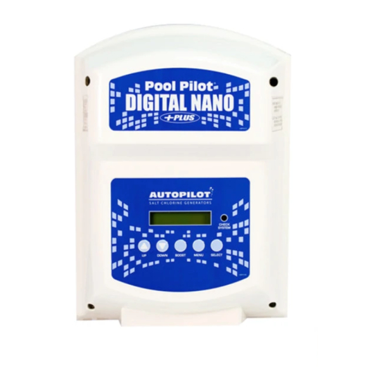
Digital Nano/Nano+
Digital Nano
Digital Nano +
Owner's Manual: Installation / Operation
This manual covers the installation and operation of the Digital Nano/Nano+ Chlorine Generators
Important!
Read This Manual and Product Labels Before Installing or Operating This Equipment
INSTALLER: THIS DOCUMENT IS PURCHASER'S PROPERTY AND IS TO REMAIN WITH THE EQUIPMENT OWNER
Pool Pilot
Models:
75041A, 75041A-xx
Manifolds:
PPM1, PPM1M
Cell:
PPC1
Models:
75043A, 75043A-xx
Manifolds:
PPM2, PPM2M
Cells:
PPC1 or PPC2
®
LTP0086 Rev4 05/11/2017
Advertisement
Table of Contents

Related Manuals for Autopilot Pool Pilot Digital Nano+


Summary of Contents for Autopilot Pool Pilot Digital Nano+
- Page 1 Pool Pilot ® Digital Nano/Nano+ Digital Nano Models: 75041A, 75041A-xx Manifolds: PPM1, PPM1M Cell: PPC1 Digital Nano + Models: 75043A, 75043A-xx Manifolds: PPM2, PPM2M Cells: PPC1 or PPC2 Owner’s Manual: Installation / Operation This manual covers the installation and operation of the Digital Nano/Nano+ Chlorine Generators Important! Read This Manual and Product Labels Before Installing or Operating This Equipment INSTALLER: THIS DOCUMENT IS PURCHASER’S PROPERTY AND IS TO REMAIN WITH THE EQUIPMENT OWNER...
-
Page 3: Table Of Contents
Page i TABLE OF CONTENTS SECTION 1 - FACTORY CONTACT INFORMATION................... 1 SECTION 2 - SAFETY INFORMATION ........................ 1 SECTION 3 - OWNER QUICK START & RUN ..................... 4 3.1 How Your Digital Nano/Nano+ Works ......................4 3.2 Optional 863A Expansion Board Additional Features ..................4 3.3 Owner/Operator Control Buttons, CHECK SYSTEM LED, and Audio Alarm .......... - Page 4 Page ii TABLE OF CONTENTS 7.3.3 Chlorine Mode ..........................21 7.3.4 Chlorine % Adjustment Procedure ..................... 21 7.4 Test Pool Pilot (Diagnostic Menu) ........................ 22 7.5 View Setup ..............................22 7.6 Review of Installer, Owner, & Maintenance Menu Programming ..............23 7.6.1 Set Pool Volume .........................
- Page 5 Page iii TABLE OF CONTENTS 10.3 Salt Addition Chart ............................52 10.4 Declaration of Conformity ........................... 53 10.5 FCC Compliance ............................53...
-
Page 7: Section 1 - Factory Contact Information
SECTION 1 - FACTORY CONTACT INFORMATION If you should need to call AquaCal AutoPilot, Inc. for questions, services, or parts, please have your model and serial numbers available. Please also have the name of your installer and date of your equipment’s installation. - Page 8 Maintain Pool / Spa water per standards detailed later in this manual. COMBUSTIBLE HAZARD – The AutoPilot ® Digital Nano/Nano+ is equipped with an electronic flow switch that automatically turns the unit off in the event of a “low water flow”...
- Page 9 Page 3 Excessively high chlorine levels can cause corrosion damage to pool fixtures and equipment. For maximum cell life, maintain water in a balanced condition. Water maintained in a scaling condition will shorten cell life and may render the Digital Nano/Nano+ inoperative.
-
Page 10: Section 3 - Owner Quick Start & Run
Page 4 SECTION 3 - OWNER QUICK START & RUN 1) Balance the water chemistry according to the water chemistry parameters on page 7 and salt recommendations on page 37. The Digital Nano/Nano+ may be started immediately. The salt reading, however, may initially be inaccurate until the circulation pump has been run for 24 hours to fully dissolve newly added salt. -
Page 11: Owner/Operator Control Buttons, Check System Led, And Audio Alarm
Page 5 3.3 OWNER/OPERATOR CONTROL BUTTONS, CHECK SYSTEM LED, AND AUDIO ALARM The following is a brief explanation of owner or operator control buttons. Please Note: This section assumes the installer has already programmed the system for specific site parameters, has established proper water balance, and has pretreated water to 1 - 3 ppm (mg/L) chlorine. -
Page 12: Check System Light And Audio Alarm
Page 6 3.3.4 CHECK SYSTEM Light and Audio Alarm The CHECK SYSTEM light will flash to warn the unit may need attention. A warning message will also be displayed. If enabled, an audio alarm* may also be heard when the system light is flashing. -
Page 13: Water Balance And Chemistry Recommendations
Page 7 3.5 WATER BALANCE AND CHEMISTRY RECOMMENDATIONS Water balance is not complicated. It is the relationship between different chemical measurements in your pool water. A pool that is balanced has proper levels of pH, Total Alkalinity and Calcium Hardness. Balanced water can also be defined as water that is not corrosive or scaling. -
Page 14: Specification And Approvals
Page 8 SECTION 4 - SPECIFICATION AND APPROVALS 4.1 SPECIFICATIONS SPECIFICATION 75041A, 75041A, 75043A, 75043A, 75041-XX 75041A-XX 75043A-XX 75043A-XX (when converted (when converted to 110V-120V in to 110V-120V in the field) the field) 110-120 Vac 220-240 Vac 110-120 Vac 220-240 Vac Input Power: 2.0 A 1.0 A... -
Page 15: Manifold Pressure Drop Versus Flow
Page 9 4.2 MANIFOLD PRESSURE DROP VERSUS FLOW The following chart shows pressure drop versus flow for all Digital Nano/Nano+ manifolds. The optional ® CoPilot Ozone manifold is also listed. Table 3 ® PPMxx & CoPilot Ozone Standard (941xx) PPMxx CoPilot Ozone ®... -
Page 16: Section 5 - Features
Page 10 SECTION 5 - FEATURES Patented temperature compensation for chlorine output control. Programmable microprocessor control. Multi-language digital display (English, Spanish, French, German, Italian and Czech). Digitally controlled power to the cell. Tri-sensor circuitry to monitor water flow, water temperature, and salt level. ... -
Page 17: Automatic-Flow Bypass Manifold Assembly (Models Ppm1, Ppm1M And Ppm2, Ppm2M)
5.2.1 Automatic-Flow Bypass Manifold Assembly (models PPM1, PPM1M and PPM2, PPM2M) ® Tri-sensor The AutoPilot patented manifold is connected into the plumbing after all other equipment. Water from the pool/spa is moved though the manifold by the circulation pump. The manifold uses four key... -
Page 18: Automatically Reduce Chlorine Output When Pool Cover Closes
Page 12 5.3 AUTOMATICALLY REDUCE CHLORINE OUTPUT WHEN POOL COVER CLOSES When the pool cover is closed, the Digital Nano/Nano+ will automatically reduce the chlorine output to 20% of the normal open cover setting. This only applies to models that are equipped with the optional 863A Expansion Board and the cover position switch is connected to the unit. -
Page 19: Removing / Inspecting / Cleaning Tri-Sensor
Page 13 6.2 REMOVING / INSPECTING / CLEANING TRI-SENSOR 6.2.1 Tri-sensor Assembly Overview The Tri-sensor Assembly is used to measure water flow, salt level, and water temperature. Note: The use of high strength magnet devices in the close proximity of the Tri-sensor can cause the flow switch to function incorrectly. -
Page 20: Cleaning Tri-Sensor/Salt Sensor
Page 14 7) Do not use any metallic objects to scrape the blade surfaces or you will remove or damage the blade sensor coating. 6.2.3 Cleaning Tri-sensor/Salt Sensor If required, you can remove a calcium scale buildup by creating a solution of water and muriatic acid as follows. -
Page 21: Servicing The Cell
Page 15 6) Wrap the strainer screen securely with a small piece of plastic wrap (saran wrap, food wrap or zip lock bag) as indicated in the diagram, place it back in the union. 7) Tighten the two unions that were loosened. Do not over tighten. 8) Turn on the pump and the Digital Nano/Nano+. -
Page 22: Visual Inspection
Never use any sharp or metallic objects to remove scale. ® 1) Place a PLA0113 cell cleaning plug (AutoPilot accessory) on the end of the cell as shown. A 1 ½” MPT clean out plug may also be used and can be purchased in the PVC plumbing section at most pool supply or home improvement stores. -
Page 23: Winterizing
Page 17 CAUTION: Failure to heed the following may result in equipment damage. The electrical terminals must be completely dry to avoid corrosion and failure of the cell or cable. 1) Clean and dry the electrical pins on the cell. The contacts must be completely dry to avoid corrosion and failure of the cell or cable. -
Page 24: Section 7 - Programming
Page 18 SECTION 7 - PROGRAMMING 7.1 CONTROL PANEL 7.1.1 Button Overview CHECK SYSTEM LIGHT: Push UP or DOWN arrow to Red LED flashes to warn do the following: Sets Chlorine Level % attention is required A warning message will ... -
Page 25: Menus
Page 19 7.2 MENUS Use this overview for quick reference to the menu program sequence. Some menu features will only display with specific System Configurations, as noted below. 1- Protected Access (This only applies to models that are equipped with the optional 863A Expansion Board.) Main Menu Test Pool Pilot... -
Page 26: Basic Operational Programming
Page 20 7.3 BASIC OPERATIONAL PROGRAMMING 7.3.1 Adjusting the Chlorine Output % Typically, once the initial setting is established, very little adjustment is needed. The chlorine % setting refers to the amount of time the cell is energized within a 15 minute cycle. The system cycles on-and-off, as indicated on the display's lower right display and “On,”... -
Page 27: Chlorine Mode
Page 21 Caution: Regardless of retractable pool cover position, when the Boost feature is activated the unit will increase chlorine production to 100% for 24 or 72 hours based on the Boost time selected. To exit Boost or Super Boost mode and revert to normal operation: ... -
Page 28: Test Pool Pilot (Diagnostic Menu)
Page 22 7.4 TEST POOL PILOT (DIAGNOSTIC MENU) Press the MENU button, then press the UP or DOWN arrow until “Test Pool Pilot” is displayed, and press the SELECT button. The display will automatically sequence through the following displays and then return to normal operation. You can also press the UP or DOWN arrow to scroll forwards and backwards. -
Page 29: Review Of Installer, Owner, & Maintenance Menu Programming
Page 23 7.6 REVIEW OF INSTALLER, OWNER, & MAINTENANCE MENU PROGRAMMING Note: Once determined to be appropriately programmed for the installation site, the following menu items should not require regular access. See “Basic Operational Programming” on page 20 for setting the initial Chlorine Level and routine control instructions. -
Page 30: Select Units
Page 24 7.6.5 Select Units Used to program the operator’s personal preferences for the liquid and weight measurements the Digital Nano/Nano+ will display. until “Owner options” or “Installer menu” is 1) Press MENU, press displayed; then press SELECT. until “Select units” is displayed; then press SELECT (“English 2) Press units”... -
Page 31: Set Time Of Day (Optional Feature W/ 863A Expansion Board)
Page 25 7.6.9 Set Time of Day (Optional Feature w/ 863A Expansion Board) Change the time of day display to correct for time zone or Daylight Saving. until “Owner options”, “Maintenance Menu” or 1) Press MENU, press “Installer Menu” is displayed, then press SELECT. until “Set time of day”... -
Page 32: Force Reverse
Page 26 3) Press until the desired cycle time (2, 4, 8, or 16 hours) is displayed; then press SELECT. until “End menu mode” is displayed; then press SELECT. 4) Press 7.6.12 Force Reverse Note: This is a diagnostic tool only, and should not be used unless a problem is suspected. Program the cell to activate a Force Reverse cycle and verify if the system is reversing polarity (self-cleaning). -
Page 33: Section 8 - Installation
Page 27 SECTION 8 - INSTALLATION 8.1 BASIC SYSTEM OVERVIEW The Digital Nano/Nano+ is a salt chlorination system for pool or spa purification, and is designed to operate in the following configurations: SHOWN WITH AUTOMATIC-FLOW BYPASS MANIFOLD ASSEMBLY (models PPM1 or PPM2): Figure 10 ®... -
Page 34: Plannning The Installation
Page 28 8.2 PLANNNING THE INSTALLATION 8.2.1 Before installing the Digital Nano/Nano+: 1) Determine everything needed for installation is on hand. 2) Determine where the Manifold Assembly will be plumbed. 3) Identify a suitable mounting location for the Digital Nano/Nano+ close enough, less than 12’ (3.6 m), to ensure that the cell cord and Tri-sensor cord will reach the manifold components. -
Page 35: Installation Steps
Page 29 8.4 INSTALLATION STEPS Details on each step of the installation process are presented on the following pages: 1) Mounting the Digital Nano/Nano+ 2) Electrical Connections (page 30) Electrical Connections Overview AC Input Voltage Low Voltage Wiring ... -
Page 36: Electrical Connections
4) Install the fuse labeled FUSE: 2A 250V 3AG SLO BLO into the fuse clip on the power supply board as shown in the photo below. *Note: If a 110V cord is needed, you can order the AutoPilot Power Cord Kit #STK0196. You may also obtain a 16 AWG 2 conductor w/ground power cord, suitable for outdoor applications, from your local hardware or electrical supply store. -
Page 37: Ac Input Voltage
Page 31 8.6.2 AC Input Voltage WARNING: Failure to heed the following may result in injury or death. The Digital Nano/Nano+ control center supply circuit must be protected by a ground- fault circuit- interrupter (GFCI). CAUTION: Failure to heed the following may result in equipment damage. The AC input cannot be provided by an ORP Controller. - Page 38 Page 32 Connecting the Retractable Cover Switch (Option only available with purchase of #863A Expansion Board) CAUTION: Failure to heed the following may result in equipment damage. The cover switch input must connect to an isolated dry contact output from the retractable cover unit.
- Page 39 Page 33 Figure 14 Figure 15 Figure 16 Figure 17 863A (Optional) 863A (Optional) B=Black R=Red Y=Yellow W=White Split Gland Figure 19 Figure 20 Figure 18...
-
Page 40: Bonding
Page 34 14) Thread the cover switch cable, provided by installer, through the gland as shown in Figure 21, below. 15) Connect the (2) conductors of the cable to the terminal labeled COVER CONTACT on the bottom right side of the 863A Expansion Board. See Figure 22. 16) Reattach the RJ11 modular cable at J2 on the display board, previously released in step 3, back to the J1 position on the main board. -
Page 41: Plumbing The System
Page 35 8.7 PLUMBING THE SYSTEM The Manifold Assembly has 2" PVC Slip Socket connections. Metric PVC adapters, 2” spigot x 63 mm socket, are provided with metric manifold models that have an “M” suffix, such as PPMxM. The manifold is plumbed into the pool return line after the heater and spa diverter valve, if applicable. See Figure 10 and Figure 11 on page 27 for typical installations. -
Page 42: Preparing The Pool Water
Page 36 8.8 PREPARING THE POOL WATER Installer please note - When properly sized to the site, the Digital Nano/Nano+ will meet the sanitizer “maintenance” requirements of the pool/spa. The Digital Nano/Nano+ is not designed to chlorine shock treat, or build up a chlorine residual, when starting with a zero or very low chlorine level. Before starting the Digital Nano/Nano+, the water must be properly balanced, and the chlorine level must be adjusted to between 1 to 3 ppm (mg/L) free chlorine. -
Page 43: Adding Salt
Page 37 8.8.3 Adding Salt Type of Salt to Add It is important to use Sodium Chloride (NaCl) salt that is greater than 99% pure. Acceptable types of salt include granular food grade, pool salt, water softener pellets, or solar salt flakes;... -
Page 44: Programming At Installation
Page 38 8.9 PROGRAMMING AT INSTALLATION The Digital Nano/Nano+ requires the pool volume be initially programmed into the installer menu. The Digital Nano/Nano+ will then indicate how many pounds (kgs) of salt to add should salt levels fall. The default pool size is 15,000 gallons (60,000 liters). The Salt Addition Chart on page 52 can also be used to calculate how much salt in pounds (kgs) should be added to reach the recommended level of 3,000- 4,000 ppm (mg/L) salinity. -
Page 45: Language Translation Matrix
Page 39 8.10 LANGUAGE TRANSLATION MATRIX English Francais Italiana Español Deutsche Cesky 000 gallons 000 gallons 000 galloni 000 galones 000 Gallonen 000 Galon 000 liters 000 litres 000 litri 000 litros 000 Liter 000 Litr 1 minute 1 minute 1 minuto 1 minuto 1 Minute... - Page 46 Page 40 English Francais Italiana Español Deutsche Cesky hour on HeureOn ore sopra Hora on Zeitein Cas On Installer menu Menu install. MenuInstalazione Menú instalación Install. Menü Instalacni menu Bas. Bajo ger. Nizke Low Amps: Cell? Amps bas - cell? Basso Amp-Cella? Bajo Amperaje? A.niedrig-Zelle?
- Page 47 Page 41 English Francais Italiana Español Deutsche Cesky English Francais Italiana Español Deutsche Cesky Show temperature Montrer temp. Mostrare temp. Ver temp. Temp zeigen Zobrazit ║C Show time Montrer time Mostrare time Ver hora Time zeigen Zobrazit time Software Logiciel Software Software Software...
-
Page 48: Section 9 - Troubleshooting
Page 42 SECTION 9 - TROUBLESHOOTING MESSAGE DISPLAYED PROBLEM TYPICAL SOLUTION Cell inspect due This is an advisory The cell has been operating for a while. This is a message. reminder that now would be a good time to remove and inspect the cell and filter screen to see if they need The unit will generate cleaning. - Page 49 Water Chemistry related problem (See Reference section of manual, Water Chemistry and Saturation Index topics). The Digital Nano/Nano+ may not be reversing polarity – contact your local AutoPilot Service Center. Adjust water chemistry or adjust Set Reverse time to a shorter cycle.
- Page 50 Digital Nano/Nano+ All 3 messages must be displayed for this to be a messages are being displayed.) control unit problem. control unit problem. Contact AquaCal AutoPilot, Inc. for service. Warning! If all 3 messages are not being displayed then refer Low Amps: Cell? to the specific individual fault message above.
- Page 51 Page 45 MESSAGE DISPLAYED PROBLEM TYPICAL SOLUTION Normal display There are no warning The chlorine setting has been fine, but a temporary messages on the boost of chlorine is needed to adjust for rain or a display but the temporary bather increase. Press the BOOST button chlorine level is too to temporarily elevate the chlorine production level to low.
- Page 52 If cover is open, then check the external dry contact cover position switch & cable for proper operation. ® Chlorine % fluctuates The AutoPilot unit has a patented process for from adjusted value. automatically increasing and reducing the chlorine output as the temperature of the water fluctuates. It is...
- Page 53 Page 47 MESSAGE DISPLAYED PROBLEM TYPICAL SOLUTION Cooling Internal temperature of unit has exceeded “Shutoff Unit is not generating temp”, viewable in Setup Menu. Will turn off chlorine Chlorine. generation for five (5) minutes or until temperature decreases. If this is not causing a chlorine shortage, let the unit automatically cool and resume normal operation.
-
Page 54: Section 10 - Reference
Page 48 SECTION 10 - REFERENCE 10.1 BASIC WATER CHEMISTRY The Digital Nano/Nano+ is designed to produce chlorine on a daily basis. To monitor the system’s efficiency, the water chemistry ranges, and schedule of periodic checks should be followed. See “Water Balance and Chemistry Recommendations”... - Page 55 Page 49 IDEAL EFFECT OF CHEMICAL TEST CORRECTIVE ACTIONS LOW / HIGH LEVELS SCHEDULE Calcium Monthly Low CH: Etching of plaster, equipment Low CH: Add calcium chloride flakes. Hardness corrosion High CH: Scale formation, cloudy water. High CH: Partially drain and refill pool with Rapid buildup of scale may exceed the fresh water to dilute.
-
Page 56: Chlorine
Page 50 10.1.1 Chlorine The desirable form of chlorine is called Free Chlorine. This form of chlorine is responsible for the actual sanitation activity in pools and spas. Free chlorine is highly reactive and, once added to pool/spa water, has a tendency to combine with organic matter in the pool/spa. It quickly attacks pathogens as well as other bather wastes. -
Page 57: Using The Saturation Index
Page 51 10.2 USING THE SATURATION INDEX This index is used by pool professionals to ensure that your total water chemistry does not fall into a corrosive or scaling condition. Either condition can cause premature damage to the cell, any of your other equipment, as well as your cementitious finish. -
Page 58: Salt Addition Chart
Page 52 10.3 SALT ADDITION CHART The following salt charts are included for reference only; once programmed to the correct water volume, the controller will automatically indicate how much salt is required to achieve optimum water salinity. The salt in the pool is constantly recycled during normal operation. Loss of salt during a swimming season should be minimal. -
Page 59: Declaration Of Conformity
Page 53 10.4 DECLARATION OF CONFORMITY 10.5 FCC COMPLIANCE NOTE: This equipment has been tested and found to comply with the limits for a Class B digital device, pursuant to part 15 of the FCC Rules. These limits are designed to provide reasonable protection against harmful interference in a residential installation. - Page 60 AquaCal AutoPilot, Inc. 2737 24 Street North St. Petersburg, Florida 33713 (727) 823-5642...
Need help?
Do you have a question about the Pool Pilot Digital Nano+ and is the answer not in the manual?
Questions and answers