Advertisement
Quick Links
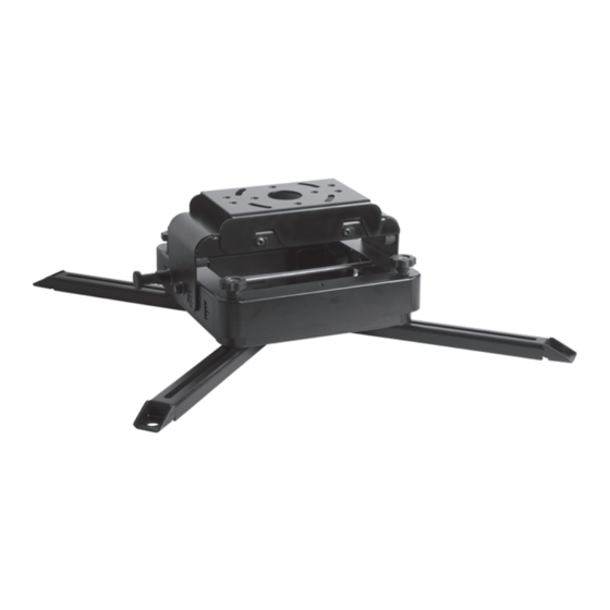
BT893
HEAVY DUTY PROJECTOR CEILING MOUNT
WITH MICRO-ADJUSTMENT
INSTALLATION GUIDE & PARTS LIST
This Pack Contains 1 Mount
PLEASE KEEP THIS FOR FUTURE REFERENCE
Installation Safety Notes.....................................................................................................................2
Parts List.............................................................................................................................................4
Installation Instructions.......................................................................................................................6
Portrait Mounting............................................................................................................... ...............13
Typical Pole Installations..................................................................................................................14
Product Dimensions..........................................................................................................................14
B-Tech Contact Details.....................................................................................................................16
INSTALLATION TOOLS REQUIRED
FEATURES
• Heavy duty ceiling mount for projectors up to 70kg (154lbs)
• Can be mounted direct to ceiling or onto Ø50mm
extension poles
• +20°/-10° Tilt (Pitch) incremented adjustment
+/-5° Additional Tilt (Pitch) micro-adjustment
+/-5° Roll micro-adjustment
25° Yaw adjustment (ceiling mounted)
45° Yaw adjustment (pole mounted)
• Extendable mounting plate features 4-point micro-adjustment
for perfect alignment of projected images
• Micro-adjustment is altered using handwheels for better
grip and more controlled adjustment
• Optional extension legs can be used to accommodate
larger fixing patterns
• Can mount projector upright for portrait or vertical projections
• Max. distance between projector fixings: 873mm
• Suitable for projectors using M6, M8, M10 and M12 fixings
• Ideal for use with projection mapping projectors
• Quick and easy assembly
70kg
CONTENTS
Drill
B-TECH AV MOUNTS
www.btechavmounts.com
5˚
15˚
25˚
5˚
Pencil
COMPATIBLE
25°
45°
POLE MOUNTED
Advertisement

Related Manuals for B-Tech BT893


Summary of Contents for B-Tech BT893
-
Page 1: Table Of Contents
• Quick and easy assembly 5˚ 15˚ 70kg 25˚ 5˚ 25° 45° POLE MOUNTED CONTENTS Installation Safety Notes........................2 Parts List.............................4 Installation Instructions........................6 Portrait Mounting..........................13 Typical Pole Installations........................14 Product Dimensions..........................14 B-Tech Contact Details........................16 INSTALLATION TOOLS REQUIRED Pencil Drill B-TECH AV MOUNTS www.btechavmounts.com... -
Page 4: Parts List
BT893 PARTS LIST Suitable for loads up to 70kg... - Page 5 PART NAME PROJECTOR MOUNT CEILING MOUNT POLE MOUNT LONG LEG SHORT LEG M8 x 12mm SCREW M8 WASHER M8 x 60mm SCREW SQUARE NUT 4mm HEX KEY 5mm HEX KEY 6mm HEX KEY 8mm HEX KEY INTERFACE KIT M6 x 16mm SCREW M6 x 30mm SCREW M8 x 16mm SCREW M8 x 30mm SCREW...
-
Page 6: Installation Instructions
INSTALLATION INSTRUCTIONS Fix Ceiling Mount in Place Directly to ceiling. Fix item 2 directly to the ceiling using suitable fixings (not supplied). Holes should be drilled into the ceiling at these positions to allow for 25° yaw adjustment. Optional depending on Ceiling Mount slots allow for adjustment type of ceiling as shown. - Page 7 Using a pole mount. i) Fix item 2 to item 3 using items 6 & 7. To use yaw adjustment on the pole mount, loosen 4 x item 6 by 1 turn. Ensure screws are tightened fully after adjustment has been made. WARNING loosened only ii) Insert a BT7850 Ø50mm pole (sold separately) into item 3 and secure in place with item 8.
- Page 8 Attach Projector Mount to Projector A. Without legs (up to 200 x 200mm fixing centres). Attach item 1 directly to the projector using items A - D & I - J with items 10 -13. Fix mount by using suitable holes and / or slots on the bottom of the projector mount. Arrow indicates PROJECTOR front of mount...
- Page 9 B. Using legs Attach items 4 / 5 to item 1 using items 6 & 9. Fix items 4 / 5 to the projector using items A - O. Note: Where possible, use Note: Where possible, use all fixing holes on projector 2 x item 6 and 2 x item 9 (4 minimum).
- Page 10 Hook Projector Mount onto Ceiling Mount Hook the 4 M8 x 12mm screws (attached to item 1) into CEILING the 4 hook-in slots on item 2. Fully tighten all 4 screws once hooked on. Use gap to hook onto item 2. M8 x 12mm SCREW (Do not...
- Page 11 B. Micro-adjust the projector tilt / roll angle (+/-5° tilt / +/-5° roll). Turn handwheels clockwise to raise, or anti-clockwise to lower projector. Arrow indicates front of mount HANDWHEEL PROJECTOR i) Micro-adjust the tilt using either the front 2, or back 2 handwheels simultaneously (+/-5° tilt). Micro-adjustment tilt / roll guidelines are located on the...
- Page 12 PORTRAIT AND VERTICAL PROJECTOR MOUNTING Fix Ceiling Mount in Place Fix item 2 directly to the wall using the same process as ceiling mounting. i) Fix 2 x BT7052 collars (sold separately) to item 2 using the fixings included with the BT7052.
-
Page 13: Portrait Mounting
Attach Projector Mount to Projector Hook Projector Mount onto Ceiling Mount WARNING IMPORTANT All 4 M8 x 12mm screws must be fully tightened once hooked on. Set Adjustments... -
Page 14: Typical Pole Installations
BT893 TYPICAL POLE INSTALLATIONS BT7822 BT7808 BT7850 BT7851 BT7850 Projector BT893 BT893 BT7052 BT7052 Projector BT893 Projector BT893 PRODUCT DIMENSIONS FRONT VIEW TOP VIEW 339mm 276.4mm 150mm 283.4mm 98.3mm 220mm 45mm 8.5mm 262.4mm 25º SIDE VIEW (WITH LEGS) SIDE VIEW (WITH POLE ADAPTOR) 57.2mm... - Page 15 419.5mm max. square fixing pattern 510.4mm max. 4 x LONG LEGS 13mm 617.5mm max. square fixing pattern 790.4mm max. THESE INSTRUCTIONS ARE INTENDED AS A GUIDE ONLY AND B-TECH ACCEPTS NO LIABILITY FOR THE ACCURACY OF THE INFORMATION CONTAINED IN THIS DOCUMENT.
-
Page 16: B-Tech Contact Details
B-Tech AV Mounts is a division of B-Tech International Design & Manufacturing Ltd. B-Tech, Better By Design, System 2 and Pro Install are registered trademarks of B-Tech International Design & Manufacturing Ltd. All other brands and product names are trademarks of their respective owners.
Need help?
Do you have a question about the BT893 and is the answer not in the manual?
Questions and answers