
Related Manuals for Omron SGE Series


Summary of Contents for Omron SGE Series
- Page 1 Safety Edge / Edge Controller SGE / SCC Introducing the New Safety Edge - Friendly to Human and Machines...
- Page 2 Safety Edge Introducing the New Safety Edge - Friendly to Human and Machines The SGE Safety Edge, mounted to moving parts such as doors and fences of Edge, mounted to moving parts such as doors and fences of mechanical equipment, will stop hazards from moving parts or undergo a complete system shutdown upon detection of contact with persons or objects.
- Page 3 Extensive Lineup We have prepared a lineup, tailor-made to fit with your devices and applications. Sensor length SGE-365 When using applications that require 150 to 6,100 mm increased water resistance, please (in 50 mm increments) use models that give sealing covers. Height SGE-245 34 to 80 mm in six series...
- Page 4 Ordering process SGE series safety edges are custom order products according to customer's equipment or application. Select a product and specifications as shown in the following steps, and contact your OMRON representative. Step 1. Models Select a cross-sectional shape of a safety edge (sensor).
-
Page 5: Configuration Example
SGE/SCC Step 2. Wiring Configuration and Cable Termination Determine a wiring configuration according to the number of safety edges (sensor) in series. (Up to 5 safety edges can be connected in series.) There are five types of cable termination for both ends of the safety edge. The method can be selected from the combinations of 2-wire cable, cable with M8 connector (male or female), and terminating resistor as shown below. -
Page 6: Step 4. Mounting Base
* When the length is less than 1,000 mm, zero "0" is added on the top of the number to make it four digits. Note: 1. The user cannot cut the safety edge. 2. For other lengths, contact your OMRON representative. Step 4. Mounting Base Aluminum base is used to mount a safety edge (sensor) to equipment. -
Page 7: Model Number Legend
SGE/SCC Model Number Legend Safety Edge SGE - @@@@ - @ - @@@@ @ @ − @@@@@@ - @@@@@@@ @ −−−−−− − −−−−−− −−−−−−−−− −−−−−−−−−− − Code Config. No. Code Code Code Code Code (3 to 4 digits) (4 digits) (None/L) (6 digits) (None/6 digits) -
Page 8: Ordering Information
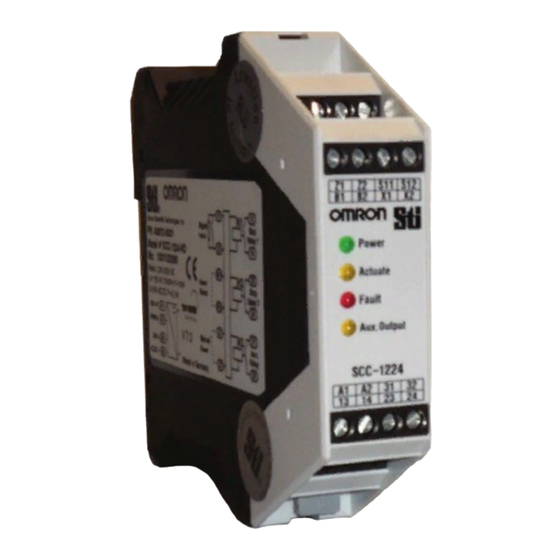
SGE/SCC Ordering Information Edge Controller Safety Appearance Auxiliary output Ratings Terminal Model output SPST-NO (One-shot timer that turns ON between SCC-1224 two and three seconds after the application of pressure to the safety edge) DPST-NO 24 VDC Screw terminals SPST-NO (Kept ON during the application of SCC-1224ND pressure to the safety edge) -
Page 9: Specifications
SGE/SCC Specifications Edge Controller Model SCC-1224 Item SCC-1224ND Safety edge inputs Up to five series connections on the safety edges Response time 13 ms max. Power supply voltage 115 VAC±5%, 3.3 VA or 24 VDC±10%, 1.5 VA Safety output DPST-NO (Rated resistive load: 250 VAC/30 VDC 4A) SPST-NO SCC-1224: One-shot timer that turns ON between two and three seconds after the application of pressure to the Auxiliary output... - Page 10 SGE/SCC Mechanical Force Chemical Resistance Material EPDM Material EPDM SGE-225, SGE-245, SGE-225, SGE-245, Model SGE-125 Model SGE-125 SGE-365 SGE-365 Features Strength * 1 Effects * 1 Features Tear Strength Water Resistance (Resistance) Diluted Acids Ultimate Tensile Diluted Bases Strength Non-Oxidizing Rebound Acids Elasticity at 20°C...
- Page 11 SGE/SCC Characteristics Force Distance SGE-225: Characteristic Values for Test Speed v = 10 mm/s) Test Temperature +20°C Force Force - Curve Switching - Point Safety output Closed Safety output Open Distance V-250N (mm) V-400N SGE-125 : : Characteristic Values for Test Speed = 10 mm/s SGE-125 : Characteristic Values for Test Speed = 100 mm/s)
-
Page 12: Installation
SGE/SCC Installation Safety edges must only be installed by authorized persons. 6. In order to make fitting the safety edge easier, the mounting base and the safety edge should be sprayed with soapy water. Once the 1. To facilitate installation of the safety edge, the mounting base may soap suds have evaporated, the safety edge is firmly fitted in the only be attached to even surfaces. - Page 13 SGE/SCC Connections Internal Connection Diagram SCC-1224 S11 S12 Z1 Z2 13 23 31 SCC-1224ND AC power supply circuit Main circuit DC power supply circuit X1 X2 14 24 32 Wiring for input/output SCC-1224 SCC-1224ND Z1,Z2 Reset input S11,S12 Manual/auto reset switch input B1,B2 Z2 S11 S12 X1,X2...
- Page 14 SGE/SCC Dimensions/Terminal Arrangement (Unit: mm) Edge Controller SCC-1224 Terminal Arrangement SCC-1224ND Z2 S11 S12 B2 X1 X2 Power Power Actuate Actuate Fault Fault Aux. Output Aux. Output SCC-1224 A2 31 32 14 23 24 22.5 Safety Edge SGE-125 SGE-225 SGE-245 SGE-245L...
- Page 15 SGE/SCC SGE-365 10.5 15.5 17.6 35.2 Mounting Bases For SGE-125 For SGE-225/245 For SGE-225/245 L-shaped For SGE-365 For SGE-365 L-shaped 17.6 Connectors Connector (male) Terminal code: M Connector (female) Terminal code: F Pin arrangement Pin arrangement 33.9 35.4 4(Black) 4(Black) 1(Brown) 3(Blue) 3(Blue)
-
Page 16: Application Examples
SGE/SCC Application Examples PL/safety category Model Stop category Reset Safety Edge/Edge Controller SGE+SCC PLe/3 equivalent Safety Door Switch D4GS-N/D4NS/D4BS Manual/Auto Safety Relay Unit G9SB (A Safety Relay Unit or Safety Controller other than the G9SB can be used.) Note: The above PL is only the evaluation result of the example. The PL must be evaluated in an actual application by the customer after confirming the usage conditions. -
Page 17: Safety Precautions
SGE/SCC Safety Precautions !WARNING Precautions for Safe Use Edge Controller Always verify the operation of the safety functions before (1) Be sure to turn OFF the power before performing wiring. Do not starting the system. Not doing so many result in the safety touch any of the terminals while the power is being supplied. -
Page 18: Safety Category
The product may be damaged and may not Safety Edge function properly. (1) Make sure to use the Safety Edge SGE series in combination with the Edge Controller SCC series or Safety controller G9SP series. (2) Adhesion of solvent... - Page 19 Warranty and Limitations of Liability WARRANTY OMRON’s exclusive warranty is that the products are free from defects in materials and workmanship for a period of one year (or other period if specified) from date of sale by OMRON. OMRON...
- Page 20 The Netherlands CA 94555 U.S.A. Tel: (31)2356-81-300/Fax: (31)2356-81-388 Tel: (1) 510-608-3400/Fax: (1) 510-744-1442 © OMRON Corporation 2009-2017 All Rights Reserved. OMRON (CHINA) CO., LTD. OMRON ASIA PACIFIC PTE. LTD. In the interest of product improvement, Room 2211, Bank of China Tower, No.
Need help?
Do you have a question about the SGE Series and is the answer not in the manual?
Questions and answers