
Related Manuals for Omron SCC-1224


Summary of Contents for Omron SCC-1224
- Page 1 Safety Edge Controllers SCC-1224 & SCC-1224ND Installation and Operating Manual Original Instructions...
-
Page 2: Table Of Contents
SCC-1224 & SCC-1224ND Safety Edge Controllers Table of Contents 1 --Important Safety Message......page 3 2 --Introduction. -
Page 3: Important Safety Message
M P O R T A N T A F E T Y E S S A G E MPORTANT AFETY ESSAGE The Safety Edge and Controller, when used together as a system, is an emergency stop device when applied, installed, operated, and maintained in accordance with the instructions in this manual. - Page 4 I M P O R T A N T S A F E T Y M E S S A G E Definition of Qualified Person A person who, by possession of a recognized degree in an applicable field or a certificate of professional standing, or who by extensive knowledge, training, and experience, has successfully demonstrated the ability to solve or resolve problems relating to the subject matter and work.
- Page 5 The user must follow all procedures in this manual for proper operation of the Safety Edge and Controller. The enforcement of these requirements is beyond Omron STI’s control. The employer has the sole responsibility to follow the preceding requirements and any procedures, conditions and requirements specific to your machinery.
-
Page 6: Introduction
I N T R O D U C T I O N NTRODU The Omron STI Safety Edge and Safety Edge Controller, when connected together, provide the operator controls and switching electronics for an emergency stop system that can cover large areas of a machine, door, gate, etc. -
Page 7: Theory Of Operation
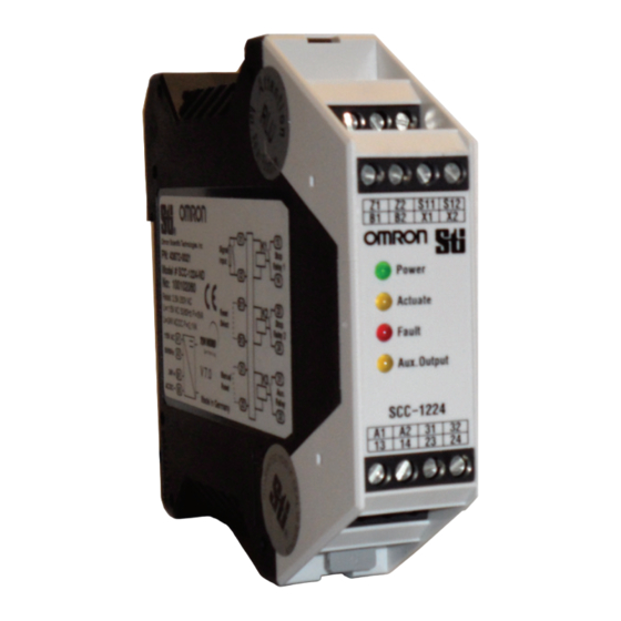
A F E T Y U T P U T S The positive-guided relay outputs of the SCC-1224 and SCC-1224ND are referred to as safety outputs. They are turned off when an object or person activates the Safety Edge. Two Normally Open contacts are provided across terminals 13, 14 and 23, 24. - Page 8 Indicators 4. 4. I NDICATORS There are four LED lamps on the SCC-1224 and SCC-1224ND Safety Edge Controller. Please see Figure 5-2 for the physical location of each indicator. These LEDs are identified on the controller. • Green LED Power Indicates that main power has been applied to the controller.
-
Page 9: Modes Of Operation
A1, A2 Supply Voltage 115 VAC 50/60 Hz 31, 32 Auxiliary Output - SCC-1224: Contacts close when Safety Edge is operated and Delayed To Open after 1 to 3 seconds. - SCC-1224ND: Contacts close when Safety Edge is operated and remain closed until the Safety Edge is returned to normal. - Page 10 (No Connection for Auto Start) Safety Edge Input Supply Voltage 24 VAC/DC Power Actuate Fault Aux. Output SCC-1224 Auxiliary Output (MUST NOT Supply Voltage be used in the Safety Circuit) 115 VAC 50/60 HZ Safety Output 2 Safety Output 1...
- Page 11 A1, A2 Supply Voltage 115 VAC 50/60 Hz 31, 32 Auxiliary Output - SCC-1224: Contacts close when Safety Edge is operated and Delayed To Open after 1 to 3 seconds. - SCC-1224ND: Contacts close when Safety Edge is operated and remain closed until the Safety Edge is returned to normal.
- Page 12 Install this Jumper for Start/Restart Inerlock Mode Supply Voltage 24 VAC/DC Safety Edge Input Power Actuate Fault Aux. Output SCC-1224 AuxiliaryOutput (MUST NOT Supply Voltage be used in the Safety Circuit) 115 VAC 50/60 HZ Safety Output 1 Safety Output 2...
- Page 13 O D E S O F P E R A T I O N Start/ Restart Interlock Mode Power = 24 VDC MPCE 2 MPCE 1 (21) (22) (21) (22) MPCE 1 MPCE 2 (13) (14) (13) (14) MPCE 1 MPCE 2 To Machine (33)
-
Page 14: Specifications
S P E C I F I C A T I O N S Maximum Response Time: <13 ms PECIFICATIONS 6. 1. M : < 1 3 A X I M U M E SP ON S E I M E Indicators: —... - Page 15 P E C I F I C A T I O N S Mechanical Switching Times Aux Outputs: * These contact must never to be used in the safety circuit. — Response time 0.5 s — Release time 3 s 6.
-
Page 16: Installation
Mounting NSTALLATION 7 . 1 . M OUNTING The SCC-1224 controller is a DIN rail mounted controller. 7 . 2 . C O N N E C T I N G T H E A F E T Y D G E S 7.2.1... - Page 17 N S T A L L A T I O N Setup 7.2.2 ONNECTING EVERAL AFETY WARNING! Safety Edges Input MUST NOT be switched in parallel. The Safety Edge input X1, X2 can be used to connect one or several Safety Edges.
- Page 18 I N S T A L L A T I O N Setup 7.3.3 OUTING If the wire is to be fed through the aluminum rail, drill a 5/16 hole in the mounting rail. Be sure that the hole is properly de-burred to prevent damage to the wire.
- Page 19 N S T A L L A T I O N Setup 7.3.5 ARNING NCORRECT OUNTING ETHOD Do not attempt to push or pull the Safety Edge into the aluminum rail. This can cause damage to the safety contact. Figure 7-6 Incorrect Mounting Method 7.3.6 NSERTING THE PROFILE INTO LUMINUM...
-
Page 20: Warranty & Additional Information
Omron STI’s liability hereunder, in any case, is expressly limited to repair or replacement (at Omron Sti’s option) of goods. - Page 21 Service Department. 8. 3. R ETURNS Whenever you return a product to Omron STI (even if the product is in warranty) please Contact our Customer Service Department and request a Returned Goods Authorization number (RGA). Safety Edge Controllers Manual 99640-0010 Rev.P...
- Page 22 - D E C L A R A T I O N O F C O N F O R M I T Y I N F O R M A T I O N A - D PPENDIX ECLARATION OF ONFORMITY NFORMATION Safety Edge Controllers Manual 99640-0010 Rev.P...
- Page 23 Buyer indemnifies Omron against all related costs or expenses. rights of another party. 10. Force Majeure. Omron shall not be liable for any delay or failure in delivery 16. Property; Confidentiality. Any intellectual property in the Products is the exclu-...
- Page 24 OMRON ELETRÔNICA DO BRASIL LTDA • HEAD OFFICE São Paulo, SP, Brasil • 55.11.2101.6300 • www.omron.com.br OMRON EUROPE B.V. • Wegalaan 67-69, NL-2132 JD, Hoofddorp, The Netherlands. • +31 (0) 23 568 13 00 • www.industrial.omron.eu Authorized Distributor: Automation Control Systems •...
Need help?
Do you have a question about the SCC-1224 and is the answer not in the manual?
Questions and answers