Table of Contents
Advertisement
Quick Links
Advertisement
Table of Contents

Related Manuals for Flowserve HDX Series


Summary of Contents for Flowserve HDX Series
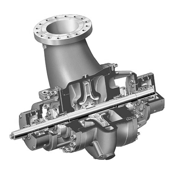
- Page 1 USER INSTRUCTIONS HDX centrifugal pumps Installation Operation Single stage, double suction, radially split volute type Maintenance centrifugal pumps PCN=85392696 – 01/11 (E) Original instructions These instructions must be read prior to installing, operating, using and maintaining this equipment.
-
Page 2: Table Of Contents
HDX USER INSTRUCTIONS ENGLISH 85392696 - 01/11 CONTENTS PAGE PAGE CONTENTS ............... 2 6 MAINTENANCE ............33 6.1 General ............33 1 INTRODUCTION AND SAFETY ......4 6.2 Maintenance schedule........34 1.1 General ............4 6.3 Spare parts .............35 1.2 CE marking and approvals....... 4 6.4 Recommended spares (according to API) ..35 1.3 Disclaimer ............ - Page 3 HDX USER INSTRUCTIONS ENGLISH 85392696 - 01/11 INDEX PAGE Nameplate and safety labels (1.7) ....... 8 Additional sources of information (10.3) ..... 59 Noise level (1.9) ........... 9 Alignment methods (4.5.2) ......... 18 Ordering of spares (6.3.1) ........35 Assembly (6.9)............ 41 Other relevant documentation and manuals(10) 59 Associated equipment (2.4.1.5)......
-
Page 4: Introduction And Safety
Flowserve committed continuous quality insufficient and is not guaranteed by Flowserve as improvement and being at service for any further to its completeness or accuracy. information about the product in its installation and operation or about its support products, repair and... -
Page 5: Safety
Do not use pump as a support for piping. Do not instructions where non-compliance will involve a high mount expansion joints, unless allowed by Flowserve risk to personal safety or the loss of life. in writing, so that their force, due to internal pressure, acts on the pump flange. - Page 6 Where Flowserve has supplied only the bare shaft GUARDS MUST NOT BE REMOVED WHILE pump, the Ex rating applies only to the pump. The...
- Page 7 ATEX Ex rating on the nameplate. These are based device. on a maximum ambient of 40 °C (104 °F); refer to Flowserve for higher ambient temperatures. Avoid mechanical, hydraulic or electrical overload by using motor overload trips, temperature monitor or a...
-
Page 8: Nameplate And Safety Labels
HDX USER INSTRUCTIONS ENGLISH 85392696 - 01/11 systems and any heating and cooling systems are adversely affect the ambient conditions. Where there properly filled. is a risk from such tools or materials; maintenance must be conducted in a safe area. If the operation of the system cannot avoid this It is recommended that a maintenance plan and condition the fitting of an appropriate dry run... -
Page 9: Noise Level
HDX USER INSTRUCTIONS ENGLISH 85392696 - 01/11 1.9 Noise level The dBA values are based on the noisiest ungeared electric motors that are likely to be encountered. When pump noise level exceeds 85 dBA attention They are Sound Pressure levels at 1 m (3.3 ft) from must be given to prevailing Health and Safety the directly driven pump, for "free field over a Legislation, to limit the exposure of plant operating... -
Page 10: Transport And Storage
Any shortage and or damage must be reported Make sure that any equipment used to immediately to Flowserve and received in writing lift the pump or any of its components is capable of within one month of receipt of the equipment. Later supporting the weights encountered. -
Page 11: Storage
HDX USER INSTRUCTIONS ENGLISH 85392696 - 01/11 Inspect all covers over pump openings and piping connections. If covers or seals for the covers are damaged or loose, they are to be removed, and a visual inspection made of the accessible interior areas for accumulation of foreign materials or water. -
Page 12: Recycling And End Of Product Life
This inspection may include, FLOWSERVE standard or 'special' as required by the not necessarily in its entirety and not limited to the contract specification. Refer to FLOWSERVE for the following: description of paints and preservatives used on this order if needed. -
Page 13: Pump Description
HDX USER INSTRUCTIONS ENGLISH 85392696 - 01/11 3 PUMP DESCRIPTION 3.3.2 Impeller The standard double suction closed type impeller is 3.1 Configurations mounted with an interference fit and keyed to the shaft, positively secured against axial movements by The HDX pumps are single stage, double suction a step in the shaft and a threaded shaft nut. -
Page 14: Performance And Operating Limits
In case of doubt, contact There are two kinds of NPSH: the NPSH i s the head the nearest FLOWSERVE office. required by the pump to cover the losses in the pump suction - that is shown on the pump characteristic 3.4.1 Effect of specific gravity... -
Page 15: Installation
4.1 Location requirements particularly if flow has changed. If in The pump should always be located as near as doubt please consult your nearest Flowserve office possible to the suction supply. for advice and details of the minimum allowable Install the unit close to the source of the liquid to be margin for your application. - Page 16 HDX USER INSTRUCTIONS ENGLISH 85392696 - 01/11 In case of installation over a steel structure (platform) ensure that the top of the steel structure is cleaned and degreased. In order to obtain the parallelism and flatness of pads required by API standard, baseplate has to be properly levelled by levelling screws provided on it and clamping the baseplate at the foundation bolts only (For proper detailed procedure...
-
Page 17: Grouting
HDX USER INSTRUCTIONS ENGLISH 85392696 - 01/11 4.3.2 Method of levelling baseplate using wedges 4.4.1 Fully Grouted Baseplates or shims a) Level the baseplate by using a machinist's level on the machined surfaces of the pump and driver pads. Levelling is best achieved by adjusting the FINISHED GROUT shim pack thickness under each holding bolt. -
Page 18: Initial Alignment
HDX USER INSTRUCTIONS ENGLISH 85392696 - 01/11 4.5.2.1 Shaft/Coupling alignment Shaft alignment must be correct for successful operation. Rapid wear, noise, vibration and actual damage to the equipment may be caused by shaft misalignment. The shafts must be aligned within the limits given within this section. - Page 19 HDX USER INSTRUCTIONS ENGLISH 85392696 - 01/11 4.5.2.3 Alignment using a graph (Reverse Alignment) Ensure pump and driver are isolated electrically and the half couplings are disconnected. The alignment MUST be checked. Although the pump will have been aligned at the factory it is most likely that this alignment will have been disturbed during transportation or handling.
-
Page 20: Piping
In case of doubt down bolts to required values. contact FLOWSERVE. 4.5.4 Hot alignment – Pump and driver dowels Suction and discharge piping should be of ample... - Page 21 Refer local angle of divergence of 15 degrees. FLOWSERVE branch to determine if a bypass is d) Use only eccentric reducers with the straight side required. Mechanical damage may result from on the top. continuous operation at flows less than specified.
-
Page 22: Final Shaft Alignment Check
If in any doubt contact already fitted. Symbols which FLOWSERVE work on Flowserve for advice. seal connections are as follows: The motor must be wired up in... -
Page 23: Commissioning, Start-Up, Operation And Shutdown
If rotation is not correct recirculating line should be installed according refer to motor manual for appropriate connections FLOWSERVE recommendations. to change rotation (Shut down all power prior to change). Where possible avoid severe thermal shocks due to... - Page 24 HDX USER INSTRUCTIONS ENGLISH 85392696 - 01/11 the cross arms which support the glass reservoir, as illustrated for TRICO oiler in section 5.1.2. Figure 5.1 The oil circulation is ensured by slinger according to the description as follow. Line bearing & thrust bearings side lubrication: •...
- Page 25 HDX USER INSTRUCTIONS ENGLISH 85392696 - 01/11 Figure 5.5 5.1.2 TRICO oiler setting (standard) TRICO is used only on ball ball lubrication and sleeve ball lubrication: Figure 5.4 a) Initial fill via top of housing, using overflow plug to establish correct level. 5.1.1.3 KTB Lubrication The oil circulation is ensured by an high pressure b) Release thumb screw and remove bottle.
- Page 26 HDX USER INSTRUCTIONS ENGLISH 85392696 - 01/11 required to fill the bearing housing up to the cross arm level and no air bubbles appear in the bottle. d) Remove bottle and ascertain that the oil level is 6 mm (0.24 in.) from the centre line of oiler connection.
- Page 27 HDX USER INSTRUCTIONS ENGLISH 85392696 - 01/11 ½”to¼” NPT adapter oil mist inlet connection ¼” NPT vent connection ½” NPT drain connection Thrust bearing ¼” NPT inlet connection ¼” NPT vent connection ½” NPT drain connection Figure 5.8 Remove inlet and outlet pipe plugs from above connections.
-
Page 28: Pump Lubricants
HDX USER INSTRUCTIONS ENGLISH 85392696 - 01/11 5.2 Pump Lubricants 5.2.1 Recommended oil lubricants Oil Ring or Slinger Lubrication Pure Oil Mist Lubrication Lubrication service Ball Bearing Mineral Oil Mineral Oil Type (Petroleum Based) (Petroleum Based) Viscosity mm ²/s 40 ºC [cSt] -5 to 75 up to 85 -30 and above... - Page 29 HDX USER INSTRUCTIONS ENGLISH 85392696 - 01/11 If a synthetic lubricant (fire resistant fluid) is to be used instead of the normal type oil for the lubrication Bearing Designation Oil Fill Capacity Bearing of bearings, gears etc., the material of all gaskets and Housing D.E.
-
Page 30: Direction Of Rotation
HDX USER INSTRUCTIONS ENGLISH 85392696 - 01/11 5.2.3 Bearing housing oil limitations Recommended Oil Temperature At Start Up 15.6 °C Bearing Designation Oil Fill Capacity Bearing 60 °F Radial Housing D.E. Side N.D.E. Side Desirable Operating Temperature 60-71 °C Thrust Bearing Bearing Size (*) litres (oz) -
Page 31: Guarding
Preheat pump slowly at a rate not to exceed pump damage. Refer to local FLOWSERVE 55 °C per hour (100 °F per hour). branch to determine if a bypass is required. e) Prime pump and ensure suction valve is open. - Page 32 HDX USER INSTRUCTIONS ENGLISH 85392696 - 01/11 If bearing temperatures are to be monitored it is a) Check suction and discharge pressure gauges. essential that a benchmark temperature is recorded b) Check pressure gauges on each side of suction at the commissioning stage and after the bearing strainer.
-
Page 33: Normal Start Up
Before attempting to disassemble pump, pump implications of any change. If in doubt contact your must be isolated from system, by closing suction and nearest Flowserve office. discharge system valves, drained of liquid and cooled, if pump is handling hot liquid. -
Page 34: Maintenance Schedule
Contact Flowserve if the problem persists. 6.2.4 Inspection (after 3 years) a) Check internal condition of pump and all ancillary 6.2.1 Routine inspection (daily/weekly) pipework for corrosion/erosion. -
Page 35: Spare Parts
2 - sets of gaskets and o-ring 2 - wear rings set (2 rotating + 2 stationary) 6.3.1 Ordering of spares 1 - mechanical seals Flowserve keep records of all pumps that have been 1 - labyrinth and deflector set supplied. When ordering spares the following... -
Page 36: Fastener Torques
Before dismantling the pump for of the casing and then opening the drains overhaul, ensure genuine Flowserve replacement situated at the bottom of the casing. parts are available. g) Drain the bearing housings of oil by removing the... - Page 37 HDX USER INSTRUCTIONS ENGLISH 85392696 - 01/11 It is advisable to thoroughly drain and dry off the h) Release locking tab of thrust bearing lock- base plate before attempting any maintenance washer. Loosen and remove thrust bearing lock work on the pump. nut and lock-washer.
-
Page 38: Examination Of Parts
HDX USER INSTRUCTIONS ENGLISH 85392696 - 01/11 e) Carefully lift pump shaft just enough so that lower Unscrew the impeller locking nut using a pin half sleeve bearing can be removed. spanner wrench. Remove the nut. Unbolt and remove lower half of line bearing g) Clean shaft and remove impeller as follows: housing. - Page 39 HDX USER INSTRUCTIONS ENGLISH 85392696 - 01/11 PUMP TYPE HDX M INIMUM DIAMETER CLEARANCES Minimum Diameter Clearance Minimum Diameter Clearance Temp. up to 260°C Temp. above 260°C (500°F) (500°F) Wear ring. Wear ring Wear ring Nominal diameter CastIron /Bronze 316 Stn. Steel CastIron/Bronze 316 Stn.
- Page 40 HDX USER INSTRUCTIONS ENGLISH 85392696 - 01/11 circumstances. Split the outer ring with a small Unless extreme care is used when removing an anti- hand grinder, saw through the ball/roller retainer, friction bearing, the bearing may be damaged to the and split the inner ring about three quarters extent that is no longer useable.
-
Page 41: Assembly
HDX USER INSTRUCTIONS ENGLISH 85392696 - 01/11 d) Bearing seals are not totally leak free devices. Oil from these may cause staining adjacent to the bearings. 6.9 Assembly To assemble the pump consult the sectional drawings, see section 8, Parts list and drawings. Ensure threads, gasket and O-ring mating faces are clean. - Page 42 HDX USER INSTRUCTIONS ENGLISH 85392696 - 01/11 d) Thrust and line bearings can now be fitted. Check the duplex bearings are mounted back-to-back. e) Fit slinger, lock-washers and lock nuts. Tighten lock nuts and lock tab on lock-washers. Install bearing housings sliding them over thrust and line bearings.
- Page 43 HDX USER INSTRUCTIONS ENGLISH 85392696 - 01/11 Lift and install lower halves of thrust and line Check that rotor is axially centralized, and bearing housings against their respective seats establish total thrust end play, (about 0.28 mm) on casing brackets. Tighten all bolting. by using shim or machining at inner face of thrust Pour a small amount of lubricating oil on lower bearing cover.
-
Page 44: Faults; Causes And Remedies
Speed too high. CONSULT FLOWSERVE. Total head of system higher than differential head of pump. Check system losses. Remedy or CONSULT FLOWSERVE. Total head of system lower than pump design head. Specific gravity of liquid different from design. Check and CONSULT FLOWSERVE. - Page 45 ⇓ ⇓ PROBABLE CAUSES POSSIBLE REMEDIES CONSULT FLOWSERVE. Rotating part rubbing on stationary part internally. Check and CONSULT FLOWSERVE, if necessary. Bearings worn Replace bearings. Wearing ring surfaces worn. Replace worn wear ring/surfaces. Impeller damaged or eroded. Replace or CONSULT FLOWSERVE for improved material selection.
-
Page 46: Parts List And Drawings
HDX USER INSTRUCTIONS ENGLISH 85392696 - 01/11 8 PARTS LIST AND DRAWINGS 8.1 HDX Antifriction Bearing + Slinger Lubrication 8.1.1 Parts list Ref no Description Ref no Description Ref no Description 1100 Casing 3130.2 Bearing Bracket 4510.1 Gasket 1221.1 Casing Cover 3260.1 Bearing Cover 4510.2... - Page 47 HDX USER INSTRUCTIONS ENGLISH 85392696 - 01/11 8.2 HDX Antifriction Bearing + Oil Mist Lubrication 8.2.1 Parts list Ref no Description Ref no Description Ref no Description 1100 Casing 3130.2 Bearing Bracket 4610.4 “O” Ring 1221.1 Casing Cover 3260.1 Bearing Cover 4610.5 “O”...
- Page 48 HDX USER INSTRUCTIONS ENGLISH 85392696 - 01/11 8.3 HDX Antifriction Bearing + Slinger Lubrication + Fan Cooling 8.3.1 Parts list Ref no Description Ref no Description Ref no Description 1100 Casing 3130.2 Bearing Bracket 4610.1 “O” Ring 1221.1 Casing Cover 3260.1 Bearing Cover 4610.2...
- Page 49 HDX USER INSTRUCTIONS ENGLISH 85392696 - 01/11 8.4 HDX Antifriction Bearing + Oil Mist Lubrication + Fan Cooling 8.4.1 Parts list Ref no Description Ref no Description Ref no Description 1100 Casing 3130.1 Bearing Bracket 4610.3 “O” Ring 1221.1 Casing Cover 3130.2 Bearing Bracket 4610.4...
- Page 50 HDX USER INSTRUCTIONS ENGLISH 85392696 - 01/11 8.5 HDX Antifriction Bearing + Slinger Lubrication + Water Cooling 8.5.1 Parts list Ref no Description Ref no Description Ref no Description 1100 Casing 3260.1 Bearing Cover 4510.3 Gasket 1221.1 Casing Cover 3260.2 Bearing Cover 4610.1 “O”...
- Page 51 HDX USER INSTRUCTIONS ENGLISH 85392696 - 01/11 8.6 HDX Antifriction Bearing + Slinger Lubrication + Inpro Seals 8.6.1 Parts list Ref no Description Ref no Description Ref no Description 1100 Casing 3260.1 Bearing Cover 4300.3 Inpro Seals 1221.1 Casing Cover 3260.2 Bearing Cover 4510.1...
- Page 52 HDX USER INSTRUCTIONS ENGLISH 85392696 - 01/11 8.7 HDX Antifriction Bearing + Oil Mist Lubrication + Inpro Seals 8.7.1 Parts list Ref no Description Ref no Description Ref no Description 1100 Casing 3130.2 Bearing Bracket 4610.1 “O” Ring 1221.1 Casing Cover 3260.1 Bearing Cover 4610.2...
- Page 53 HDX USER INSTRUCTIONS ENGLISH 85392696 - 01/11 8.8 HDX Antifriction Bearing + Slinger Lubrication + Inpro Seals + Fan Cooling 8.8.1 Parts list Ref no Description Ref no Description Ref no Description 1100 Casing 3260.2 Bearing Cover 4610.1 “O” Ring 1221.1 Casing Cover 3260.3...
- Page 54 HDX USER INSTRUCTIONS ENGLISH 85392696 - 01/11 8.9 HDX Antifriction Bearing + Slinger Lubrication + Inpro Seals + Water Cooling 8.9.1 Parts list Ref no Description Ref no Description Ref no Description 1100 Casing 3260.3 Bearing Cover 4610.1 “O” Ring 1221.1 Casing Cover 3712.1...
- Page 55 HDX USER INSTRUCTIONS ENGLISH 85392696 - 01/11 8.10 HDX Antifriction Bearing + Coke Crusher 8.10.1 Parts list Ref no Description Ref no Description Ref no Description 1100 Casing 3712.1 Bearing Nut 4610.2 “O” Ring 1221.1 Casing Cover 3712.2 Bearing Nut 4610.3 “O”...
- Page 56 HDX USER INSTRUCTIONS ENGLISH 85392696 - 01/11 8.11 HDX Sleeve Ball Bearing + Oil Ring Lubrication 8.11.1 Parts list Ref no Description Ref no Description Ref no Description 3013 Thrust Bearing 4200 Mechanical Seal 3240 Intermediate Bearing Sleeve 3400 Bearing Sleeve 3854 Oil Filler Plug 4132...
- Page 57 HDX USER INSTRUCTIONS ENGLISH 85392696 - 01/11 8.12 HDX Sleeve KTB Bearing + Forced Feed Lubrication 8.12.1 Parts list Ref no Description Ref no Description Ref no Description 3630 Thrust Bearing Pad 4200 Mechanical Seal 6700.1 3500 Bearing Shell 3854 Oil Filter Plug 6700.2 3126.1...
- Page 58 HDX USER INSTRUCTIONS ENGLISH 85392696 - 01/11 8.13 HDX Antifriction Bearing + Purge Oil Mist 8.13.1 Parts list Ref no Description Ref no Description Ref no Description 3013 Thrust Bearing 3854.1 Oil Filler Plug 3862.2 Lubricating Disk Thrower 3010 Radial Bearing 3854.2 Oil Filler Plug 4132...
-
Page 59: Certification
8.14 General arrangement drawing 10.2 Change notes The typical general arrangement drawing and any If any changes, agreed with Flowserve, are made specific drawings required by the contract will be to the product after its supply, a record of the... - Page 60 Telephone 1 713 803 4434 Fax 1 713 803 4497 Asia Pacific Flowserve Pte. Ltd 10 Tuas Loop Singapore 637345 Telephone +65 6771 0600 Fax +65 6779 4607 To find your local Flowserve representative please use the Sales Support Locator System found at www.flowserve.com...
Need help?
Do you have a question about the HDX Series and is the answer not in the manual?
Questions and answers