Table of Contents
Advertisement
Quick Links
Advertisement
Table of Contents

Subscribe to Our Youtube Channel
Related Manuals for Bender ISOMETER isoGEN523-S4-4


Summary of Contents for Bender ISOMETER isoGEN523-S4-4
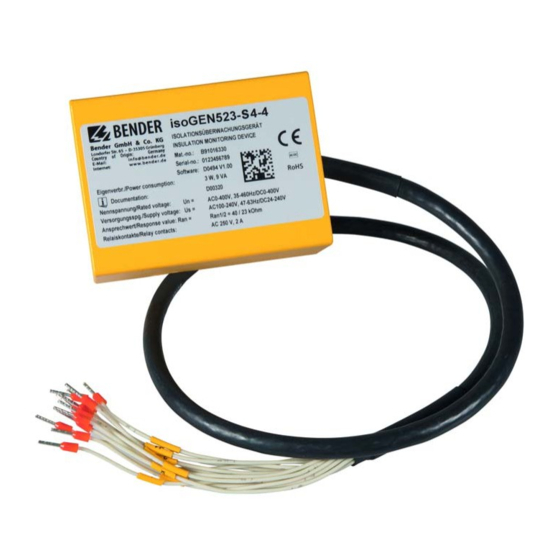
- Page 1 Manual ISOMETER® isoGEN523-S4-4 Insulation monitoring device for unearthed AC, AC/DC and DC systems (IT systems) up to 3(N)AC, AC 400 V, DC 400 V Suitable for use in applications using generators according to DIN VDE 0100-551 Software version: D0494 V1.xx isoGEN523_D00320_04_M_XXEN/06.2018...
- Page 2 Bender GmbH & Co. KG P.O. Box 1161 • 35301 Gruenberg • Germany Londorfer Str. 65 • 35305 Gruenberg • Germany Tel.: +49 6401 807-0 • Fax: +49 6401 807-259 E-mail: info@bender.de • www.bender.de © Bender GmbH & Co. KG All rights reserved.
-
Page 3: Table Of Contents
Table of contents 1. Important information ................6 How to use this manual ................... 6 Technical support: service and support ............ 7 1.2.1 First level support ....................7 1.2.2 Repair service ...................... 7 1.2.3 Field service ......................8 Training courses ....................8 Delivery conditions ................... - Page 4 Table of contents 3.2.10 Measuring and response times ..............15 3.2.11 Factory settings FAC ..................16 3.2.12 External, combined test or reset button T/R ......... 16 3.2.13 Fault memory ....................16 3.2.14 Interface/protocols ..................17 4. Installation and connection ..............19 Installation ......................
- Page 5 Table of contents 8. Modbus register assignment of the ISOMETER® ......31 Device-specific data type of the ISOMETER® ......... 34 8.1.1 Device name ...................... 34 8.1.2 Measured values ....................34 8.1.2.1 Float = Floating point value of the channels ........35 8.1.2.2 AT&T = Alarm type and test type (internal/external) ......
-
Page 6: Important Information
1. Important information 1.1 How to use this manual This manual is intended for qualified personnel working in electrical engineering and electronics! Always keep this manual within easy reach for future reference. To make it easier for you to understand and revisit certain sections in this manual, we have used symbols to identify important instructions and information. -
Page 7: Technical Support: Service And Support
Delivery of replacement devices in the event of faulty or incorrectly delivered Bender devices Extended guarantee for Bender devices, which includes an in-house repair service or replacement devices at no extra cost Telephone: +49 6401 807-780** (technical issues) -
Page 8: Field Service
ZVEI (Zentralverband Elektrotechnik- und Elektronikindustrie e. V.) (German Electri- cal and Electronic Manufacturer's Association) also applies. Sale and delivery conditions can be obtained from Bender in printed or electronic for- mat. 1.5 Inspection, transport and storage Inspect the dispatch and equipment packaging for damage, and compare the contents of the package with the delivery documents. -
Page 9: Warranty And Liability
13 August 2005 must be taken back by the manufacturer and disposed of properly. For more information on the disposal of Bender devices, refer to our homepage at www.bender-de.com -> Service & support. -
Page 10: Safety Instructions
2.1 General safety instructions Part of the device documentation in addition to this manual is the enclosed "Safety in- structions for Bender products". 2.2 Work activities on electrical installations Only qualified personnel are permitted to carry out the work necessary to install, commission and run a device or system. -
Page 11: Intended Use
Safety instructions 2.3 Intended use Only qualified personnel are permitted to carry out the work nec- essary to install, commission and run a device or system. The ISOMETER® monitors the insulation resistance R of unearthed AC, AC/DC and DC systems (IT systems) with nominal system voltages of 3(N)AC, AC/DC 0…400 V or DC 0…400 V. -
Page 12: Device Description
Fault memory can be activated RS-485 (galvanically isolated) including the following protocols: – BMS interface (Bender measuring device interface) for data exchange with other Bender components – Modbus RTU – IsoData (for continuous data output) 3.2 Functional description The ISOMETER®... -
Page 13: General Measuring Functions
Device description 3.2.3 General measuring functions The ISOMETER® measures the RMS value of the nominal system voltage U between L1/ + and L2/- as well as the residual voltages U (between L1/+ and earth) and U (between L2/- and earth). When coupled to a DC system , the ISOMETER®... -
Page 14: Monitoring The Insulation Resistance
Device description 3.2.5 Monitoring the insulation resistance The two parameters "R1" and "R2" monitor the insulation resistance. The value R1 can only be set higher than the value R2. If the insulation resistance R reaches or falls below the activated values R1 or R2, then this leads to an alarm message. If R exceeds the val- ues R1 or R2 plus the hysteresis value (see table on page... -
Page 15: Malfunction
In addition to the described self test, several functions in the insulation monitoring de- vice are continuously checked during operation. If the error occurs again after restart- ing the device or after restoring the factory settings, please contact Bender Service. 3.2.9 Signalling assignment of the alarm relays K1/K2 The signalling assignment of the alarm relays "K1"... -
Page 16: Factory Settings Fac
Device description Delay on release The delay on release t can be set uniformly for all messages using the parameter "toff", whereby each alarm message specified in the alarm assignment hast its own timer for t . An alarm will continuously be signalled until the threshold value of the re- spective measured value is not violated (including hysteresis) for the period of t with- out interruption. -
Page 17: Interface/Protocols
The ISOMETER® uses the serial hardware interface RS-485 with the following protocols: • BMS The BMS protocol is an essential component of the Bender measuring device interface (BMS bus protocol). Data transmission generally makes use of ASCII characters. The isoGEN523 identifies itself on the BMS bus with the device name "isoGEN423". - Page 18 Device description Parameter address, baud rate and parity can be parameterised via the RS-485 interface. The IsoData protocol is activated by setting "Adr = 0". The parameter value "---" for the baud rate indicates the activated BMS protocol. In this case, the baud rate for the BMS protocol is set to 9,600 baud.
-
Page 19: Installation And Connection
4. Installation and connection Only qualified personnel are permitted to carry out the work necessary to install, commission and run a device or system. Risk of fatal injury due to electric shock! Touching live parts of the system carries the risk of: An electric shock ... -
Page 20: Installation
Installation and connection 4.1 Installation Screw mounting: Fix the device with two M4 screws, see the following sketch. Side view Signal cable (Wires 1-12) Front view 23.5 12.5 Unten Bottom view All dimensions are in mm Abb. 4.1: Dimension diagram (front and side view, bottom view) 4.2 Connection of the device The wires 1 and 2 ("A1"... - Page 21 Installation and connection L1/+ L2/- 12 (E) 5 (KE) 1 (A1) 2 (A2) Test / Reset isoGEN523-S4-4 Interface A Interface Contact 11 Contact 14 Contact 24 Signal cable (Wires 1-12) 4 (L2/-) 3 (L1/+ ) COM465IP 7 (A) 8 (B) 10 (14) 11 (24) 9 (11) 6 (T/R) RS-485...
-
Page 22: Commissioning
Installation and connection Legend for isoGEN523 wiring diagram: Wire number Terminal Connections Connection to the supply voltage U via fuse (line protec- tion): If being supplied from an IT system, both lines have to be protected by a fuse. Connection to the system to be monitored Connection to the system to be monitored Connect to PE. -
Page 23: Parameter Overview
5. Parameter overview 5.1 Response value setting The two parameters that monitor the insulation resistance are "R1" and "R2". The value R1 can only be set higher than the value R2. If the insulation resistance R reaches or falls below the activated values R1 or R2, this leads to an alarm message. If R exceeds the values R1 or R2 plus the hysteresis value (see table below), the alarm will be cleared. -
Page 24: Relay Signalling Assignment "R1" And "R2
Parameter overview 5.2.1 Relay signalling assignment "r1" and "r2" In the alarm assignment, each alarm is assigned to the corresponding relay with the set- ting "on". If the device can assign an asymmetrical insulation fault to the corresponding conductor (L1/+ or L2/-), it will only signal the respective alarm. K1 "r1"... -
Page 25: Interface Configuration
Parameter overview 5.3 Interface configuration Available Setting value Description Value range FAC BMS Modbus Adr = 0 deactivates BMS as well as Mod- bus and activates isoData with continu- 0 / 3 … 90 ) BusAdr. ous data output (115k2, 8E1) “---“... -
Page 26: Function Configuration
Test of the system connection during device test Device test during device S.Ct start Restore factory settings For Bender Service only FAC = Factory settings; Cs = Customer settings 5.6 Measured value description Description Insulation resistance 1 kΩ ... 2 MΩ... -
Page 27: Data Access Using The Bms Protocol
6. Data access using the BMS protocol The BMS protocol is an essential component of the Bender measuring device inter- face (BMS bus protocol). Data transmission generally makes use of ASCII characters. BMS channel no. Operation value Alarm Pre-alarm R1... -
Page 28: Data Access Using The Modbus Rtu Protocol
7. Data access using the Modbus RTU protocol Requests to the ISOMETER® can be made using the function code 0x03 (read multi- ple registers) or the command 0x10 (write multiple registers). The ISOMETER® gen- erates a function-related answer and sends it back. 7.1 Reading out the Modbus register from the ISOMETER®... -
Page 29: Command Of The Master To The Isometer
Data access using the Modbus RTU protocol 7.2.1 Command of the master to the ISOMETER® In this example, the master addresses the ISOMETER® with address 3 and requests that the content of the register with address 3003 is set to 2. Byte Name Example... -
Page 30: Structure Of The Exception Code
Data access using the Modbus RTU protocol 7.3.1 Structure of the exception code Byte Name Example Byte 0 ISOMETER® Modbus address 0x03 Byte 1 Function code (0x03) + 0x80 0x83 Byte 2 Data (exception code) 0x04 Byte 3, 4 CRC16 Checksum 0xE133 isoGEN523_D00320_04_M_XXEN/06.2018... -
Page 31: Modbus Register Assignment Of The Isometer
8. Modbus register assignment of the ISOMETER® Depending on the device condition, the information in the registers is the meas- ured value without alarm; the measured value with alarm 1; the measured value with alarm 2; or only the device error. Measured value Register Device error... - Page 32 Modbus register assignment of the ISOMETER® Regpage Property Description Format Unit Value range 31ister 3000 Reserved 3001 Reserved 3002 Reserved 3003 Reserved 3004 Reserved Pre-alarm value resist- 3005 ance measurement UINT 16 kΩ R2 … 250 "R1" 3006 Reserved Alarm value resist- 3007 ance measurement UINT 16...
- Page 33 Modbus register assignment of the ISOMETER® Regpage Property Description Format Unit Value range 31ister 0 = 8N1 3017 Parity "Adr 2" UINT 16 1 = 8O1 2 = 8E1 Start-up delay "t" dur- 3018 UINT 16 0 …10 ing device start Response delay "ton"...
-
Page 34: Device-Specific Data Type Of The Isometer
Modbus register assignment of the ISOMETER® Regpage Property Description Format Unit Value range 31ister UNIT 16 (ASCII) - 9800 Device name refer to to 9809 Chapter 8 .1.1 Software Software D 9820 UINT 16 ID number number Software version Software 9821 UINT 16 number... -
Page 35: Float = Floating Point Value Of The Channels
Modbus register assignment of the ISOMETER® 8.1.2.1 Float = Floating point value of the channels 0x00 0x01 HiByte LoByte HiByte LoByte S E E E E E E E E M M M M M M M M M M M M M M M M M M M M M M M Representation of the bit order for processing analogue measured values according to IEEE 754 S = Sign;... -
Page 36: R&U = Range And Unit
Modbus register assignment of the ISOMETER® The alarm type is coded by the bits 0 to 2. Bits 3, 4 and 5 are reserved and always have the value 0. Bit 6 or 7 is usually set when an internal or external test has been completed. Other values are reserved. -
Page 37: Alarm Assignment Of The Relays
Modbus register assignment of the ISOMETER® 8.1.3 Alarm assignment of the relays Several alarms can be assigned to each relay. For the assignment of each relay, a 16-bit register is used with the bits described below. The following table applies to relay 1 and relay 2, in which "x"... -
Page 38: Channel Description
Modbus register assignment of the ISOMETER® 8.2 Channel description Measured value description/alarm Comments Value message operating message Insulation fault 1 (0x01) 71 (0x47) Insulation resistance R in Ω Insulation fault 76 (0x4C) Voltage Measured value in V Undervoltage 77 (0x4D) 78 (0x4E) Overvoltage 82 (0x52) - Page 39 Modbus register assignment of the ISOMETER® To convert parameter data, data type descriptions are required. Text representation is not necessary in this case. Value Description of parameters 1023 (0x3FF) Parameter/measured value invalid. The menu item of this parameter is not displayed. 1022 (0x3FE) No measured value/no message 1021 (0x3FD)
-
Page 40: Isodata Data String
9. IsoData data string In IsoData mode, the ISOMETER® continuously sends the whole data string with a cycle time of approximately 1 second. Communication with the ISOMETER® in this mode is not possible and no additional sender may be connected via the RS-485 bus cable. IsoData is activated when the menu item is set to Adr = 0. -
Page 41: Technical Data
10. Technical data 10.1 Tabular representation ( )* = Factory settings Insulation coordination acc. to IEC 60664-1/IEC 60664-3 Definitions: Measuring circuit (IC1) ........................3 (L1/+), 4 (L2/-) Supply circuit (IC2) ............................1(A1), 2 (A2) Output circuit (IC3) ........................9 (11), 10 (14), 11 (24) Control circuit (IC4)....................12 (E), 5 (KE), 6 (T/R), 7 (A), 8 (B) Rated voltage ................................... - Page 42 Technical data Monitored IT system Nominal system voltage U ..................3(N)AC, AC 0…400 V/DC 0…400 V Tolerance of U ................................+25 % Frequency range of U ..........................DC, 35…460 Hz Measuring circuit Measuring voltage U ..............................±12 V Measuring current I at R = 0 ..........................
- Page 43 Technical data Cable length (9.6 kbits/s) ............................≤ 1200 m Cable: twisted pair, shield connected to PE on one side ............... min. J-Y(St)Y 2 x 0.6 Terminating resistor ........................120 Ω (0.25 W), external Device address, BMS bus, Modbus RTU ......................3…90 (3)* Switching elements Switching elements....................
-
Page 44: Standards And Certifications
Technical data 10.2 Standards and certifications The ISOMETER® has been developed in compliance with the following standards: DIN EN 61557-8 (VDE 0413-8): 2015-12/Ber1: 2016-12 IEC 61557-8:2014/COR1: 2016 DIN VDE 0100-551: 2017-02 Subject to change! The specified standards take into account the edition valid until 06.2018 unless otherwise indicated. - Page 45 Technical data isoGEN523_D00320_04_M_XXEN/06.2018...
- Page 46 Index Installation 19 - screw fixing 20 Commissioning 22 Intended use 11 Connection 19 Interface/protocols - BMS 17 - IsoData 17 Data access - Modbus RTU 17 - BMS 27 IsoData data string 40 - Modbus RTU 28 Isolation from the system to be monitored 13 dc mode 12 Delivery conditions 8 Device description 12...
- Page 47 INDEX Safety instructions 10 Self test - Automatic 14 Self test/Device fault 14 Service 7 Signalling assignment 15 Standards and certifications 44 Support 7 Technical data 41 Technical support 7 Training courses 8 Warranty and liability 9 Workshops 8 isoGEN523_D00320_04_M_XXEN/06.2018...
- Page 48 Bender GmbH & Co. KG P.O. Box 1161 • 35301 Gruenberg • Germany Londorfer Str. 65 • 35305 Gruenberg • Germany Tel.: +49 6401 807-0 • Fax: +49 6401 807-259 E-mail: info@bender.de • www.bender.de © Bender GmbH & Co. KG All rights reserved.
Need help?
Do you have a question about the ISOMETER isoGEN523-S4-4 and is the answer not in the manual?
Questions and answers