
Related Manuals for Allen-Bradley 1770-SB

Summary of Contents for Allen-Bradley 1770-SB
- Page 1 (217) 352-9330 | Click HERE Find the Rockwell / Allen-Bradley 1773-L1A at our website:...
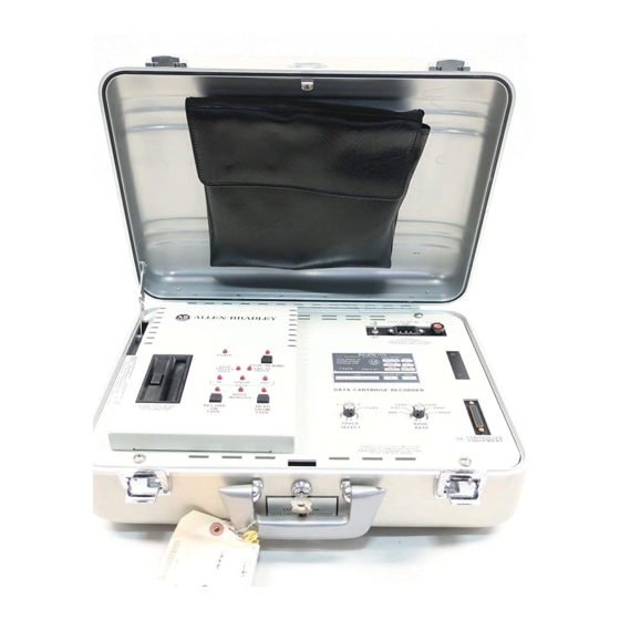
- Page 2 Allen Bradley User Manual Data Cartridge Recorder (Cat. No. 1770 SB) Artisan Technology Group - Quality Instrumentation ... Guaranteed | (888) 88-SOURCE | www.artisantg.com...
-
Page 3: Table Of Contents
Table of Contents Introduction ........Scope of Manual . - Page 4 Table of Contents Recording Series 8200 CNC Part Programs ....4 15 Reading Series 8200 CNC Part Programs ....4 17 Recording Series 8200 CNC PAL Programs .
-
Page 5: Introduction
Recorder (cat. no. 1770-SB). Familiarity with the Allen-Bradley processor to be used with the recorder is assumed. If unfamiliar with an Allen-Bradley processor to be used with the recorder, refer to the document specified in table 1.A for further information. -
Page 6: General Information
Refer to publication 6005-800 for use with the XL3 translator package. Data Cartridge The data cartridge recorder uses the Allen-Bradley Mini Data Cartridge (cat. no. 1770-XJ). The mini data cartridge is shown in figure 1.1. It is a 2-track magnetic tape storage medium. Each track stores 72K words (max) (K-1024). -
Page 7: Marking Tapes
Chapter 1 Introduction The contents of the mini-data cartridge can be protected using the RECORD tab (Figure 1.1). If the tab is positioned to the right, the tape is protected. If the tab is positioned to the left, the tape is unprotected and can be recorded on. -
Page 8: Data Cartridge Repacking
Chapter 1 Introduction Data Cartridge Repacking Before inserting a data cartridge into the recorder, verify that the power ON/OFF switch is in the ON position. This ensures that when the cartridge is inserted, an automatic repacking operation is initiated. The repacking operation involves a fast forward to the EOT (end of tape) marker, and a fast reverse to the BOT (beginning of tape) marker. -
Page 9: Recorder Hardware
Chapter Recorder Hardware General Description This chapter describes the various switches, indicators, connectors, and labels associated with the Allen–Bradley data cartridge recorder. Switches There are six switches on the recorder. Figure 2.1 shows the position of the switches on the recorder front panel. Table 2.A lists switch functions. Figure 2.1 Data Cartridge Recorder Front Panel POWER... -
Page 10: 230 V Fuse Kit
Chapter 2 Recorder Hardware Table 2.A Data Cartridge Recorder Switches Name Function POWER ON/OFF Toggle switch. Turns recorder power on or off. BAUD RATE Rotary switch. Selects 300, 600, 1200, 2400, 4800 or 9600 baud operation. TRACK SELECT Rotary switch. Selects track 1, track 2, or continuous operation. READ FROM TAPE Momentary action pushbutton switch. -
Page 11: Installation
Installation General PLC programmable controllers connect directly to the data cartridge recorder. Other Allen-Bradley products connect to an Industrial Terminal System (cat. no. 1770-T1,-T2,-T3,-T4), or a 1770-T12 programmer which provides the interface with the recorder. This section describes both types of installation. -
Page 12: Connection To Plc Programmable Controllers
Chapter 3 Installation Figure 3.1 Connection to a PLC Programmable Controller PLC Processor Program POWER Panel Interface Module Cassette Recorder Interconnect Cable (Cat. No. 1774 TD) 10376 Connection to PLC 2 Family and PLC-2 Family and PLC-3 programmable controllers and series 7100 PLC 3 Programmable Controller CNCs require an industrial terminal system connected between the and Series 7100 CNCs... -
Page 13: Connection To Plc 4 Microtrol Programmable Controllers
Chapter 3 Installation Connect the power cable between the recorder and a grounded 115V AC outlet. NOTE: If the recorder has been converted for 230V AC operation, use a 230V AC outlet. Connect a Digital Cassette Recorder Cable (cat. no. 1772-TH) between the recorder and the industrial terminal system. -
Page 14: Connection To Series 8200 Cncs
Chapter 3 Installation Connect the 1770-T12 programmer to the PLC-4 Microtrol programmable controller as described in the PLC-4 Microtrol Programmable Controller Product Guide (publication 1773-800). Connect a Digital Cassette Recorder Cable (cat. no. 1772-TH) between the recorder and the unused connector on the 1770-T12 programmer cable. -
Page 15: Converting For 230 V Ac Operation
Chapter 3 Installation Set the control’s baud rate of 9600 baud. The baud rate can be changed by altering the bits of PAL table 161, index 0. Change bits 2,1,0 to a value of 1,1,0. Do not alter the other bits in index 0 as they control the communications between the control and its peripheral devices. - Page 16 Chapter 3 Installation Remove the front panel from the case. Position the switch on the power supply (Figure 3.6) to the position labeled 230. Reconnect the ground wire and front panel. Replace the fuse with a 0.25A slow blow 3AG fuse (included in the 2130V AC fuse kit).
-
Page 17: Operation
(while the processor is still in the program load mode). This chapter describes the steps required to operate the recorder with other Allen-Bradley products. Table 4.A summarizes the baud rate switch settings. -
Page 18: Recording Plc Programs
Chapter 4 Operation After the required data has been entered into the recorder, you can exit the manual mode by pressing the STOP/REWIND pushbutton. You must press the STOP/REWIND pushbutton a second time to rewind. To transmit data from the data cartridge recorder under manual control, press the READ FROM TAPE pushbutton. -
Page 19: Loading Plc Programs
Chapter 4 Operation Figure 4.1 Error Indicator 10860 I Wait for the RECORD ON TAPE indicator to turn on, then off. Press the STOP/REWIND pushbutton. 10. Wait for the tape to completely rewind. 11. Press the READ FROM TAPE pushbutton. 12. - Page 20 Chapter 4 Operation Figure 4.2 Error Indicator Error Error Error (c) Cat. No. 1774 TL2 (b) Cat. No. 1774 TB (a) Cat. No. 1774 TB2 10861 I Wait for the recorder to complete the repacking operation . Verify that the size of the switch-selected data table in the PLC memory is a least as large as the data table in the recorded program.
-
Page 21: Verifying Plc Programs
Chapter 4 Operation Verifying PLC Programs Procedures for recording and loading include steps for verifying programs. Verification is done by the PLC programmable controller. If using a cat. no. 1774-TB, series B revision C or earlier program panel interface module, do not attempt to verify the tape after data table values have had a chance to change. -
Page 22: Loading Plc 2 Family Programs
Chapter 4 Operation 11. Wait for the tape to completely rewind. 12. Press the READ FROM TAPE pushbutton. 13. If errors are indicated on the CRT, repeat the record operation. 14. When finished recording, remove the data cartridge and position the record protect tab to the right. -
Page 23: Verifying Plc 2 Family Programs
Chapter 4 Operation the error. For example, the first error found is displayed after [SEARCH][0][1] is typed, while the fifth error found is displayed after [SEARCH][0][5] is typed. NOTE: If using a 177-T3 industrial terminal system, steps 9-14 can be replaced by pressing [RECORD][SHIFT][A] on the keyboard. - Page 24 Chapter 4 Operation [A] - Causes the area shown on the industrial terminal CRT monitor as the CURRENT ADDRESS to be recorded on tape. If the prompt DUMP SYSTEM is displayed, and no CURRENT ADDRESS is shown, all user accessible memory is recorded. [Y] - Causes the next lower level of memory to be displayed as the CURRENT ADDRESS.
- Page 25 Chapter 4 Operation 11. When finished recording, remove the data cartridge and position the record protect tab to the right. A detailed discussion of the PLC-3 extended address system appears in the PLC-3 Programmable Controller Programming Manual (publication 1775-801). Recording The User Program and Assistance (HELP) Messages Use the following procedures to record the user program (area E4) and assistance (HELP) messages (area E5.15) of PLC-3 memory: Install the recorder as described in chapter 3.
-
Page 26: Loading Plc 3 Programs
Chapter 4 Operation 16. When finished recording, remove the data cartridge and position the record protect tab to the right. Loading PLC 3 Programs Use the following procedure to load a recorded program into PLC-3 memory: Install the recorder as described in chapter 3. Set the BAUD RATE switch to 9600 baud. -
Page 27: Verifying Plc 3 Programs
Chapter 4 Operation Verifying PLC 3 Programs The procedures for recording and loading include steps for verifying the programs. you can also verify programs at other times by using the following procedure: NOTE: The data table is compared only on the first verification, and only if the PLC-3 programmable controller is left in the PROGRAM LOAD mode. -
Page 28: Loading Plc 4 Microtrol Programs
Chapter 4 Operation Loading PLC 4 Microtrol Use the following procedure to load a recorded program into PLC-4 Programs Microtrol memory: Install the recorder as described in chapter 3. Set the BAUD RATE switch to 1200 baud. Select the track containing the desired program. -
Page 29: Verifying Plc 4 Microtrol Programs
Chapter 4 Operation Verifying PLC 4 Microtrol Use the following procedure to verify that a recorded program matches Programs the program in the memory of the PLC-4 Microtrol programmable controller. Install the recorder as described in chapter 3. Set the BAUD RATE switch to 1200 baud. Select the track containing the desired program. -
Page 30: Loading Series 7100 Cnc Program
Chapter 4 Operation 13. Press the READ FROM TAPE pushbutton. 14. If errors are indicated, repeat the record operation. 15. When finished recording, remove the data cartridge and position the record protect tab to the right. NOTE: If using a 1770T3 industrial terminal system, steps 8-13 can be replaced by pressing [RECORD][SHIFT][B] on the keyboard. -
Page 31: Verifying Series 7100 Cnc Programs
Chapter 4 Operation Verifying Series 7100 CNC The procedures for recording and loading include steps for verifying the Programs programs. you can also verify programs at other times by using the following procedure: Install the recorder as described in chapter 3. Set the BAUD RATE switch to 1200 baud. - Page 32 Chapter 4 Operation Be sure that the write protect tab on the data cartridge is positioned to the left, and insert a data cartridge into the recorder. Wait for the recorder to complete the repacking operations. NOTE: If the recorder is turned off while a tape rewind operation is in progress, the data on the tape will be altered.
-
Page 33: Reading Series 8200 Cnc Part Programs
Chapter 4 Operation Enter the following command through the keyboard: CA, TA, name]. “Name” is the name the program is to be stored under on the cassette. Wait for the RECORD ON TAPE indicator to turn on, then off. After a short delay the DATA IN indicator turns on. Wait for tape motion to stop. - Page 34 Chapter 4 Operation Transferring Part Programs to Memory Use the following procedure to load a recorded program into the Series 8200 CNC’s memory: Install the recorder as described in chapter 3. Set the BAUD RATE switch to 9600 baud. Select the track containing the desired program.
- Page 35 Chapter 4 Operation Wait for the recorder to complete the repacking operation NOTE: If the recorder is turned off while a tape rewind operation is in progress, the data on the tape will be altered. Connect a tape punch to the Series 8200 CNC’s peripheral panel’s tape punch port.
-
Page 36: Recording Series 8200 Cnc Pal Programs
Chapter 4 Operation Wait for the READ FROM TAPE indicator to turn on. After a short delay the DATA OUT indicator turns on. Wait for tape motion to stop. Both indicators should be off. Only the first page of Part Program data will be displayed. Press XMIT to see subsequent pages. -
Page 37: Loading Series 8200 Cnc Pal Programs
Chapter 4 Operation Wait for tape motion to stop. Both indicators should be off. Remove the data cartridge and position the record protect tab to the right. Recording a C Version PAL Program Use the following procedure to store a C version PAL program on the data cartridge recorder: Install the recorder as described in chapter 3. -
Page 38: Recording Series 8200 Cnc Executive Programs
Chapter 4 Operation NOTE: If the recorder is turned off while a tape rewind operation is in progress, the data on the tape will be altered. Select the KYBD (keyboard) mode. Enter the following command through the keyboard: AL,RL,CA]. Wait for the READ FROM TAPE indicator to turn on. After a short delay the DATA OUT indicator turns on. -
Page 39: Loading Series 8200 Cnc Executive Programs And Pal Binary Programs
Chapter 4 Operation Wait for tape motion to stop. Both indicators should be off. NOTE: If the recorder stops unexpectedly and either the DATA IN or RECORD ON TAPE indicator is on in addition to the ERROR indicator, turn the recorder off and then on again. Press the READER RESET key. Repeat the recording operation. -
Page 40: Recording Series 8200 Amp Or Diagnostics Utility Programs
Chapter 4 Operation After a successful program load the switch register should display octal 102077. Recording Series 8200 AMP or Diagnostics Utility Programs Install the recorder as described in chapter 3. Set the baud rate switch to 9600 baud. Set the track switch to track 1 or track 2. -
Page 41: Load Diagnostics From Cartridge To 8200 Cnc
Chapter 4 Operation Insert the data cartridge into the recorder. Wait for the recorder to complete the repacking operation. NOTE: If the recorder is turned off while a rewind operation is in progress, the data on the tape will be altered. The following procedures assume that all information to be loaded is contained on a data cartridge. -
Page 42: Erasing Series 8200 Programs
Chapter 4 Operation Set baud switch to 9600 baud. Set the track switch to the track containing diagnostics program. Set the power ON/OFF switch to the ON position. Insert the data cartridge into the recorder. Wait for the recorder to complete the repacking operation. NOTE: If the recorder is turned off while a tape rewind is in progress, the data on the tape will be altered. - Page 43 Chapter 4 Operation Wait for the END OF TRACK indicator to come on. After a short delay the ERROR indicator turns on and a rewind operation is performed. Both indicators turn off when the operation is complete. 4 27 Artisan Technology Group - Quality Instrumentation ... Guaranteed | (888) 88-SOURCE | www.artisantg.com...
-
Page 44: Maintenance
Chapter Maintenance General When the data cartridge recorder needs repair, contact your local Allen-Bradley Customer Support Services Center. Only routine preventive maintenance should be performed by the user. This section describes this preventive maintenance. Head Cleaning After every ten hours of operation, clean the read/record and erase heads (Figure 5.1) with cotton swabs dipped in a magnetic header cleaner... -
Page 45: Unit Cleaning
Chapter 5 Maintenance Unit Cleaning After every 100 hours of operation, clean the entire unit using the following procedure: Remove the power cord from the recorder and the grounded AC outlet. Remove the four screws which attach the front panel to the case. Disconnect the ground wire from the bottom of the front panel. -
Page 46: Specifications
Chapter Specifications Specifications Power Requirements Data Cartridge Cat. No. 1770-XJ 115/230V AC +10%, 50/60Hz ANSI X3.48-1977 Magnetic Tape Data Rate Cassette 140 ft computer grade magnetic tape certified at 1600 FCI Switch selectable 300, 600, (flux changes per inch) 1200, 2400, 4800 or 9600 baud Data Format Size (H x D x W) 8 bit binary, serial plus 1 start bit... - Page 47 Artisan Technology Group - Quality Instrumentation ... Guaranteed | (888) 88-SOURCE | www.artisantg.com...
Need help?
Do you have a question about the 1770-SB and is the answer not in the manual?
Questions and answers