Omron NA Series Practices Manual
Programmable terminal
Hide thumbs
Also See for NA Series:
- Startup manual (76 pages) ,
- Practices manual (69 pages) ,
- User manual (2 pages)

Related Manuals for Omron NA Series


Summary of Contents for Omron NA Series
- Page 1 Programmable Termi nal NA-s eries Practices Guide Creating Basic Pages □□□□ NA5-15W □□□□ NA5-12W □□□□ NA5-9W □□□□ NA5-7W V421-E1-02...
- Page 2 Every precaution has been taken in the preparation of this manual. Nevertheless, OMRON assumes no responsibility for errors or omissions. Neither is any liability assumed for damages resulting from the use of the information contained in this publication.
-
Page 3: Terms And Conditions Agreement
Omron’s exclusive warranty is that the Products will be free from defects in materials and workmanship for a period of twelve months from the date of sale by Omron (or such other period expressed in writing by Omron). Omron disclaims all other warranties, express or implied. -
Page 4: Application Considerations
It may represent the result of Omron’s test conditions, and the user must correlate it to actual application requirements. Actual performance is subject to the Omron’s Warranty and Limitations of Liability. -
Page 5: Table Of Contents
Contents Terms and Conditions Agreement ................ 3 Warranty, Limitations of Liability ..................... 3 Application Considerations ..................... 4 Disclaimers ..........................4 Related Manuals ..................... 7 1 Introduction ....................8 1-1 Overview ........................8 1-2 System Configuration ....................9 1-3 Procedure to Create Pages ..................10 2... - Page 6 Synchronization ...................... 58 5-3 Operations ......................60 6 Integrated Simulation .................. 61 7 Reference Materials ..................62 7-1 Correspondence Table of Data Types between the NJ-series Controllers and the PTs ......................... 62 7-2 NA Series Lineup....................63 Revision History ....................64...
-
Page 7: Related Manuals
Related Manuals The following manuals are related to this manual. Cat.No. Model Manual Name W504 SYSMAC-SE2□□□ Sysmac Studio Version 1 Operation Manual NA5-15W□□□□ V117 NA-series Programmable Terminal Hardware User’s NA5-12W□□□□ Manual NA5-9W□□□□ NA5-7W□□□□ NA5-15W□□□□ V118 NA-series Programmable Terminal Software User’s NA5-12W□□□□... -
Page 8: Introduction
1 Introduction In this chapter, you will learn what information is required to create the pages on the NA-series PTs while confirming the contents included in this guide. You will also learn the system configuration required and the procedure for creating pages. 1-1... -
Page 9: System Configuration
1-2 System Configuration 1-2-1 System Configuration The NA series can include multiple NJ units or NA units within a single project as shown in the figures below. This guide deals with the projects for the one-to-one (1:1) NJ-NA configuration where a single NJ is connected with a single NA. -
Page 10: Procedure To Create
1-3 Procedure to Create Pages 1-3-1 Procedure to Create Pages Create an NJ project. Define global variables for the NJ. Add an NA to the NJ project. Specify the configuration and settings for the NA. Create necessary global variables on the NA mapping table. Edit pages. -
Page 11: Project Creation
2-1 Creating Projects 2-1-1 Creating a Project There are two ways to create a project to create pages for the NA series as described below: (1) Add NA to the existing NJ project. (2) Create a new NA project. -
Page 12: Starting Up Sysmac Studio
[Create]. A project file is then created. ・Project name “Arbitrary project name” ・Device “NJ301-1100” * ・Version “1.07” * * Specify the model and version of the NJ to be connected. The versions that are supported for the NA series are 1.01 and later. - Page 13 2-2-3 Changing the Controller Name For easy identification, change the controller name. Right-click the NJ icon and select “Rename”. Change the controller name to “NJ_1”. 2-2-4 Confirming the IP Address To connect NJ with Sysmac Studio via EtherNet/IP , confirm the IP address of the NJ side as described below.
-
Page 14: Registering Global Variables
2-3 Registering Global Variables 2-3-1 Registering Global Variables To exchange data with the NA, register the global variables of the NJ. Double-click [Programming]-[Data]-[Global Variables]. Click the variable table and register a variable name. Subsequently, right-click on the variable table and select “Create New”. -
Page 15: Basic Settings
3 Basic Settings This chapter describes the basic procedure to create an NA project, to specify communication settings, and to register variables. 3-1 Adding an NA 3-1-1 Adding an NA Add an NA to the project. Select [Insert]-[HMI]-[NA5]. Select an option from among the list according to the actual unit. - Page 16 Change the NA name for easy identification. Right-click the NA icon and select “Rename”. Change the name to “NA_1”.
-
Page 17: Sysmac Studio Window Components For Creating Na
3-2 Sysmac Studio Window Components for Creating NA Pages 3-2-1 Sysmac Studio Window Components for Creating NA Pages ③ ④ ① ② Name Description ① Mutiview Explorer Used to select items to set or pages to create. ② Edit Pane Used to perform configuration settings or to create pages. -
Page 18: Na Communication Settings
3-3 NA Communication Settings 3-3-1 NA Communication Settings Specify the Ethernet communication settings following the procedure below. Double-click [Configurations and Setup]-[HMI Settings]. Click the “TCP/IP” icon. Set 192.168.250.20 in “IP Address”. -
Page 19: Registering Variables
1. When an NJ exists within the same project in which an NA exists, all of the NJ’s global variables will be automatically reflected in the NA’s variable mapping table. 2. You can select the variables required to create the pages of the NA series and register them as the NA series’ global variables. (“Create Device Variable”) - Page 20 automatically reported to the NA. 3-4-2 Variable Mapping Procedure Double-click [Configurations and Setup]-[Variable Mapping]. The controllers that exist within the project appear on the table. When you click the arrowhead to the left of “NJ_1”, the categories of the variables defined for the NJ_1 controller appear.
- Page 21 The created variables are registered as the global variables for the NA project. Click [HMI]-[Data]-[Global Variables] and check if they are registered as the global variables.
-
Page 22: Creating Basic Pages
4 Creating Basic Pages This chapter describes the procedure to create basic pages. Images of Pages to Create In this chapter, you are to create the following pages. (1) Equipment Monitor (2) Background (3) Setting Screen (4) Gauge Screen (5) Alarm Screen (6) Troubleshooter 1(PDF Display)... -
Page 23: Adding
4-1 Adding Pages 4-1-1 Page Types In NA, you can create the following three types of pages: Classification Description NS Equivalents Main pages The basic pages displayed during NA operation. Basic screens Popup pages The pages that can be overlayed on another page. Pop-up screens Background pages The pages that can be specified as background to... - Page 24 4-1-3 Creating Page Groups Pages and Page Groups You can create multiple pages as a group. By grouping multiple pages, you can easily copy the multiple pages such as alarm/troubleshooter pages as a unit. In this subsection, you are to group the troubleshooter pages.
- Page 25 4-1-4 Changing the Page Names In NA, the pages are managed by the names instead of the numbers. Right-click on a page and select [Rename]. Change all the page names as described on the right.
- Page 26 4-1-5 Specifying a Background Page You can specify a background page for each page. The setting can be performed from [Properties]. Select [View]-[Properties]. If you use the toolbar, click the icon. The [Properties] window appears on the right of the screen. Properties window The properties of the selected page...
-
Page 27: Creating On/Off Switches
In the NS series, the functional objects placed on pages are all defined only by “Properties”. The objects in the NA series, in contrast, are defined by the categories including “Properites”, “Events and Actions”, and “Animations”, all of which have their own window for setting. - Page 28 4-2-3 Creating ON/OFF Switches Create the START button on the “Control_Panel” page. Drag and drop the object from the Toolbox to the page. Open the “Control_Panel” page and click the “Toolbox” tab. From [Toolbox], select [Buttons]-[Momentary Button], and drag and drop it to the page. Use [Properties] to set text attributes.
- Page 29 After placing the object on the page, you can change its size by dragging the handle. You can move it by dragging itself. You can also change the shape or [Changing shape] [Changing color] color with [Properties]. Additional Information When you right-click on an item and click “Description”, the description for the item appears at the bottom right of the screen.
-
Page 30: Creating Bit Lamps
4-3 Creating Bit Lamps 4-3-1 Creating Bit Lamps Create a Bit Lamp on the “Control_Panel” page. Select the [Toolbox] tab. Select [Lamps]-[Bit Lamp] and then drag and drop it to the page. Select the [Properties] tab and specify the variable in [Expression] under [Behavior]. - Page 31 Additional Information In [Expression], you can specify a conditional expression using variables as described below: How to specify [Expression] When you assign a Boolean variable for an object such as Lamp, specify [Expression] under [Behavior] in [Properties] as below. Example 1: To execute the function when a Boolean variable (blnSample) is True; blnSample=True * If the value is True, you can omit the [=True] part.
- Page 32 Select the Button object, and change [Design] to “Image” under [Appearance] in [Properties]. Click the button in [ImageFileButtonUp] under [Appearance]. Open the folder located at the following path. C:¥Program Files¥OMRON¥CX-One¥CX-Desig ner¥intaparts¥BMPfiles¥LampSwit ch-Rectangle Select LSW_21.BMP and click “Open”.
- Page 33 You can use the NS image files for the Lamp as well. Select the Lamp object and change [Design] to “Image” in [Properties]. Specify the following image files respectively for the Lamp. File path C:¥Program Files¥OMRON¥CX-One¥CX-Desig ner¥intaparts¥BMPfiles¥Lamps-Cir ImageFileOff: CIR_11.BMP InageFileOn: CIR_10.BMP...
-
Page 34: Creating Labels
4-4 Creating Labels 4-4-1 Creating Labels Create a Label on the “Control_Panel” page. Select the [Toolbox] tab. Select [Standard Controls]-[Label] and then drag and drop it to the page. Click the [Properties] tab and specify the Label as describe below. Adjust the size and position accordingly. - Page 35 Change [Text (Default)] to “Setting Screen” in [Properties]. Similarly, copy and paste the Label 《Indicator page》 respectively to the “Indicator” and “Alarm_Display” pages and then modify the text respectively. 《Alarm_Display page》...
-
Page 36: Off-Line Testing 1
4-5 Off-line Testing 1 4-5-1 Build Check if there is no error in the created pages to confirm that they operate properly. Select [Project]-[Build HMI]. The Build window appears at the bottom of the screen. If there is any error, the error or warning is displayed. -
Page 37: Creating The Button To Switch
4-6 Creating the Button to Switch Pages 4-6-1 Events and Actions To create a button to switch pages, perform settings to display the new page upon pressing the button. Use [Events and Actions] to perform such settings. Available Actions Actions Description CallSubroutine... - Page 38 4-6-2 Creating the Buttons to Switch Pages Create the Buttons to switch pages on the “Background” page. Open the “Background” page. Select from the Toolbox [Buttons]-[Button], and then drag and drop it to the page. Set the Button so that the page is switched when the Button is pressed.
- Page 39 Click the cell to the right of [Actions], and select “ShowPage”. Click the cell to the right of [PageName] and select “Control_Panel”. This completes the settings for switching pages. Next, specify the properties. Click the [Properties] tab and perform the settings as descried below.
- Page 40 In [Events and Actions], set “Data_Display” in [PageName]. Similarly, create the Buttons to switch to the “Indicator” and “Alarm_Display” pages respectively. 1) Copy and past the Button to the respective pages. 2) In [Properties], change the text to “Gauge Screen” and “Alarm Screen”...
-
Page 41: Creating Data Display/Edit Objects
4-7 Creating Data Display/Edit Objects 4-7-1 Creating Data Display Objects Create on the “Data_Display” page a Data Display object. From [Toolbox], select [Standard Controls]-[Data Display] and drag and drop it to the page. Set “NJ_1_Num1” in [Expression] under [Behavior]. - Page 42 4-7-2 Creating Data Edit Objects Create on the “Data_Display” page a Data Edit object. From [Toolbox], select [Standard Controls]-[Data Edit] and drag and drop it to the page. In [Properties], set “NJ_1_Num1” in [Variable]. Specify the maximum and minimum values for the Data Edit object. Change [MaximumValue] to 10000.
- Page 43 4-7-3 Batch Modification of Objects by the Page Explorer The Page Explorer displays the objects included in the pages in the tree format. It allows you to edit the properties including the text size and others that are common to the objects which have been already placed on the pages.
- Page 44 Modify the objects’ sizes and adjust the positions.
- Page 45 4-7-4 Creating the Labels Create the Labels of the Data objects. From [Toolbox], select [Standard Controls]. Drag and drop two Label objects to the page. In [Properties], change [Text (Default)] to [Data Display] and [Data Input] respectively. Change the font settings to [Size: 40] and [Style: Bold].
-
Page 46: Creating Gauges
4-8 Creating Gauges 4-8-1 Gauge Objects The Gauge objects display the digital values of variables in the analog format. The NA series provides two basic gauge types. Types Description Appearance Linear Gauge Linearly displays fluctuation of the analog values. Can be placed vertically or horizontally. - Page 47 4-8-3 Creating Sliders Create a Slider for checking the operation. From [Toolbox], select [Standard Controls]-[Slider] and drag and drop it to the page. In [Properties], set “NJ_1_Num2” in [Variable] under [Behavior]. Change [Update Type] to “Continuous” under [Behavior]. Continuous: the value changes in accordance with the movement of the slider.
-
Page 48: Off-Line Testing 2
4-9 Off-line Testing 2 4-9-1 Off-line Testing 2 Build the project and start up the simulator. [Operation Check 1] (1) Click the [Setting Screen] Button to switch the page. (2) When you click the Data Edit object, a numeric keypad appears. Specify a value and click the Enter key. -
Page 49: Creating Alarms
4-10 Creating Alarms 4-10-1 Alarm Mechanism Just as the conventional PTs, the NA has the function to manage alarms that give the users the warnings of errors and problems occurred in the machines. The NA’s alarm mechanism is prepared to combine the following two schems depending on the environment where the system is established. - Page 50 4-10-2 Creating Alarm Lists First, create an alarm list. Double-click to open [HMI]-[User Alarms]-[Group0]. Right-click on the Edit Pane and select “Add”. Register the following alarms respectively. <Alarm1> ・Name: Battery_Error ・Expression: NJ_1_ALM1 ・Message: Battery voltage is low. Replace the battery. <Alarm2>...
- Page 51 4-10-3 Displaying the Troubleshooter Perform settings so that the troubleshooter is displayed when confirming errors. While keeping one of the specified alarms selected, open the [Events and Actions] window. Perform the settings for changing the page upon confirming alarms. Click the cell indicating <Select Event to Add>...
- Page 52 Similarly for the No Work error, perform the settings so that the “No_Work” page is displayed when confiring the error.
- Page 53 4-10-4 Creating Alarm Objects (Active Display Mode) The Alarm objects include the mode in which to display the currently raised alarms (Active Display Mode) and the other mode in which to display the log (Log Display Mode). First, create the Active Display Mode Alarm object. Open the “Alarm_Display”...
- Page 54 4-10-6 Creating a Switch to Cause Alarms To check operations, create a switch that causes alarms. Place a Momentary Button on the page. Specify the properties as described below. [TextButtonUp(Default)] Alarm1 [TextButtonDown(Default)] Alarm1 [Variable] NJ_1_ALM1 Copy and paste the object, and specify the properties as described below.
-
Page 55: Displaying Pdf Files
4-11 Displaying PDF Files 4-11-1 Displaying PDF Files Perform the settings for displaying a PDF file when pressing a Button. Place a Button object on the “Battery_Error” page. In [Events and Actions], perform the settings for displaying the document when clicking the Button. Select “Click”, and then “ShowDocument (Full Screen)”. -
Page 56: Displaying Videos
4-12 Displaying Videos 4-12-1 Displaying Videos Perform the settings for displaying videos. Open the “No_Work” page. Select [HMI Controls]-[Media Player] and drag and drop it to the page. In [Properties], click the button in the cell to the right of [VideoFile] under [Behavior], and select “No_work_L_J.mp4”... -
Page 57: Check On The Actual Unit
5 Check on the Actual Unit This chapter describes the procedure to transfer the project data of Sysmac Studio to an NA unit to check the operation. If you do not have any actual unit, you can check the operation with the integrated simulation function described in Chapter 6. -
Page 58: Synchronization
5-2 Synchronization 5-2-1 Synchronization with NJ To transfer the configurations and settings as well as the programs of the NJ, synchronize with the NJ. Select [Controller]-[Communications Setup…]. Select “Ethernet connection via a hub”. Enter the IP address (192.168.250.1) of the controller to be connected in [Remote IP Address]. - Page 59 5-2-2 Synchronization with NA Subsequently, synchronize with NA to transfer the configurations and settings as well as the programs of the NA. Swtich the project to “NA_1”. Select [HMI]-[Communications Setup…]. Select “Ethernet connection via a hub”. Enter the IP address of the NA to be connected in [Remote IP Address].
-
Page 60: Operations
5-3 Operations 5-3-1 Checking Operations Check the operations on each page. (1) Equipment Monitor The Lamp objects light up while a START Button is held down. The indications of the switches and lamps change when turning ON/OFF the switches. (2) Setting Screen When you specify the data input, the value is displayed. -
Page 61: Integrated Simulation
6 Integrated Simulation When you do not have an actual NJ or NA unit, you can confirm the NJ programs and NA operations using the integrated simulation function as described below. Click [Simulation]-[Run with Controller Simulator…]. Select the controller to use in the integrated simulation, and click [OK]. -
Page 62: Reference Materials
7 Reference Materials 7-1 Correspondence Table of Data Types between the NJ-series Controllers and the PTs 7-1-1 Data Types Following is the correspondence of data types between the NJ-series controllers and the PTs. Data Types of the NJ-series Data Types of the PTs Controllers BOOL Boolean... -
Page 63: Na Series Lineup
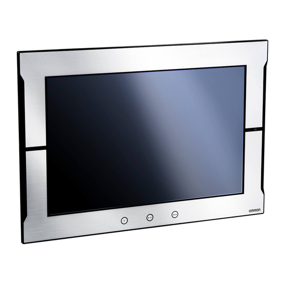
7-2 NA Series Lineup 7-2-1 NA Series Lineup The NA series offers the lineup of 7-inch, 9-inch, 12-inch and 15-inch screen sizes. The model differs depending on the screen size. Models NA5-15W□□□□ NA5-12W□□□□ NA5-9W□□□□ NA5-7W□□□□ Screen Size 15 inches 12 inches... -
Page 64: Revision History
Revision History Revision code Date Revised content September 2015 Original production December 2018 Correction of related manual numbers... - Page 65 Note: Do not use this document to operate the Unit. 2015 V421-E1-02 1218 (0915)
Need help?
Do you have a question about the NA Series and is the answer not in the manual?
Questions and answers